Rice Lake 820i Installation Instructions Manual
Programmable hmi indicator/controller
Hide thumbs
Also See for 820i:
- Installation manual ,
- Technical manual (116 pages) ,
- Operation manual (34 pages)
Advertisement
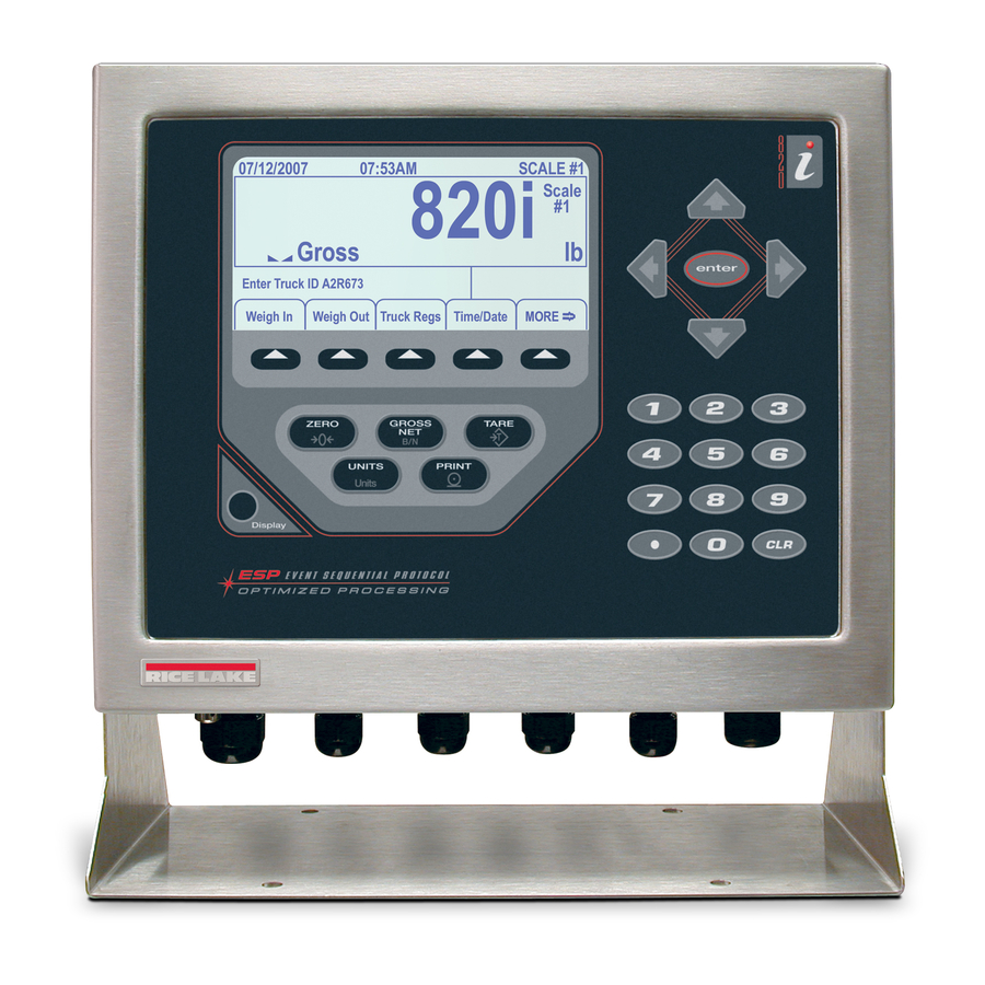
Programmable HMI Indicator/Controller
820i
™
Panel Mount Enclosure Installation Instructions
This document contains drawings, replacement parts lists, and instructions for installing panel mount models of
820i indicators. See the 820i Installation Manual, PN 93018, for general installation and configuration and
calibration information.
The 820i has no on/off switch. Before opening the unit, ensure the power cord is disconnected from the
WARNING
power outlet.
Use a wrist strap for grounding and to protect components from electrostatic discharge (ESD) when
working inside the indicator enclosure.
This unit uses double pole/neutral fusing which could create an electric shock hazard. Procedures
requiring work inside the indicator must be performed by qualified service personnel only.
The supply cord serves as the power disconnect for the 820i. The power outlet supplying the indicator
must be installed near the unit and be easily accessible.
9.16"
8.02"
November 7, 2015
11.56"
10.51"
Figure 1. Panel Cutout for Panel Mount Enclosure
OUTER PERIMETER OF
EXTERIOR FACEPLATE
(SOLID LINE)
PANEL CUTOUT
(DASHED LINE)
INTERIOR HOUSING
(DOTTED LINE)
PN 95304 Rev A
Advertisement
Table of Contents

Related Manuals for Rice Lake 820i


Summary of Contents for Rice Lake 820i
- Page 1 This document contains drawings, replacement parts lists, and instructions for installing panel mount models of 820i indicators. See the 820i Installation Manual, PN 93018, for general installation and configuration and calibration information. The 820i has no on/off switch. Before opening the unit, ensure the power cord is disconnected from the WARNING power outlet.
- Page 2 Secure the bracket to the enclosure using the six 1/4" screws provided in the parts kit (PN 94435), then use the nine 1-1/2" screws (PN 82425) to secure the clinching bracket to the panel door. See Figure 3. Figure 3. Clinching Bracket Assembly 820i Panel Mount Installation...
- Page 3 • Route stripped cables under cabling bar and through the clamps. Ensure shields contact grounding clamps. Tighten grounding clamp nuts. • Use cable ties to secure cables to cabling bar. 820i Panel Mount Installation...
- Page 4 10-position screw terminals for J5 and J11 (2) Table 6. Parts Kit Contents Replacement Parts and Assembly Drawings Table 7 lists replacement parts for the 820i panel mount models, including all parts referenced in Figures 8 and 9. See Figure Number...
- Page 5 Power cord, 230 VAC European units (1) * Additional parts included in parts kit. CAUTION To protect against the risk of fire, replace fuses only with same type and rating fuse. Table 7. Replacement Parts (Continued) Figure 8. Panel Mount Enclosure 820i Panel Mount Installation...
- Page 6 Figure 9. Panel Mount Enclosure, Ground Connections 820i Panel Mount Installation...
Need help?
Do you have a question about the 820i and is the answer not in the manual?
Questions and answers