Rice Lake 720i Installation Manual
Programmable hmi indicator/controller
Hide thumbs
Also See for 720i:
- Installation manual ,
- Technical manual (134 pages) ,
- Installation (4 pages)

Subscribe to Our Youtube Channel
Related Manuals for Rice Lake 720i


Summary of Contents for Rice Lake 720i
- Page 1 Programmable HMI Indicator/Controller Version 2.01 720i Batching Version 1.01 Installation Manual PN 103121 Rev C...
-
Page 3: Table Of Contents
Course descriptions and dates can be viewed at www.ricelake.com/training or obtained by calling 715-234-9171 and asking for the training department. © Rice Lake Weighing Systems. All rights reserved. Printed in the United States of America. Specifications subject to change without notice. - Page 4 11.12 Alibi Tracking ............. . . 110 Rice Lake continually offers web-based video training on a growing selection of product-related topics at no cost.
- Page 5 11.13 Dimension Drawings ............111 11.14 Printed Information.
- Page 6 This page intentionally blank.
-
Page 7: About This Manual
See Section 3.1 on page 18 for information about configuration methods. Authorized distributors and their employees can view or download this manual from the Rice Lake Weighing Systems distributor site at www.ricelake.com The Operator Card included with this manual provides basic operating instructions for users of the . -
Page 8: Introduction
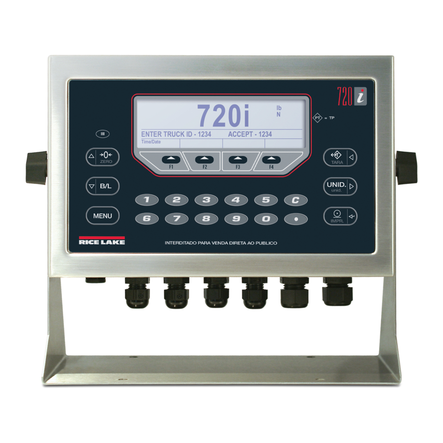
Front Panel utility. universal model front panel, shown in 720i The 720i can be loaded with either PCE software or Figure 1-1, consists of a 22-button keypad with an batching software. Refer to Section 8.0 on page 65 720i L C D d i s p l a y. T h e k e y s a r e g r o u p e d a s f o u r or Section 9.0 on page 81 for further information on... -
Page 9: Operating Modes
1. In gross mode, remove all weight from the Revolution III 720i scale and wait for the standstill annunciator two Windows-based applications that extend its c a p a b i l i t i e s f o r b a t c h c o n t r o l a n d d a t a b a s e management. -
Page 10: Softkey Operations
Press the key twice to clear the accumulator. CLEAR ticket for truck weighing applications. With the panel mount version of the 720i, you ***Truck Regs Displays truck register; allows deletion of need to use CLR Accumulator DigIn Function individual or all entries. Truck register can to clear the indicator. -
Page 11: System Configurations And Options
Version 1.01). 720i EtherNet/IP communications card 87803 DeviceNet interface card 68541 Allen-Bradley Remote I/O interface card 68539 Profibus DP interface card 68540 USB interface card 93245 Fiber-optic interface card 96736 Table 1-3. Part Numbers for 720i Option Cards Introduction... -
Page 12: Installation
The shipping carton should contain the indicator, this NOTE: Install lockwashers manual, and a parts kit. If any parts were damaged in first, against backplate, shipment, notify Rice Lake Weighing Systems and the under grounding clamp shipper immediately. Cut insulation here for braided cables See Section 2.9 on page 11 for parts kit contents. -
Page 13: Load Cells
For load cell cables, cut the shield wire just past the grounding clamp. Shield wire function Communications ports on the CPU board support 720i is provided by contact between the cable shield PS/2-type remote keyboard, full duplex RS-232, and and the grounding clamp. -
Page 14: Digital I/O
INPUT PCEE (DIG I/O menu) and using to monitor the bit. However, the fastest pulse rate that can be counted using a digital input is 10Hz (10 pulses per second). 720i Installation Manual... - Page 15 JUMPERS LOAD CELL CONNECTOR SERIAL PORT 1 SERIAL PORT 3 SERIAL PORT 4 DIGITAL I/O SERIAL PORT 2 PS/2 DISPLAY Figure 2-3. 720i CPU Board COM 1 COM 0 Programming Port CPU Interface Port Figure 2-4. 720i Display Board Installation...
-
Page 16: Slot Assignments
Analog output card Analog 2 Bus communications cards Bus Option 2 Table 2-5. 720i Slot Assignments Enclosure Reassembly CPU Board Removal Once cabling is complete, position the backplate over If you must remove the CPU board, use the 720i the enclosure and reinstall the backplate screws. -
Page 17: Battery Replacement
2.2 VDC. Life expectancy of the battery is ten years. Replacement Parts and Assembly Drawings 2.9.1 Universal Model Table 2-6 lists replacement parts and parts kit contents for the universal enclosure model, including all parts 720i referenced in Figures 2-6 through 2-8. Ref Number Description (Quantity) See Figure... - Page 18 71344 10-position screw terminal for J6 (1) 76513 4-position screw terminals for J3 and J5 (2) 76514 6-position screw terminals for J1, J2 and J4 (3) 94422 Capacity label (1) Table 2-6. Universal Model Replacement Parts (Continued) 720i Installation Manual...
- Page 19 Figure 2-6. 720i Universal Model Assembly, Enclosure and Tilt Stand Installation...
- Page 20 From Power Supply Figure 2-7. 720i Universal Model, CPU Board and Backplate Ground wire (13) to backplate (22) Grounding Stack Ground wire from power cord (15) Figure 2-8. 720i Universal Model, Grounding Detail 720i Installation Manual...
-
Page 21: Panel Mount Controller
2.9.2 Panel Mount Controller Table 2-7 lists replacement parts and parts kit contents for the panel mount controller, including all parts 720i referenced in Figure 2-9 on page 16. Ref Number Description (Quantity) 103314 Panel mount controller cover (1) 103677... - Page 22 Figure 2-9. Panel Mount Controller Assembly 720i Installation Manual...
-
Page 23: Panel Mount Display
94422 Capacity label (1) 53075 Cable shield ground clamp (1) 71522 Machine screws, 8-32NC x 1/4 (4) 82425 Machine screws, 10-32NF x 1.50 (7) Table 2-8. Panel Mount Display Unit Replacement Parts Figure 2-10. 720i Panel Mount Display Assembly Installation... -
Page 24: Configuration
Revolution III Figure 3-2. Revolution III Display for 720i PCE Version data is downloaded to the indicator. s u p p o r t s b o t h u p l o a d i n g a n d... -
Page 25: Serial Command Configuration
The serial command set can be used to configure the partial weighing ranges, each with different scale indicator using either a personal computer, display divisions. The scale interval changes with both 720i terminal, or remote keyboard. Like increasing and decreasing loads applied. Revolution III... -
Page 26: Menu Structures And Parameter Descriptions
Display installed software version number. The RSConfig softkey on the Version menu can be used to restore all configuration parameters to their default values. Table 3-1. 720i Menu Summary The following sections provide graphic representations of the menu structures and tables describing the menu 720i parameters. - Page 27 Level Level Parameter Parameter Level Level Parameter Parameter Default value Value Value Value When moving through values below the first menu level, press to return to the level above. Press to move to the next parameter on the level above. Figure 3-6.
-
Page 28: Scales Menu
32OUT 64OUT 128OUT 100D 200D 250D RATTRAP SMPRAT PWRUPMD TAREFN ACCUM VISIBL PEAK HOLD 30HZ BOTH 120HZ DELAY NOTARE NORMAL 240HZ PBTARE BI-DIR 480HZ KEYED AUTO 960HZ 7.5HZ 15HZ 60HZ CALIBR CALIBR Submenu Figure 3-7. SCALES Menu 720i Installation Manual... - Page 29 SCALES Menu Parameter Choices Description Level 2 submenus SCALE 1 Allows configuration and calibration of each scale CONFIG Scale hardware configuration (A/D or serial scale) Level 3 submenus GRADS 10000 Specifies the number of full scale graduations if SPLIT=OFF. (For multi-range and ...
- Page 30 KEYED: Keyed tare enabled ACCUM Accumulator. Specifies whether the scale accumulator is enabled. If enabled, accumulation occurs whenever a print operation is performed. VISIBL Scale visibility. Specifies whether scale data is displayed. Table 3-2. SCALES Menu Parameters (Continued) 720i Installation Manual...
- Page 31 SCALES Menu Parameter Choices Description PEAK HOLD Peak hold. Used to determine, display, and print the greatest net weight read during a NORMAL weighing cycle. The weighing cycle ends when a print command is executed (AUTO setting) BI-DIR or when the peak weight is cleared by pressing ZERO or PRINT. Press GROSS/NET to AUTO display gross weight data when using the peak hold function.
- Page 32 8888888 number 8888880 8888880 8888800 8888800 8.888888 8.888888 88.88888 88.88888 888.8888 888.8888 troyoz 8888.888 troylb 8888.888 88888.88 88888.88 888888.8 CUSTOM NONE UNITS INTERVL REFRESH 0.100000 number number HOUR Figure 3-8. SCALES Menu, FORMAT Submenu, SPLIT = OFF 720i Installation Manual...
- Page 33 SCALES Menu, FORMAT Submenu, SPLIT = OFF Parameter Choices Description Level 4, FORMAT submenu PRIMAR DECPNT Specifies the decimal position, display divisions, and units used for the primary units. See DSPDIV Level 5 submenu parameter descriptions. UNITS SECNDR DECPNT Specifies the decimal position, display divisions, units, and conversion multiplier used for the DSPDIV secondary units.
- Page 34 20 * 0.1 = 2 Note that setting both PRIMARY and ROC display resolutions to 1 LB would have resulted in a step size of 20 LB. Table 3-3. SCALES Menu, FORMAT Submenu Parameters, SPLIT = OFF (Continued) 720i Installation Manual...
- Page 35 SCALES Menu, FORMAT Submenu, SPLIT = OFF Parameter Choices Description DECPNT 8888888 Decimal point location. Determines the location of the decimal point or dummy zeros in the 8888880 display. 8888800 8.888888 88.88888 888.8888 8888.888 88888.88 888888.8 DSPDIV Display divisions. Selects the minimum division size for the ROC units displayed weight. MULT Multiplier.
- Page 36 88888.88 MAX3 UNITS DECPT3 DDIV3 10000 888888.8 weight 8888888 8888880 8888800 8.888888 88.88888 888.8888 troyoz 8888.888 If SPLIT = 3RNG or 3INTVL troylb 88888.88 CUSTOM NONE Figure 3-9. FORMAT Submenu, SPLIT OFF (Multi-range and Multi-interval Scales) 720i Installation Manual...
- Page 37 SCALES Menu, FORMAT Submenu, SPLIT Parameter Choices Description Level 4, FORMAT submenu DECPT1 8888888 Decimal point location for first range or interval. Specifies the location of the decimal point or 8888880 dummy zeroes in the primary unit display. Value should be consistent with local legal 8888800 requirements.
- Page 38 Press ENTER to remove an offset value from the zero and span calibrations. Use this parameter only after WZERO and WSPAN have been set. See Section 4.2 on page 47 for more information about using this parameter. Table 3-5. SCALES Menu, CALIBR Submenu Parameters 720i Installation Manual...
-
Page 39: Serial Menu
28800 7ODD 38400 8ODD 57600 8EVEN 115200 1200 2400 4800 HANDSHK STREAM SOURCE SFMT format List of configured XONXOFF 720i Batching Version only scales HRDWAR INDUST If STREAM ≠ OFF 4KEYS KEYPAD DISPLAY Figure 3-11. SERIAL Menu, Port 2 Configuration... - Page 40 2400 for PORT 7 FULL number 4800 (serial expansion card) only If PORTTYPE = 485 STREAM TOKENS SFMT 720i Batching Version only format PRIMAR TARE If PORT = CMD INDUST 720i Batching Version only Selectable token characters 4KEYS KEYPAD If STREAM = LFT or INDUST...
- Page 41 Industrial (non-legal-for-trade) scale input KEYBD is available only on Port 1; SCALE, IND SC are available only on Port 4 and higher (expansion ports). 720i The keyboard interface is not hot-pluggable. Power-off the before attaching keyboard cable to the Port 1 connector.
- Page 42 Specifies the stream format used for the streamed data (CMD scale type). The default format is the Rice Lake format (see Section 11.6 on page 106). See Section 11.5 on page 103 for information about custom stream formatting. Table 3-6. Serial Menu Parameters (Continued)
-
Page 43: Feature Menu
See Table 3-7 on page 38 for parameter descriptions. SCALES SERIAL FEATURE PFORMT SETPTS DIG I/O ALGOUT VERS 720i Batching Version only see page 57 DECFMT CONSNUM CONSTUP DATE TIME DATEFMT DATESEP... - Page 44 Specifies whether data storage is used by the alibi feature to allow reprinting any transaction. Use the SOFTKEYS parameter to enable a softkey for recalling alibi print transactions. See Section 11.12 on page 110 for more information about using the alibi feature. Table 3-7. FEATURE Menu Parameters 720i Installation Manual...
- Page 45 Display Tare Display Accum Display ROC Alibi Setpoint These features are only available with the 720i Batching version software. Batch Start Batch Stop Batch Pause Batch Reset Weigh These features are available with the Advanced Truck Mode Only.
- Page 46 Specifies the shift start and end time in 24 hour format (HHMMSS) SHIFT # END DAY START HHMMSS Specifies the day start and end time in 24 hour format (HHMMSS) DAY END HHMMSS Table 3-7. FEATURE Menu Parameters (Continued) 720i Installation Manual...
- Page 47 See Section 11.2 on page 101 for more information about regulatory mode functions. SCALES SERIAL FEATURE PFORMT SETPTS DIG I/O ALGOUT VERS 720i Batching Version only REGULAT see page 57 INDUST SNPSHOT HTARE ZTARE KTARE MTARE...
-
Page 48: Pformt Menu
Batching Version Software Only GFMT NFMT ACCFMT SPFMT TRWIN TRWOUT TRFMT ALERT See GFMT Menu HDRFMT1 HDRFMT2 AUXFMT PORT AUX1FMT AUX20FMT PORT 4 PORT Same as AUXFMT1 PORT 2 PORT 4 PORT 2 Figure 3-15. PFORMT Menu 720i Installation Manual... -
Page 49: Dig I/O Menu
I/O bits available on the CPU board (connector J6). The additional slot, with 24 I/O bits, is shown only if the digital I/O expansion card is installed. SCALES SERIAL FEATURE PFORMT SETPTS DIG I/O ALGOUT VERS 720i Batching Version only see page 57 … SLOT 0 SLOT 2 … … BIT 1 BIT 2... - Page 50 PRIM • CLRTAR clears the current tare for the active scale. • CLRACC clears the active accumulator. CLRTAR CLRACC * 720i Batching Software Version Only Table 3-9. DIG I/O Menu Parameters 720i Installation Manual...
-
Page 51: Algout Menu
See the Analog Output Card Installation Instructions, PN 69089, for more information. SCALES SERIAL FEATURE PFORMT SETPTS DIG I/O ALGOUT VERS 720i Batching Version only see page 57 ALGOUT2 SOURCE1 MODE OFFSET ERRACT MINNEG MAXNEG... -
Page 52: Fldbus Menu
There are no parameters associated with the Version menu: when selected, the indicator displays the installed software version number. SCALES SERIAL FEATURE PFORMT SETPTS DIG I/O ALGOUT VERS 720i Batching Version only Software see page 57 version Figure 3-19. Version Menu 720i Installation Manual... -
Page 53: Calibration
Calibration ® can be calibrated using the front panel, serial commands, or . Each method consists of the 720i Revolution III following steps: • Zero calibration • Entering the test weight value • Span calibration • Optional five-point linearization •... -
Page 54: Serial Command Calibration
The SC.WLIN#1.C1 command calibrates the Repeat for up to five linearization points. To point. Repeat using the SC.WLIN#1.Vx and exit the linearization parameters, press the SC.WLIN#1.Cx commands as required for key to return to WLIN. additional linearization points. 720i Installation Manual... -
Page 55: Revolution Calibration
Calibration Wizard provides Revolution III step-by-step scale calibration. With the connected 720i to the PC, select the scale and click on the scale icon in the Calibration Wizard from the Tools menu on the Scales display, then follow the steps Revolution III listed below to calibrate the scale. -
Page 56: Using Revolution
Revolution III attempts to establish communications to the indicator. If communications settings need to be adjusted, select The 720i uses two different version software depending upon the application. They are: from the Tools menu. Options… • 720i Batching version software Downloading to the Indicator •... -
Page 57: Installing Software Upgrades
720i available. To download a new software version, select and the Rice Lake Web Update application. To use the the new software version and click on Get Selection Web Update application, install the program from the Once the new software is downloaded to the PC, do the Tool Kit CD. -
Page 58: Print Formatting
Number of accumulations, scale n <AT> Time of last accumulation, current scale <AT#n> Time of last accumulation, scale n <AD> Date of last accumulation, current scale <AD#n> Date of last accumulation, scale n Truck Mode Commands Table 6-1. Print Format Commands 720i Installation Manual... - Page 59 Command Description Supported Ticket Formats <TID> Truck ID number TRWIN, TRWOUT <TR1> Gross weight for current ticket in displayed units <TR2> Tare weight for current ticket in displayed units <TR3> Net weight for current ticket in displayed units TR1, TR2, and TR3 truck ticket weight data includes keywords INBOUND, KEYED, RECALLED, as necessary. See Table 7-3 on page 60 for Advance Truck commands Setpoint Commands <SCV>...
-
Page 60: Default Print Formats
See Table 7-5, “Default Print Formats for Advanced Truck,” on page 61 In OIML and CANADA modes, the letters PT (preset tare) are automatically inserted after the printed tare weight. * 720i Batching Version only Table 6-2. Default Print Formats 720i Installation Manual... -
Page 61: Customizing Print Formats
Customizing Print Formats The following sections describe procedures for customizing print formats using the configuration Revolution III utility or serial commands. See Section 11.5 on page 103 for information about custom stream formatting. 6.3.1 Using Revolution configuration utility provides a ticket formatting grid with a tool bar. The grid allows you to Revolution III construct the ticket format without using the formatting commands (<NL>... -
Page 62: Using The Front Panel
• To delete a character, position the cursor to the right of the character to be deleted from the format string, then press the key. 720i Installation Manual... -
Page 63: Using Serial Commands
With a personal computer, terminal, or remote keyboard attached to one of the serial ports, you can use the 720i serial command set described in Table 6-1 on page 52 to customize the print format strings. To view the current setting of a format string, type the name of the print format and press the key. -
Page 64: Truck Modes
Weigh In Weigh Out Truck Regs let you keep a database of truck IDs and Figure 7-1. 720i Display, showing Truck Modes 1-6 Softkeys Stored IDs weigh-in weights in the indicator’s memory. The Using the Truck Regs Display indicator can automatically store up to 1000 truck IDs and tares;... -
Page 65: Weigh-In Procedure
Weigh-In Procedure Single-Transaction Tare Weights and IDs In modes 1 and 2, the indicator erases truck ID numbers and tare weights from memory after the One-time transactions are supported in all modes that transaction. In modes 3–6, the truck ID and weigh-in can be configured to use stored IDs (modes 3–6). - Page 66 Weigh Reports Management To change the format serially send: Figure 7-3. 720i Display, showing Advance Mode Softkeys AUXFMT.FMT#n=<><><><CR> Start the Weigh-In and Weigh-Out Weigh P r o c e d u r e . S e e “ A d v a n c e M o d e...
- Page 67 Command Description <RTT> Report Total Tare <RTN> Report Total Net <RSD> Report Start Date (used for summary reports) <RED> Report End Date (used for summary reports) <SBG> Subtotal Gross <SBN> Subtotal Net <SBT> Subtotal Tare Table 7-4. Print Format Commands Continued Advance Mode Default Print Formats Table 7-5 shows the default print formats for ADVANCE mode.
- Page 68 Weigh Enter 3. Indicator generates the weigh-out ticket. The truck may be empty or loaded for either of the above procedures. The 720i will calculate the proper net weight. Advance Mode Keyed Tare If the truck tare weight is known, Advance Mode keyed tare allows for both weigh-in and weigh-out to be performed in one transaction.
-
Page 69: Advance Mode Menus
7.6.1 Advance Mode Menus Advance Mode Reports Menu In Advance Mode the softkeys are enabled. The softkey is described Weigh Reports Management Reports below. While in a submenu the TARE key can be pressed to go back to the previous menu. If using the PS2 keyboard, the ESC key will take you to the previous menu. - Page 70 Specifies which transactions to delete. The system offers a Yes or No to confirm INCOMPLETE prompt before the transactions are deleted. The system can store 1496 transactions. COMPLETE You must manually delete the transactions when the system is full. Table 7-7. Management Menu Parameters 720i Installation Manual...
-
Page 71: Setpoints
Batch setpoints Directions in this chapter require the batching ordered sequence. The can use setpoints to version of software (720i batching). 720i control up to 32 separate batch processing steps. indicator provides 32 configurable setpoints A digital output associated with a batch setpoint is... - Page 72 The digital output associated with this setpoint becomes active when the START setpoint becomes the current batch step and remains active until the timer expires. Table 8-1. Setpoint Kinds (Continued) 720i Installation Manual...
- Page 73 Kind Description Batch Continuous Time of day setpoint. Performs functions when the internal clock time of the indicator matches the specified setpoint time. DELTA Delta weight setpoint. Satisfied when the change in weight on the scale is equal to or exceeds the absolute value specified for the setpoint. CHKWEI Checkweigher setpoint.
-
Page 74: Setpoint Menu Parameters
RESREL PAUSE DELAY WAITSS COUNTER AUTOJOG Go to B Go to C INMOTON INRANGE BATCHPR TIMER CONCUR Go to E Go to D NEVER DELTA CHKWEI ALWAYS Go to F Go to G Figure 8-1. SETPTS Menu 720i Installation Manual... - Page 75 GROSS –GROSS ACCUM –NET Same as GROSS VALUE SOURCE TRI P BANDVAL HYSTER number number number HIGHER Scale 1 LOWER If TRIP=INBAND If TRIP=HIGHER INBAND GROSS, NET, –GROSS, and OUTBAND TRIP=OUTBAND TRIP=LOWER –NET setpoints only PREACT PREVAL PREADJ PRESTAB PCOUNT TOLBAND TOLCNT number...
- Page 76 WAITSS SLOT DIGOUT SENSE BRANCH List of available NONE NORMAL output bits for INVERT 1–32 specified slot List of available digital I/O slots If SLOT≠NONE If BA TCH=ON Figure 8-3. +REL, –REL, %RELS and RESREL Setpoint Parameters 720i Installation Manual...
- Page 77 P AUSE and COUNTER setpoints VALUE ACCESS NAME SENSE BRANCH SLOT DIGOUT List of available number NONE NONE NORMAL output bits for specified slot HIDE 1–30 1–32 INVERT List of available digital I/O slots COUNTER COUNTER If SLOT≠ NONE setpoints only setpoints only DELAY, WAITSS, and AUTOJOG setpoints VALUE...
- Page 78 SLOT DIGOUT number 1–32 1–32 List of available NORMAL NONE NONE output bits for INVERT HIDE 1–30 specified slot List of available digital I/O slots If SLOT≠ NONE Figure 8-5. COZ, INMOTON, INRANGE, and BATCHPR Setpoint Parameters 720i Installation Manual...
- Page 79 TOD setpoints TIME DURATION SOURCE time entry time entry Scale 1 TOD setpoints only BATCH CLRACCM CLRTARE PSHACCM PSHPRNT PSHTARE ONQUIET WAITSS ACCESS NAME SLOT DIGOUT SENSE List of available NONE NONE NORMAL output bits for HIDE 1–30 INVERT specified slot List of available digital I/O slots If SLOT≠...
- Page 80 List of available List of available NONE output bits for output bits for output bits for specified slot specified slot specified slot List of available digital I/O slots If SLOT≠ NONE Figure 8-7. DELTA and CHKWEI Setpoint Parameters 720i Installation Manual...
- Page 81 ALWAYS NEVER BRANCH 1–32 Figure 8-8. ALWAYS and NEVER Setpoint Parameters SETPTS Menu Parameter Choices Description Level 2 submenus SETPT 1– Specifies the setpoint kind. SETPT 32 GROSS GROSS, NET, –GROSS, –NET, ACCUM, ROC, +REL, –REL, %REL, RESREL. and TOD setpoint kinds can be used as either batch or continuous setpoints. –GROSS –NET PAUSE, DELAY, WAITSS, COUNTER, AUTOJOG, DELTA, ALWAYS, and NEVER...
- Page 82 If the captured weight is not within the specified tolerance band, the preact learn function is not applied and the batch is paused (based on the value of the TOLCNT parameter, below) until restarted or reset. Table 8-2. Setpoint Menu Parameters (Continued) 720i Installation Manual...
- Page 83 SETPTS Menu Parameter Choices Description TOLCNT Tolerance count. For setpoints with TRIP set to HIGHER or LOWER, specifies the 0–65535 number of consecutive batch cycles in which the tolerance band (TOLBAND parameter) must be exceeded before the batch process is paused. When the specified value is met, the batch is paused and an error message is displayed.
- Page 84 VOVER value specified. SENSE NORMAL Specifies whether the value of the digital output associated with this setpoint is INVERT inverted when the setpoint is satisfied. Table 8-2. Setpoint Menu Parameters (Continued) 720i Installation Manual...
-
Page 85: Batch Operations
Softkeys can be configured to allow operator control of setup mode. Use the DIG I/O menu (see Section 3.2.5 batch operations from the front panel (see 720i on page 43) to configure digital input and output Figure 8-9), Softkeys can be configured using functions. - Page 86 1. Turn 3-way switch to ABORT 2. Unlock STOP button (OUT position) 3. Turn 3-way switch to START Use this procedure (or the BATRESET serial command) to initialize the new batch routine following change setpoint configuration. 720i Installation Manual...
-
Page 87: Using Proaction Pcee
, the is supported by two additional applications that extend its capabilities for Revolution III 720i batch control and database management. ProAction PCEE, or Process Control Engine Editor, provides functions similar to setpoint configuration for -based batch control. ProAction DBE, the database editor, is a tool for... - Page 88 Use of the database is addressed using the database commands discussed later in this document. Revolution Whenever a PCE process is built, be sure to build a hardware configuration file using the 720i Revolution III module so that all configuration parameters match the process. The...
- Page 89 To create this process: 1. Install both the PCEE program and the DBE program. 2. Open the PCEE program. 3. Click button. New Step The Step dialog box appears. 4. In the Step Name text box, type the desired name for this step. 5.
- Page 90 For ease in debugging your process, there is an EDP command that will dump the raw list of commands you have sent to the 720i, "SPSUMP." The first half of the list is all the conditions and actions. The second half lists the steps and associated conditions and actions by numeric reference.
- Page 91 Eight databases are allowed, but as the number increases the size of each is reduced. Slot is usually 0 as memory card expansion options are not allowed in the 720i. There are two actions that are similar but need further definition. They are the .
-
Page 92: Serial Commands
Table 10-1. Serial Key Press Commands (Continued) KUNITS In weighing mode, press the UNITS key KPRIM Go to primary units (pseudo key) KSEC Go to secondary units (pseudo key) KTER Go to tertiary units (pseudo key) Table 10-1. Serial Key Press Commands 720i Installation Manual... -
Page 93: Reporting Commands
Most parameter values can be changed in setup mode only. SPDUMP Print configuration PCEE Use the following command syntax when changing VERSION Write software version 720i parameter values: , where command=value<ENTER> value HARDWARE Lists installed option cards. is either a number or a parameter value. Use no spaces Section 11.1.2 on page 99 for more... - Page 94 SC.PEAKHOLD#1 Peak hold OFF, NORMAL, BI-DIR, AUTO SC.WZERO#1 Zero calibration — SC.WVAL#1 Test weight value test_weight_value SC.WSPAN#1 Span calibration — SC.WLIN.F1#1– Actual raw count value for linearization 0–16777215 SC.WLIN.F5#1 points 1–5 Table 10-3. SCALES Serial Commands (Continued) 720i Installation Manual...
- Page 95 Command Description Values SC.WLIN.V1#1– Test weight value for linearization points 0.000001–9999999 SC.WLIN.V5#1 1–5 SC.WLIN.C1#1– Calibrate linearization points 1–5 — SC.WLIN.C5#1 SC.LC.CD#1 Deadload coefficient — SC.LC.CW#1 Span coefficient — SC.LC.CZ#1 Temporary zero — SC.REZERO#1 Rezero — Table 10-3. SCALES Serial Commands (Continued) Command Description Values...
- Page 96 Display or Scale weight source DISPLAY, SCALE REG.HTARE Allow tare in display hold NO, YES REG.ZTARE Remove tare on ZERO NO, YES * 720i Batch Version Software only REG.KTARE Always allow keyed tare NO, YES REG.MTARE Multiple tare action REPLACE, REMOVE, NOTHING REG.NTARE...
- Page 97 TARE, UNITS, PRINT, ACCUM, SETPNT, TIMDATE, ESC, CLEAR, DSPTAR, KEY0–KEY9, KEYDP, ENTER, NAVUP, NAVDN, NAVLFT, NAVRGT, KBDLOC, HOLD, BATRUN*, BATSTRT*, BATPAUS*, BATRESET*, BATSTOP*, CLRCN, GROSS, NET, PRIM, SEC, CLRTAR, CLRACC, * 720i Batch Version Software only Table 10-7. DIG I/O Serial Commands Serial Commands...
- Page 98 Push print OFF, ON, WAITSS SP.PSHTARE#n Push tare OFF, ON SP.ALARM#n Alarm enable OFF, ON SP.NAME#n Setpoint name number NONE, 1–30 SP.ACCESS#n Setpoint access OFF, ON, HIDE SP.DSLOT#n Digital output slot NONE, SLOTx SP.DIGOUT#n Digital output BITx 720i Installation Manual...
-
Page 99: Normal Mode Commands
Command Description Values SP.SENSE#n Digital output sense NORMAL, INVERT SP.BRANCH#n Branch destination 0, 1-32 SP.RELNUM#n Relative setpoint number 1–32 SP.START#n Starting setpoint 1–32 SP.END#n Ending setpoint 1–32 SP.DISLOT#n Digital input slot NONE, SLOTx SP.MASK#n Digital input mask number SP.NSAMPLE#n Number of samples number SP.TIME#n Trip time... -
Page 100: Batching Control Commands
Table 10-10. Normal Mode Serial Commands 10.1.6 Batching Control Commands The commands listed in Table 10-11 provide batching control through the serial port The following batch control commands only apply to the 720i Batch Version Software only. Command Description Values... -
Page 101: Database Commands
(0 is the onboard memory) create and maintain databases in the . Except for 720i t he command, all of the database D B . D E L A L L represents a single cell of a row of data... - Page 102 <Data Type> Value Type Byte Short (16-bit integer) Long (32-bit integer) Single (32-bit floating point) Double (64-bit floating point) Fixed string Variable string Date and time Table 10-14. Data Type Field Codes 720i Installation Manual...
-
Page 103: Advance Mode Edp Commands
0 - 9999999 Table 10-16. Advance Mode EDP Commands The 720i must see six digits of data for the time values in the first 8 parameters. If the 720i does not see at least 000000 it will respond with ??. -
Page 104: Appendix
Required option card not found. See Section 11.1.1 on page 99. Table 11-1. Basic Troubleshooting ® Revolution III Always save copies of the indicator configuration, calibration, files on a local PC so that these are available when a software reload or upgrade is required. 720i Installation Manual... -
Page 105: Option Card Diagnostic Errors
If command returns a code of for that slot), ensure that 720i the current indicator configuration requires an option the card is seated properly. Reinstall the card, if card but that card is not detected at power-up, an error... -
Page 106: Using The Xe Serial Command
16384 Gravity calibration error ADPHYSICALERR 32768 A/D physical error TAREERR 65536 Tare checksum error STRINGERR 262144 String program error POWER_FAIL 524288 Power failure RTCERR 1048576 Real time clock error Table 11-4. Error Codes Returned on XE Command 720i Installation Manual... -
Page 107: Regulatory Mode Functions
11.2 Regulatory Mode Functions The function of the front panel keys depends on the value specified for the REGULAT parameter TARE ZERO on the FEATURE menu. Table 11-5 describes the function of these keys for the NTEP, CANADA, OIML, and NONE regulatory modes. -
Page 108: Serial Scale Interface
<W7.2> 3. Use to edit the SFMT parameter rather than <W7.>. Revolution III to match the format sent by the serial scale. See Section 11.5 for more information about stream formatting and format identifiers. 720i Installation Manual... -
Page 109: Local/Remote Operation
11.4 Local/Remote Operation For truck scale and similar applications, local/remote support provides function equivalent to that of a legal-for-trade remote display with keypad. Scale data from the local indicator is also displayed at the remote unit, and keypad input from the remote allows transactions to be initiated from either the local or remote unit. To configure for local/remote operation, first set up the local unit (including truck mode and database information, as required) as an A/D scale. - Page 110 =000 if current DECPNT=8888800 =001 if current DECPNT=8888880 =010 if current DECPNT=8888888 =011 if current DECPNT=888888.8 =100 if current DECPNT=88888.88 =101 if current DECPNT=8888.888 =110 if current DECPNT=888.8888 =111 if current DECPNT=88.88888 Table 11-8. Custom Stream Format Identifiers 720i Installation Manual...
- Page 111 Format Identifier Defined By Description Configuration =000 if primary DECPNT=8888800 =001 if primary DECPNT=8888880 =010 if primary DECPNT=8888888 =011 if primary DECPNT=888888.8 =100 if primary DECPNT=88888.88 =101 if primary DECPNT=8888.888 =110 if primary DECPNT=888.8888 =111 if primary DECPNT=88.88888 Configuration =000 if secondary DECPNT=8888800 =001 if secondary DECPNT=8888880 =010 if secondary DECPNT=8888888 =011 if secondary DECPNT=888888.8...
-
Page 112: Data Formats
EDP serial command decimal ASCII 13 decimal Address of the r eceiving indicator NOTE: Host must send <CR>, not <CR><LF>. Failure to use <CR> renders all indicators unable to respond to serial commands Figure 11-2. RS-485 Send Data Format 720i Installation Manual... -
Page 113: Digital Filtering
11.7 Digital Filtering suspended. Set DFTHRH to NONE to turn off the filter override. Standard digital filtering uses mathematical averaging to eliminate the variant digital readings that the A/D Setting the Digital Filter Parameters converter sends periodically because of external Fine-tuning the digital filter parameters greatly vibration. -
Page 114: Conversion Factors For Secondary Units
1.215278 troy pounds 0.907185 metric tons 0.000500 short tons metric tons 2204.62 pounds 0.000446 long tons 1000.00 kilograms 0.000453 metric tons 1.10231 short tons 0.984207 long tons Table 11-9. Conversion Factors Table 11-9. Conversion Factors (Continued) 720i Installation Manual... -
Page 115: Ps/2 Keyboard Interface
The keyboard interface is not hot-pluggable. Secondary/ 720i Disconnect power before Primary Unit Tertiary Unit x Multiplier connecting the keyboard cable to the Port 1 connector. long tons 2240.00 pounds Function 1016.05 kilograms 1.12000 short tons Softkey 1 1.01605 metric tons... -
Page 116: Display Module Configuration
Table 3-7 on page 38 for description. An alibi softkey also needs to be enabled to provide operator access to the alibi records. This softkey is enabled in the FEATURE menu or through in the base Revolution III configuration menu, under the softkey tab. 720i Installation Manual... - Page 117 11.13 Dimension Drawings 12.24 3.52 10.50 7.25 10.38 10.80 5.25 Figure 11-5. Universal Model Dimensions 6.05 11.00 12.75 2.14 2.05 11.85 Figure 11-6. Panel Mount Controller Dimensions Appendix...
- Page 118 11.14 Printed Information System Manuals • Installation Manual, PN 103121 720i 820i/920i Option Cards (720i/ • Analog Output Card Installation Instructions, PN 69089 • 24-Channel Digital I/O Expansion Card Installation Instructions, PN 69087 • Dual Channel Serial Card Instructions, PN 69090 Communications Options (520/720i/820i/920i) ™...
- Page 119 11.15 Specifications Power Operator Interface AC Power Range 100–240 VAC Display Universal viewable area: 5.3 in x 1.5 in (133 x 39 Frequency 50 or 60 Hz Power Consumption 25 watts maximum Panel mount viewable area: 3.8 in x 1.2 in (96 x 30 mm) 240 x 64 pixel VGA LCD display module with A/D Specifications...
- Page 120 720i Installation Manual...
- Page 123 Specifications subject to change without notice. Rice Lake Weighing Systems is an ISO 9001 registered company. 230 W. Coleman St. • Rice Lake, WI 54868 • USA U.S. 800-472-6703 • Canada/Mexico 800-321-6703 • International 715-234-9171 • Europe +31 (0)26 472 1319 www.ricelake.com www.ricelake.mx www.ricelake.eu www.ricelake.co.in m.ricelake.com...
Need help?
Do you have a question about the 720i and is the answer not in the manual?
Questions and answers