Fluke 787 User Manual
Processmeter
Hide thumbs
Also See for 787:
- User manual (50 pages) ,
- Calibration manual (40 pages) ,
- Safety information (4 pages)
Table of Contents
Advertisement
Advertisement
Table of Contents

Related Manuals for Fluke 787


Summary of Contents for Fluke 787
- Page 1 ProcessMeter™ Users Manual April 1997 Rev. 4, 3/13 © 1997-2013 Fluke Corporation. All rights reserved. Specifications are subject to change without notice. All product names are trademarks of their respective companies. Fluke-Direct .com info@Fluke-Direct.com 1.888.475.5235...
- Page 2 LIMITED WARRANTY AND LIMITATION OF LIABILITY This Fluke product will be free from defects in material and workmanship for three years from the date of purchase. This war- ranty does not cover fuses, disposable batteries, or damage from accident, neglect, misuse, alteration, contamination, or abnormal conditions of operation or handling.
-
Page 3: Table Of Contents
Table of Contents Title Page Introduction ........................1 Contacting Fluke ......................1 Safety Information ......................2 How to Get Started ......................6 Getting Acquainted with the Meter ................. 7 Measuring Electrical Parameters ..................18 Input Impedance ......................18 Ranges ........................18 Measuring a Composite Signal .................. - Page 4 Maintenance ........................30 General Maintenance ....................30 Calibration ......................... 30 Replacing the Battery ....................30 Replacing a Fuse ...................... 32 If the Meter does not Work ..................33 Replacement Parts and Accessories ................34 Specifications ......................... 37 Fluke-Direct .com info@Fluke-Direct.com 1.888.475.5235...
- Page 5 Range Requirements for Measuring a Composite Signal ............18 Steady mA Output Adjustment ....................25 Steady mA Output Adjustment ....................26 mA Step Values ........................27 Power-Up Options ......................... 28 Typical Alkaline Battery Life ....................29 Replacement Parts ........................ 35 Fluke-Direct .com info@Fluke-Direct.com 1.888.475.5235...
- Page 6 Users Manual Fluke-Direct .com info@Fluke-Direct.com 1.888.475.5235...
- Page 7 List of Figures Figure Title Page Fluke 787 ProcessMeter ......................6 Input/Output Jacks......................... 7 Rotary Switch Positions for Measurements ................9 Rotary Switch Positions for mA Output .................. 11 Pushbuttons .......................... 13 Elements of the Display ......................15 Sourcing Current ........................22 Simulating a Transmitter ......................
- Page 8 Users Manual Fluke-Direct .com info@Fluke-Direct.com 1.888.475.5235...
-
Page 9: Introduction
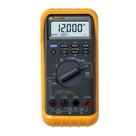
Introduction Contacting Fluke To contact Fluke, call one of the following telephone Warning numbers: Read “Safety Information” before you use the • Technical Support USA: 1-800-44-FLUKE Meter. (1-800-443-5853) Your Fluke 787 ProcessMeter (referred to as “the • Calibration/Repair USA: 1-888-99-FLUKE Product or Meter”) is a handheld, battery-operated tool for... -
Page 10: Safety Information
• Anywhere in the world: +1-425-446-5500 case. Look for cracks or missing plastic. Pay particular attention to the insulation Or, visit Fluke's website at www.fluke.com. surrounding the connectors. To register your product, visit http://register.fluke.com. • Make sure the battery door is closed and latched before operating the Meter. - Page 11 To avoid personal injury or damage to the Meter, use only the specified replacement • For current measurements, connect the fuse, 440 mA 1000 V fast-blow, Fluke PN Meter to the circuit after you remove 943121. circuit power. Always put the Meter in •...
- Page 12 Use the proper jacks, function, and range live test lead. When you disconnect test leads, for your measurement or sourcing disconnect the live test lead first. application. • For best mechanical performance, the Product must remain in the holster at all times. Fluke-Direct .com info@Fluke-Direct.com 1.888.475.5235...
-
Page 13: Symbols
Category: With reference to the equipment types in the WEEE Directive Annex I, this product is classed as category 9 "Monitoring and Control Instrumentation" product. Do not dispose of this product as unsorted municipal waste. Go to Fluke’s website for recycling information. Fluke-Direct .com... -
Page 14: How To Get Started
Users Manual How to Get Started If you are familiar with the Fluke 80 Series DMM, read Display “Using the Current Output Functions,” review the tables and figures in “Getting Acquainted with the Meter,” and PROCESSMETER begin using your Meter. -
Page 15: Getting Acquainted With The Meter
Figure and Table 3 describe the input functions you the display indicate. get with the first five rotary switch positions. OUTPUT 0-24mA SOURCE SIMULATE 30mA 0.44A FUSED 1000V (1A /30 sec) FUSED ee001f.eps Figure 2. Input/Output Jacks Fluke-Direct .com info@Fluke-Direct.com 1.888.475.5235... -
Page 16: Input/Output Jacks
V Input for voltage to 1000V, Ω, continuity, and diode test. Common for all measurements. Common for transmitter simulation to 24 mA. (Use in series with an external loop supply.) Fluke-Direct .com info@Fluke-Direct.com 1.888.475.5235... - Page 17 ProcessMeter™ Getting Acquainted with the Meter OUTPUT ee002f.eps Figure 3. Rotary Switch Positions for Measurements Fluke-Direct .com info@Fluke-Direct.com 1.888.475.5235...
-
Page 18: Rotary Switch Positions For Measurements
Same as above, except there is only one range for each input jack mA A L cA: measure A dc position, 30 mA or 1A BLUE selects ac High test lead in dmA: measure mA Fluke-Direct .com info@Fluke-Direct.com 1.888.475.5235... - Page 19 ProcessMeter™ Getting Acquainted with the Meter OUTPUT ee008.eps Figure 4. Rotary Switch Positions for mA Output Fluke-Direct .com info@Fluke-Direct.com 1.888.475.5235...
- Page 20 Repeating 0 % -100 % - 0 % ramp in 25 % steps (N on display) slow ramp (E) • Slow repeating 0 % -100 % - 0 % ramp (E on display) Test leads in SIMULATE: Sink repeating 0 % -100 %-0 % slow ramp (E) Fluke-Direct .com info@Fluke-Direct.com 1.888.475.5235...
-
Page 21: Pushbuttons
Slow repeating 0 % -100 % - 0 % ramp (Eon display) • Fast repeating 0 % -100 % - 0 % ramp (P on display) • Repeating 0 % -100 % - 0 % ramp in 25 % steps (N on display) Fluke-Direct .com info@Fluke-Direct.com 1.888.475.5235... - Page 22 Measuring: Toggles relative reading (sets a relative zero point) mA Output: Adjusts output down 0.1 mA Measuring: Toggles between Ω measure and continuity functions % STEP mA Output: Adjusts mA output down to the next lower 25 % step Fluke-Direct .com info@Fluke-Direct.com 1.888.475.5235...
- Page 23 ProcessMeter™ Getting Acquainted with the Meter ee004f.eps Figure 6. Elements of the Display Fluke-Direct .com info@Fluke-Direct.com 1.888.475.5235...
-
Page 24: Display
MAX means the display is showing the maximum recorded value. AVG means the display is showing the average value since starting recording (up to about 35 hours continuous recording time). Rmeans MIN MAX recording is on. Fluke-Direct .com info@Fluke-Direct.com 1.888.475.5235... - Page 25 One of these lights in mA ramping or step output (rotary switch position mA J): EP N E means slow continuous 0% - 100% - 0% ramping. P means fast continuous 0% - 100% - 0% ramping. N means ramping in 25% steps. Fluke-Direct .com info@Fluke-Direct.com 1.888.475.5235...
-
Page 26: Measuring Electrical Parameters
400.0 V 400 V The Meter normally automatically selects the lowest range 1000 V 1000 V that will measure the applied input signal (Auto showing on the display). Press Kif you want to lock the Fluke-Direct .com info@Fluke-Direct.com 1.888.475.5235... -
Page 27: Testing Diodes
The diode is good if it passes the tests in steps 4 and 5. In MIN MAX recording, press I to suspend recording; press I again to resume recording. Fluke-Direct .com info@Fluke-Direct.com 1.888.475.5235... -
Page 28: Using Touchhold
Press I to activate TouchHold. This feature allows you to take measurements in situations in which it is difficult to look at the display. The Meter beeps and updates the display with each new stable reading. Fluke-Direct .com info@Fluke-Direct.com 1.888.475.5235... -
Page 29: Using The Current Output Functions
Source Mode Source mode is selected automatically by inserting the test leads into the SOURCE + and − jacks as shown in Figure 7. Use source mode whenever you need to supply Fluke-Direct .com info@Fluke-Direct.com 1.888.475.5235... - Page 30 Users Manual PROCESSMETER MIN MAX RANGE HOLD % STEP COARSE FINE OUTPUT OUTPUT 0-24mA SOURCE SIMULATE 30mA 0.44A FUSED 1000V (1A /30 sec) FUSED ee010f.eps Figure 7. Sourcing Current Fluke-Direct .com info@Fluke-Direct.com 1.888.475.5235...
-
Page 31: Simulate Mode
Wait at least 2 seconds, then release K. The display looks the same in source and simulate modes. The way to tell which mode is in use is to see which pair of output jacks is in use. Fluke-Direct .com info@Fluke-Direct.com 1.888.475.5235... - Page 32 Users Manual dc V Power Supply PROCESSMETER +24V MIN MAX RANGE HOLD % STEP COARSE FINE OUTPUT OUTPUT 0-24mA SOURCE SIMULATE 30mA 0.44A FUSED 1000V (1A /30 sec) FUSED ee011f.eps Figure 8. Simulating a Transmitter Fluke-Direct .com info@Fluke-Direct.com 1.888.475.5235...
-
Page 33: Producing A Steady Ma Output
Meter will resume sourcing. Note The STEP pushbuttons described on the next page are available when the Meter is producing a steady mA output. The STEP pushbuttons go to the next multiple of 25 %. Fluke-Direct .com info@Fluke-Direct.com 1.888.475.5235... -
Page 34: Manually Stepping The Ma Output
When the impedance between the SOURCE jacks is low enough, the Meter will resume sourcing. Note The COARSE and FINE adjustment pushbuttons described on the previous page are available when you are manually stepping the mA output. Fluke-Direct .com info@Fluke-Direct.com 1.888.475.5235... -
Page 35: Auto Ramping The Ma Output
Meter to a transmitter, to make adjustments. while your hands remain free to test the response of the transmitter. Select either sourcing or simulating by choosing the SOURCE or SIMULATE jacks. Fluke-Direct .com info@Fluke-Direct.com 1.888.475.5235... -
Page 36: Power-Up Options
Disables beeper Disable auto power-off BLUE Enabled Disables the feature that turns off the Meter power after 30 minutes of inactivity. Auto power off is disabled regardless of this option if MIN MAX recording is on. Fluke-Direct .com info@Fluke-Direct.com 1.888.475.5235... -
Page 37: Battery Life
Do not disable the automatic power-off feature. • Turn the Meter off when you are not using it. Table 12. Typical Alkaline Battery Life Meter Operation Hours Measuring any parameter or simulating current Sourcing 12 mA into 500Ω Fluke-Direct .com info@Fluke-Direct.com 1.888.475.5235... -
Page 38: Maintenance
Periodically wipe the case with a damp cloth and detergent; do not use abrasives or solvents. Calibration Calibrate your Meter once a year to ensure that it performs according to its specifications. Contact a Fluke Service Holster with probe clip Center for instructions. - Page 39 With a standard blade hand screwdriver, turn each battery door screw counterclockwise so that the slot is parallel with the screw picture molded into the case. Lift off the battery door. ee007f.eps Figure 10. Replacing the Battery Fluke-Direct .com info@Fluke-Direct.com 1.888.475.5235...
-
Page 40: Replacing A Fuse
Plug the black test lead into COM, and the red test lead into cA. Replace the blown fuse with the exact type specified: 440 mA 1000V fast-blow fuse, Fluke PN 943121. Both Using an ohmmeter, check the resistance between fuses are the same type. -
Page 41: If The Meter Does Not Work
Review this manual to make sure you are using the correct jacks and rotary switch position. If the Meter still does not work, contact a Fluke Service Center. If the Meter is under warranty, it will be repaired or replaced (at Fluke’s option) and returned at no charge. -
Page 42: Replacement Parts And Accessories
Replacement parts and some accessories are shown in Figure 12 and listed in Table 13. Many more DMM ! Warning accessories are available from Fluke. For a catalog, contact your nearest Fluke distributor. To avoid personal injury or damage to the... -
Page 43: Replacement Parts
ProcessMeter™ Replacement Parts and Accessories Table 13. Replacement Parts Item Description Fluke PN or Model no. Quantity 9V battery, ANSI/NEDA 1604A or IEC 6LR61 614487 MP103 Holster, Yellow 2074033 ! F1, 2 Fuse, 440 mA, 1000V fast-blow 943121 MP85 Case top... - Page 44 Users Manual MP85 Holster MP103 Tilt Stand MP86 H2, 3, 4 CD-ROM (Users Manual) MP89, 90 MP92 H5, 6 ee015c.eps Figure 12. Replacement Parts Fluke-Direct .com info@Fluke-Direct.com 1.888.475.5235...
-
Page 45: Specifications
Ω Input impedance: 10 M (nominal), <100 pF Normal mode rejection ratio: >60 dB at 50 Hz or 60 Hz Common mode rejection ratio: >120 dB at dc, 50 Hz, or 60 Hz Overvoltage protection: 1000V Fluke-Direct .com info@Fluke-Direct.com 1.888.475.5235... - Page 46 ± For non-sinusoidal waveforms, add (2 % reading + 2 % f.s.) typical Ω Input impedance: 10 M (nominal), < 100 pF, ac-coupled Common mode rejection ratio: >60 dB at dc, 50 Hz, or 60 Hz Fluke-Direct .com info@Fluke-Direct.com 1.888.475.5235...
- Page 47 0.05 % + 2 14 mV/mA 1.000 A (Note) 0.001 A 0.2 % + 2 1.5 V/A Note: 440 mA continuous, 1A 30 seconds maximum on, 5 minutes off Overload protection: 440 mA, 1000V fast-blow fuse Fluke-Direct .com info@Fluke-Direct.com 1.888.475.5235...
- Page 48 0.1 kΩ 590 nA 0.2 % + 1 4.000 MΩ 0.001 MΩ 220 nA 0.35 % + 3 40.00 MΩ 0.01 MΩ 22 nA 2.5 % + 3 Overload protection: 1000 V Open circuit voltage: <3.9 V Fluke-Direct .com info@Fluke-Direct.com 1.888.475.5235...
- Page 49 Frequency Counter Sensitivity Minimum Sensitivity (rms Sinewave) Input Range 5 Hz to 5 kHz* 0.1 V 40 V 400 V 30 V 1000 V 300 V * Usable 0.5 Hz to 20 kHz with reduced sensitivity. Fluke-Direct .com info@Fluke-Direct.com 1.888.475.5235...
- Page 50 Short circuit current: 1.2 mA typical Accuracy: 0.05 % of span Overload protection: 1000 V rms Loop voltage: 24 V nominal, 30 V maximum, 15 V minimum Compliance voltage: 21 V for 24 V supply Burden voltage: <3 V Fluke-Direct .com info@Fluke-Direct.com 1.888.475.5235...
-
Page 51: General Specifications
[1] This product meets requirements for industrial (Class A) electromagnetic wave equipment and the seller or user should take notice of it. This equipment is intended for use in business environments and not to be used in homes. Fluke-Direct .com info@Fluke-Direct.com... - Page 52 Users Manual Fluke-Direct .com info@Fluke-Direct.com 1.888.475.5235...
Need help?
Do you have a question about the 787 and is the answer not in the manual?
Questions and answers