Fluke 789 ProcessMeter User Manual
Hide thumbs
Also See for 789 ProcessMeter:
- User manual ,
- Calibration manual (44 pages) ,
- Overview (36 pages)

Related Manuals for Fluke 789 ProcessMeter


Summary of Contents for Fluke 789 ProcessMeter
- Page 1 ® ProcessMeter Users Manual August 2002 Rev. 2, 11/09 © 2002-2009 Fluke Corporation, All rights reserved. Specifications are subject to change without notice. All product names are trademarks of their respective companies.
- Page 2 LIMITED WARRANTY AND LIMITATION OF LIABILITY This Fluke product will be free from defects in material and workmanship for three years from the date of purchase. This war- ranty does not cover fuses, disposable batteries, or damage from accident, neglect, misuse, alteration, contamination, or abnormal conditions of operation or handling.
-
Page 3: Table Of Contents
Table of Contents Title Page Introduction ........................1 Contacting Fluke ......................1 Safety Information ......................2 How to Get Started......................5 Getting Acquainted with the Meter ................. 6 Measuring Electrical Parameters..................18 Input Impedance......................18 Ranges ........................18 Testing Diodes......................18 Displaying Minimum, Maximum, and Average............ - Page 4 Users Manual Power-Up Options ......................27 Loop Power Supply Mode....................29 Battery Life........................31 Maintenance ........................31 General Maintenance..................... 31 Calibration......................... 31 Replacing a Fuse ...................... 34 If the Meter does not Work..................34 Replacement Parts and Accessories ................35 Specifications.........................
- Page 5 List of Tables Table Title Page International Symbols ......................4 Input/Output Jacks......................... 7 Rotary Function Switch Positions for Measurements ............9 Rotary Function Switch Positions for mA Output ..............11 Rotary Function Switch Position for Loop Supply..............11 Pushbuttons .......................... 13 Display...........................
- Page 6 Users Manual...
- Page 7 List of Figures Figure Title Page Fluke 789 ProcessMeter......................5 Input/Output Jacks......................... 6 Rotary Function Switch Positions for Measurements ............8 Rotary Function Switch Positions for mA Output ..............10 Pushbuttons .......................... 12 Elements of the Display......................15 Sourcing Current ........................21 Simulating a Transmitter......................
- Page 8 Users Manual...
-
Page 9: Introduction
Table 13 near the end of this manual. meter. Contacting Fluke The Fluke 789 ProcessMeter™ (referred to as “the meter”) is a handheld, battery-operated tool for measuring To contact Fluke, call one of the following telephone electrical parameters, supplying steady or ramping current... -
Page 10: Safety Information
To avoid possible electric shock or personal injury: Address correspondence to: Do not use the meter if it is damaged. Fluke Corporation Fluke Europe B.V. Before using the meter, inspect the case. P.O. Box 9090, P.O. Box 1186, Everett, WA 98206-9090 5602 BD Eindhoven Look for cracks or missing plastic. - Page 11 ProcessMeter Safety Information Use only type AA batteries, properly WCaution installed in the meter case, to power the To avoid possible damage to meter or to meter. equipment under test: When servicing the meter, use only Disconnect the power and discharge all specified replacement parts.
-
Page 12: International Symbols
CAT IV equipment is designed to protect against Do not dispose of this product as unsorted CAT IV transients from the primary supply level, such as an municipal waste. Go to Fluke’s website for electricity meter or an overhead or underground recycling information. utility service. -
Page 13: How To Get Started
ProcessMeter How to Get Started How to Get Started If familiar with the Fluke 80 Series DMM, read “Using the Display Current Output Functions,” review the tables and figures in PROCESSMETER “Getting Acquainted with the Meter,” and begin using the meter. -
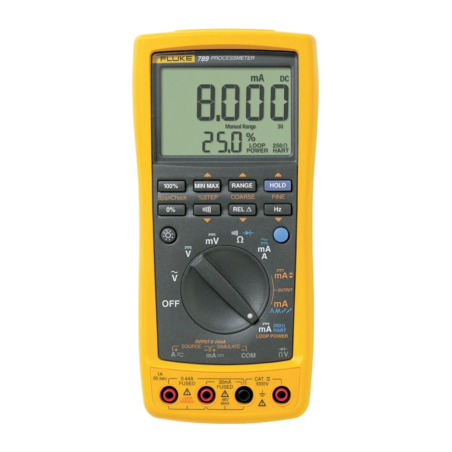
Page 14: Getting Acquainted With The Meter
Users Manual Getting Acquainted with the Meter Figure 4 and Tables 4 and 5 describe the output functions of the last three rotary function switch To become familiar with the features and functions of the positions. meter, study the following figures and tables. Figure 5 and Table 6 describe the functions of the Figure 2 and Table 2 describe the input/output jacks. -
Page 15: Input/Output Jacks
ProcessMeter Getting Acquainted with the Meter Table 2. Input/Output Jacks Source Current Simulate Transmitter Item Jack Measurement Functions Function Function Input for current to 440 mA Output for dc current to 24 mA. continuous. (1 A for up to 30 Output for loop power supply. - Page 16 Users Manual HART LOOP POWER anw002f.eps Figure 3. Rotary Function Switch Positions for Measurements...
-
Page 17: Rotary Function Switch Positions For Measurements
ProcessMeter Getting Acquainted with the Meter Table 3. Rotary Function Switch Positions for Measurements Position Function(s) Pushbutton Actions Meter off Default: Selects a MIN, MAX, or AVG action Measure ac V Selects a fixed range (hold 1 second for auto range) Toggles AutoHold Frequency counter Toggles relative reading (sets a relative zero point) - Page 18 Users Manual HART LOOP POWER anw008f.eps Figure 4. Rotary Function Switch Positions for mA Output...
-
Page 19: Rotary Function Switch Positions For Ma Output
ProcessMeter Getting Acquainted with the Meter Table 4. Rotary Function Switch Positions for mA Output Position Default Function Pushbutton Actions Test leads in % STEP X or W: Adjusts output up or down to the next 25 % step OUTPUT SOURCE: COARSE X or W: Adjusts output up or down 0.1 mA Source 0 % mA... - Page 20 Users Manual 100% MIN MAX RANGE HOLD COARSE SpanCheck %STEP FINE anw003f.eps Figure 5. Pushbuttons...
-
Page 21: Pushbuttons
ProcessMeter Getting Acquainted with the Meter Table 6. Pushbuttons Pushbutton Function(s) Toggles the backlight (low, high, and off) mA Output: Adjusts mA output to 0 % value (4 mA or 0 mA) Span Check mA Output: Sets mA output to 100 % value (20 mA) Span Check Measuring: Selects a MIN, MAX, or AVG action mA Output: Adjusts mA output up to the next higher 25 % step... - Page 22 Users Manual Table 6. Pushbuttons (cont.) Pushbutton Function(s) FINE Measuring: Toggles between frequency counter and voltage measurement functions mA Output: Adjusts output down 0.001 mA Rotary function switch in position and test lead plugged into Ac jack: Toggles between (BLUE) (alternate ac and dc ampere measure Rotary function switch in V position: Toggles diode test function (D)
- Page 23 ProcessMeter Getting Acquainted with the Meter anw004f.eps Figure 6. Elements of the Display...
-
Page 24: Display
Users Manual Table 7. Display Element Meaning Shows the mA measured value or output level in %, in a 0-20 mA or 4-20 mA scale % (Percentage display) (change scales with power-up option) Lights when mA output (source or simulate) is active OUTPUT Lights in continuity function Lights when dangerous voltage is present... - Page 25 ProcessMeter Getting Acquainted with the Meter Table 7. Display (cont.) Meaning Element Show the input or output units and multipliers associated with the numerals mA, DC, mV, AC, M or k , kHz Range status indicators: Auto Range Auto Range - autoranging is on Manual Range Manual Range - the range is fixed 400100030...
-
Page 26: Measuring Electrical Parameters
Users Manual Measuring Electrical Parameters The meter normally selects the lowest range that will measure the applied input signal (Auto Range showing on The proper sequence for taking measurements follows: the display). Press R to lock the range. Each time R is pressed, the meter selects the next higher range. -
Page 27: Displaying Minimum, Maximum, And Average
ProcessMeter Measuring Electrical Parameters Using AutoHold The diode is good if it passes the tests in steps 4 and 5. Note Displaying Minimum, Maximum, and Average MIN MAX recording must be off to use AutoHold. MIN MAX recording stores the lowest and highest ! Warning measurements, and maintains the average of all measurements. -
Page 28: Compensating For Test Lead Resistance
Users Manual Compensating for Test Lead Resistance current in an externally powered current loop, or loop supply mode, where the meter powers an external device Use the relative reading feature (Q on the display) to set and measures the loop current. the present measurement as a relative zero. - Page 29 ProcessMeter Using the Current Output Functions PROCESSMETER MIN MAX RANGE HOLD 100% SpanCheck %STEP COARSE FINE HART LOOP POWER CAT IV 600 V anw010f.eps Figure 7. Sourcing Current...
-
Page 30: Simulate Mode
Users Manual Changing the Current Span Simulate Mode Simulate mode is so named because the meter simulates The meter’s current output span has two settings (with a current loop transmitter. Use simulate mode when an overrange to 24 mA): external dc voltage of 15 to 48 V is in series with the 4 mA = 0 %, 20 mA = 100 % (factory default) current loop under test. -
Page 31: Simulating A Transmitter
ProcessMeter Using the Current Output Functions dc V Power Supply PROCESSMETER +24V 100% MIN MAX RANGE HOLD %STEP COARSE FINE SpanCheck HART LOOP POWER CAT IV 600 V anw011f.eps Figure 8. Simulating a Transmitter... -
Page 32: Producing A Steady Ma Output
Users Manual Producing a Steady mA Output If the meter cannot deliver the programmed current because the load resistance is too high or the loop supply When the rotary function switch is in the OUTPUT [ mA voltage is too low, dashes (-----) appear on the numeric position, and the OUTPUT jacks are connected to an display. -
Page 33: Manually Stepping The Ma Output
ProcessMeter Using the Current Output Functions Manually Stepping the mA Output Table 8. mA Output Adjust Pushbuttons When the rotary function switch is in the OUTPUT [ mA Pushbutton Adjustment position, and the OUTPUT jacks are connected to an appropriate load, the meter produces a steady mA dc Adjusts up 0.1 mA output. -
Page 34: Auto Ramping The Ma Output
Users Manual Table 9. mA Stepping Pushbuttons Table 10. mA Step Values Value (for each span setting) Pushbutton Adjustment Step 4 to 20 mA 0 to 20 mA Adjusts up to the next higher 25 % step 4.000 mA 0.000 mA % STEP 25 % 8.000 mA... -
Page 35: Power-Up Options
ProcessMeter Power-Up Options When the rotary function switch is in the OUTPUT Power-Up Options Y€onp position, and the output jacks are To select a power-up option, hold down the pushbutton connected to an appropriate load, the meter produces a shown in Table 11 while turning the rotary function switch continuously repeating 0 % - 100 % - 0 % ramp in a from OFF to any on position. -
Page 36: Power-Up Options
Users Manual Table 11. Power-Up Options Option Pushbutton Default Action Taken Change current span 0 % setting Remembers Toggles between 0 - 20 mA and 4 - 20 mA last setting range Disable beeper Enabled Disables beeper Disable auto power-off Enabled Disables the feature that turns off the meter (Blue). -
Page 37: Loop Power Supply Mode
ProcessMeter Loop Power Supply Mode Loop Power Supply Mode The Loop Power Supply Mode can be used for powering up a process instrument (transmitter). While in Loop Power Mode, the meter acts like a battery. The process instrument regulates the current. At the same time, the meter measures the current that the process instrument is drawing. - Page 38 Users Manual PROCESSMETER 100% MIN MAX RANGE HOLD SpanCheck %STEP COARSE FINE TEST DC PWR – + – – HART LOOP POWER CAT IV 600 V Black anw009f.eps Figure 10. Connections for Supplying Loop Power...
-
Page 39: Battery Life
Do not disable the automatic power-off feature. Calibrate the meter once a year to ensure that it performs Turn the meter off when not in use. according to its specifications. Contact a Fluke Service Center for instructions. Table 12. Typical Alkaline Battery Life... - Page 40 Users Manual Replacing the Batteries With a standard blade hand screwdriver, turn each battery door screw counterclockwise so that the slot is ! Warning parallel with the screw picture molded into the case. To avoid electrical shock: Lift off the battery door. Remove test leads from the meter before Remove the meter's batteries.
- Page 41 ProcessMeter General Maintenance anw037.eps Figure 11. Replacing the Batteries and Fuses...
-
Page 42: Replacing A Fuse
To avoid personal injury or damage to the meter OFF. meter, use only the specified replacement fuse, 440 mA 1000 V fast-blow, Fluke PN With a standard blade hand screwdriver, turn each 943121. battery door screw counterclockwise so that the slot is parallel with the screw picture molded into the case. -
Page 43: Replacement Parts And Accessories
ProcessMeter Replacement Parts and Accessories If the meter still does not work, contact a Fluke Service Replacement Parts and Accessories Center. If the meter is under warranty, it will be repaired ! Warning or replaced (at Fluke’s option) and returned at no charge. - Page 44 Users Manual anw005f.eps Figure 12. Replacement Parts...
- Page 45 ProcessMeter Replacement Parts and Accessories Table 13. Replacement Parts Reference Item Number Description Fluke PN or Model no. Quantity Designator MP14 Knob Assembly 658440 Top Case with Lens Protector 1622855 Decal, Top Case 1623923 Keypad 1622951 Top Shield 1622924 MP47...
- Page 46 Users Manual Table 13. Replacement Parts (continued) Reference Item Number Description Fluke PN or Model no. Quantity Designator MP50 Shock Absorber 878983 MP11 Bottom Case 659042 MP20 Battery Contact, Negative 658382 BT1-4 Battery, 1.5 V, 0-15 mA, AA Alkaline 376756...
-
Page 47: Specifications
ProcessMeter Specifications Specifications The standard specification interval is 1 year. All specifications apply from +18 C to +28 C unless Note stated otherwise. “Counts” refers to the number of increments or decrements of the least significant digit. All specifications assume a 5-minute warm-up period. DC Volts Measurement Range (V dc) Resolution... - Page 48 Users Manual DC Millivolts Measurement Range (mV dc) Resolution Accuracy, (% of Reading + Counts) 400.0 0. 1 mV 0.1 % + 2 AC Volts Measurement Accuracy, (% of Reading + Counts) Range (ac) Resolution 50 Hz to 60 Hz 45 Hz to 200 Hz 200 Hz to 500 Hz 400.0 mV...
- Page 49 ProcessMeter Specifications AC Current Measurement Range Typical Burden Resolution Accuracy, (% of Reading + Counts) 45 Hz to 2 kHz Voltage 1.000 A (Note) 0.001 A 1 % + 2 1.5 V/A Note: 440 mA continuous, 1 A 30 seconds maximum Specifications are valid from 5 % to 100 % of amplitude range.
- Page 50 Users Manual Ohms Measurement Range Resolution Measurement Current Accuracy, (% of Reading + Counts) 400.0 0. 1 220 A 0.2 % + 2 4.000 k 0.001 k 60 A 0.2 % + 1 40.00 k 0.01 k 6.0 A 0.2 % + 1 400.0 k 0.1 k 600 nA...
- Page 51 ProcessMeter Specifications Frequency Counter Accuracy Range Resolution Accuracy, (% of Reading + Counts) 199.99 Hz 0.01 Hz 0.005 % + 1 1999.9 Hz 0.1 Hz 0.005 % + 1 19.999 kHz 0.001 kHz 0.005 % + 1 Display updates 3 times/second at > 10 Hz Frequency Counter Sensitivity Minimum Sensitivity (rms Sinewave) 5 Hz to 5 kHz*...
- Page 52 Users Manual Diode Test and Continuity Test Simulate Mode: Diode test indication: Displays voltage drop across Span: 0 mA or 4 mA to 20 mA, with overrange to 24 mA device, 2.0 V full scale. Nominal test current 0.2 mA at 0.6 Accuracy: 0.05 % of span V.
- Page 53 ProcessMeter Specifications Accuracy adders for use in RF Fields: In an RF field of ), ! Certifications: To 61010-1 2nd Edition 3 V/m, change the accuracy specifications as follows: ®, ; For AC Volts Measurement, add 0.25 % of range Power requirements: Four AA batteries (alkaline For DC Current Measurement, 30.000 mA range, add recommended)
- Page 54 Users Manual...
Need help?
Do you have a question about the 789 ProcessMeter and is the answer not in the manual?
Questions and answers