Table of Contents
Advertisement
Advertisement
Table of Contents
Troubleshooting

Related Manuals for Scantron iNSIGHT 20


Summary of Contents for Scantron iNSIGHT 20
- Page 1 iNSIGHT Operator’s Guide...
- Page 2 NSIGHT 20 Operator’s Guide...
- Page 3 Copyright © 2009 Scantron Corporation All rights reserved. Printed in the United States of America. For Users in the United States This equipment complies with the requirements in part 15 of FCC Rules for a Class A computing device. Operation of the equipment in a residential area may cause unacceptable interference to radio and television reception requiring the operator to take whatever steps are necessary to correct the interference.
- Page 4 Document Organization This manual is organized as follows: • Chapter 1, “iNSIGHT 20 Dual Purpose Scanner”, provides an overview of the iNSIGHT 20 scanner’s features as well as safety and environmental information. • Chapter 2, “Scanner Basics”, describes the basics of using your scanner.
- Page 5 Web, how to contact Scantron customer support, as well as how to order supplies and forms. Related Documentation This manual is part of a documentation set for the iNSIGHT 20 scanner. The documentation set provides information on packaging, installation, setup, operation, and configuration for users and system administrators. The documentation set consists of the following: •...
-
Page 6: Table Of Contents
Chapter 1: iNSIGHT 20 Dual Purpose Scanner Scanner Hardware Features ......... 3 Data Collection Features . - Page 7 Adjusting the Input Tray Side Guides........30 Scantron iNSIGHT 20 Scanner...
- Page 8 Exit Deflector ............47 Installing the iNSIGHT 20 and iNSIGHT 30 Drivers and Scanner Utilities Software. . 48 Connecting the Power Cord to the Scanner.
- Page 9 Step 1: Calibrating Your iNSIGHT 20 ........
- Page 10 Cleaning the Ultrasonic Multi-feed Detector ......95 Removing and Replacing the Separator Module ......97 Replacing the Separator Module Tires.
- Page 11 Pencil Form Color Combinations (3 Color) ......146 Index Scantron iNSIGHT 20 Scanner...
-
Page 12: Insight 20 Dual Purpose Scanner
Data collection is the process of reading marks from Data Collection printed forms (e.g. surveys, tests, ballots, etc.) and converting them to ASCII data. The iNSIGHT 20 scanner precisely scans the sheets for data while your data collection software (e.g. ScanTools Plus) controls the scanning process and stores the data that is read. - Page 13 (bubbles, check marks, or tick marks) and software bar codes. The iNSIGHT 20 scanner with ScanTools Plus software can also scan grayscale images for digital storage. In addition, the iNSIGHT 20 can read machine print and handprint using RealTime Character Recognition software (available separately).
-
Page 14: Scanner Hardware Features
Chapter 1: iNSIGHT 20 Dual Purpose Scanner Scanner Hardware Features Scanner Hardware Features • Lightweight and portable • Small 30" x 13" x 10.75" (76 x 33 x 27 cm) operational and 6.5" x 13" x 9.5" (16.5 x 33 x 24 cm) storage (trays off) footprints •... -
Page 15: Data Collection Features
Data Collection Features Data Collection Features ScanTools Plus data collection software comes bundled with some iNSIGHT 20 scanners. The following features apply when using ScanTools Plus software. If using other data collection software, consult its documentation for features and limitations. -
Page 16: Document Imaging Features
Chapter 1: iNSIGHT 20 Dual Purpose Scanner Document Imaging Features Document Imaging Features • TWAIN driver and Click&Scan document imaging software included • Scans lengths from 2.5 to 34 in. (6.4 to 86 cm) and widths from 2 to 8.5 in. (5.1 to 21.6 cm) •... -
Page 17: System Requirements
Chapter 1: iNSIGHT 20 Dual Purpose Scanner System Requirements System Requirements The iNSIGHT 20 Drivers and Scanner Utilities NOTE: software supports only one scanner connected to the host computer at a time. For more information about system requirements for the iNSIGHT 20 scanner, go to www.scantron.com/scanners. -
Page 18: Safety Information
Chapter 1: iNSIGHT 20 Dual Purpose Scanner Safety Information Safety Information The scanner and power supply must only be used Caution: indoors in a dry location. • When placing the scanner, make sure that the electrical power outlet is located within 5 feet (1.52 meters) of the scanner and is easily accessible. -
Page 19: Material Safety Data Sheets (Msds)
Chapter 1: iNSIGHT 20 Dual Purpose Scanner Material Safety Data Sheets (MSDS) Material Safety Data Sheets (MSDS) Material Safety Data Sheets (MSDS) for chemical products are available on the Scantron Support Web site at www.scantron.com/support. When accessing the MSDSs from the Web site, you will need the part number for the part or consumable. -
Page 20: Warning Labels
Chapter 1: iNSIGHT 20 Dual Purpose Scanner Warning Labels Warning Labels Moving parts, avoid contact. CAUTION: Hot surface, avoid contact. CAUTION: Operator’s Guide... -
Page 21: User Precautions
Chapter 1: iNSIGHT 20 Dual Purpose Scanner User Precautions User Precautions Users and their employer need to observe the common sense precautions applicable to the operation of any machinery. These include, but are not limited to, the following: • Do not wear loose clothing, unbuttoned sleeves, etc. -
Page 22: Environmental Information
Chapter 1: iNSIGHT 20 Dual Purpose Scanner Environmental Information Environmental Information • The Scantron iNSIGHT 20 scanner is designed to meet worldwide environmental requirements. • Guidelines are available for the disposal of consumable items that are replaced during maintenance or service; follow local regulations or contact your local sales agent for more information. -
Page 23: Emc Statements
Chapter 1: iNSIGHT 20 Dual Purpose Scanner EMC Statements EMC Statements This equipment has been tested and found to comply with United States the limits for a Class B digital device pursuant to Part 15 of the FCC rules. These limits are designed to provide reasonable protection against harmful interference in a residential installation. - Page 24 Chapter 1: iNSIGHT 20 Dual Purpose Scanner EMC Statements This is a Class B product based on the standard of the Japan Voluntary Control Council for interference by information Technology Equipment (VCCI). If this is used near a radio or television receiver in a domestic environment, it may cause radio interference.
-
Page 25: Acoustic Emission
Chapter 1: iNSIGHT 20 Dual Purpose Scanner Acoustic Emission Acoustic Emission Machine Noise Information Ordinance — 3, GSGV The operator-position noise emission value is <70 dB(A). Maschinenlärminformationsverordnung – 3, GSGV Der arbeitsplatzbezogene Emissionswert beträgt <70 db(A). Scantron iNSIGHT 20 Scanner... -
Page 26: Power System Connection
Chapter 1: iNSIGHT 20 Dual Purpose Scanner Power System Connection Power System Connection This product is also designed for Norwegian IT power system with phase-to-phase voltage 230V. Das Gerät ist auch für die Verwendung im norwegischen Netzanschluß IT-Stromsystem mit einer Leiterspannung von 230 V geeignet. - Page 27 Chapter 1: iNSIGHT 20 Dual Purpose Scanner Power System Connection Scantron iNSIGHT 20 Scanner...
-
Page 28: Chapter 2: Scanner Basics
Chapter 2: Scanner Basics This chapter covers basic information about your iNSIGHT 20 scanner that you should know before installing and using your scanner. The information covered in this chapter will familiarize you with the scanner so that you can successfully scan documents during setup and for production use. -
Page 29: Scanner Components
Output Tray Extender — A two piece tray extender that extends the output tray up to 15 in. (38 cm). LED Indicator — Illuminates or flashes indicating scanner status. • Steady Green: Ready to scan. Scantron iNSIGHT 20 Scanner... - Page 30 Chapter 2: Scanner Basics Scanner Components • Flashing Green: Waiting/power saver mode/ scanning/busy. • Steady Red: Scanner error (such as the scanner is not connected to the host computer or the scanner cover is open). NOTE: The Start Button, Scroll Button and Function Window are used with the Click&Scan functionality.
-
Page 31: Inside View
Separation Module Release Lever — Push the release lever to remove the separation module for cleaning or replacement. Scanner Cover Release Lever — Opens the scanner to allow access to the paper path for cleaning or clearing a document jam. Scantron iNSIGHT 20 Scanner... -
Page 32: Back View
Chapter 2: Scanner Basics Scanner Components Gap Release Lever — Allows you to manually adjust the space between the feed module and separation module for documents that require special handling. Rollers — Provide smooth document feeding. Ultrasonic Multi-feed Detection Sensor — Uses sound waves to detect multi-feeds. -
Page 33: Locking The Scanner
Insert the lock into the back of the scanner and turn the key to lock the scanner in place. Use the looped end of the cable to secure the cable and scanner to a stationary place. Scantron iNSIGHT 20 Scanner... -
Page 34: Turning The Scanner On
Chapter 2: Scanner Basics Turning the Scanner On Turning the Scanner On Do not turn the scanner on before performing CAUTION: the installation procedure covered in Chapter 3, “Installation”. Doing so may result in incorrect driv- ers being loaded. Press the switch on the back of the scanner to turn the scanner on (l) or off (0). -
Page 35: Scanner Positions
Chapter 2: Scanner Basics Scanner Positions Scanner Positions The iNSIGHT 20 scanner is equipped with a tilt feature which allows the scanner to be tilted in two different positions. Depending upon your scanning needs, you can tilt the scanner body and adjust the output tray and extender accordingly. - Page 36 Chapter 2: Scanner Basics Scanner Positions 60 degree position This position is best for storage or for scanning just a few sheets. When scanning just a few sheets, do not use the output tray as shown above. See “Output Tray Extender Flat”...
-
Page 37: Tilting The Scanner Body
Chapter 2: Scanner Basics Tilting the scanner body Tilting the scanner body Press the Tilt release button and rotate the scanner body into the desired position. Scantron iNSIGHT 20 Scanner... -
Page 38: Adjusting The Output Tray And Output Tray Extender
Chapter 2: Scanner Basics Adjusting the Output Tray and Output Tray Extender Adjusting the Output Tray and Output Tray Extender The output tray and the output tray extender can be used in several positions. Different positions perform for different needs. If the way you use your scanner is not described in this section, experiment with different positions to determine the one that best fits your needs. -
Page 39: Output Tray Extender Flat
It is recommended when using the scanner in the 60 degree position. To remove the tray extender from this position, press on the two side tabs and pull. Output Tray Extender on Incline This position also works well for small batches of documents. Scantron iNSIGHT 20 Scanner... -
Page 40: Exit Deflector
Chapter 2: Scanner Basics Adjusting the Output Tray and Output Tray Extender Exit Deflector You can often improve your document stacking performance by using the exit deflector. To find the optimal setup, experiment by scanning with the exit deflector on and off. The exit deflector is easily installed by snapping it into place. -
Page 41: Adjusting The Input Tray Side Guides
Adjusting the Input Tray Side Guides Adjusting the Input Tray Side Guides The input tray side guides can be moved in or out to accommodate different document sizes. Adjust the side guides just slightly wider than the documents you are scanning. Scantron iNSIGHT 20 Scanner... -
Page 42: Starting And Stopping The Scanner
Chapter 2: Scanner Basics Starting and Stopping the Scanner Starting and Stopping the Scanner Before you start scanning, make sure the scanner is on and ready for operation, which is indicated by the green indicator light being on and constant. Scanning is controlled by software developed for your application. -
Page 43: Document Preparation
(because it is a bottom feed scanner). Also ensure that the timing marks are on the left side (both front and back) when you are facing the Scantron logo. Timing Marks Scantron iNSIGHT 20 Scanner... -
Page 44: Document Imaging
Chapter 2: Scanner Basics Document Preparation • Paper Types: Precision forms printed by Scantron are recommended for best results. Self printed forms using Scantron DesignExpert with the PrintFlex option are also acceptable. • Paper Weights: 60 - 90 lb., (24 - 35 lb. bond), (89 - 133 g/m •... - Page 45 • Paper Types: The iNSIGHT 20 moves paper very well and will handle virtually any type of paper that is not abrasive or excessively stiff.
-
Page 46: Scanning Your Documents
Chapter 2: Scanner Basics Scanning Your Documents Scanning Your Documents Place the documents you want to scan into the input tray of the scanner with the front side down (because it is a bottom feed scanner). Automatic Feeding To scan a batch of documents, follow the guidelines for size, type, quantity, etc., as previously described in “Document Preparation”... -
Page 47: Single Feeding
Follow the guidelines for document size, type, weight, quantity, etc. Position the document face down with the leading edge centered in the automatic document feeder, adjust the input tray side guides if necessary, then start scanning. Scantron iNSIGHT 20 Scanner... -
Page 48: Indicator Light
Chapter 2: Scanner Basics Indicator Light Indicator Light The indicator light provides information on the current state of the scanner. Indicator Light This light… indicates… Flashing green scanner is powering up, busy, or in power saver mode. Steady green scanner is ready to scan. Steady red scanner error, such as the scanner is not... -
Page 49: Lamps
Lamps Default Lamp Shut Off Period The default shut off period for the lamps is 15 minutes. The iNSIGHT 20 scanner reverts to this default each time it is powered up. Software Lamp Warm Up and Shut Off Periods Lamp warm up and shut off periods vary depending on the software that you are using. -
Page 50: Clearing Document Jams
Chapter 2: Scanner Basics Clearing Document Jams Clearing Document Jams Remove any documents from the input tray area. Lift up the scanner cover release to unlatch the scanner cover. Pull up to open the scanner cover. Scanner Cover Release Locate the jammed document and remove it, being sure to clear any paper shreds or pieces left behind. - Page 51 Chapter 2: Scanner Basics Clearing Document Jams Lower the scanner cover and press it down firmly so that both sides latch. Scantron iNSIGHT 20 Scanner...
-
Page 52: Chapter 3: Installation
Attaching the Input Tray....page 44 Installing the iNSIGHT 20 and iNSIGHT 30 Drivers and Scanner Utilities Software ... . page 48 Getting Ready to Scan. -
Page 53: Selecting A Good Location
The outlet must be properly grounded and meet national and local electrical codes. • Space. Find a location that allows you plenty of working surface around the scanner. See “Scanner Hardware Features” on page 3 for information on the scanner’s size. Scantron iNSIGHT 20 Scanner... - Page 54 Chapter 3: Installation Selecting a Good Location • Temperature. Place the scanner in an environment that ranges between 60° and 85° Fahrenheit or 15º to 29º Celsius. Improper temperature conditions can cause the scanner to read sheets incorrectly. Operator’s Guide...
-
Page 55: Attaching The Input Tray
Next, push the input tray gently but firmly toward the other side, so that the pin on the other side has clearance to fit in the hole on the other side. Allow the input tray to rotate down into position. Scantron iNSIGHT 20 Scanner... -
Page 56: Attaching The Output Tray And Output Tray Extender
Chapter 3: Installation Attaching the Output Tray and Output Tray Extender Attaching the Output Tray and Output Tray Extender This section covers attaching the output tray and output tray extender. For information on how to adjust them, see “Adjusting the Output Tray and Output Tray Extender” starting on page 27. - Page 57 (a top and a bottom). For best results, slide the bottom piece out so that the entire length of the output tray assembly is a little longer than the sheets you are scanning. Scantron iNSIGHT 20 Scanner...
-
Page 58: Exit Deflector
Chapter 3: Installation Attaching the Output Tray and Output Tray Extender Exit Deflector When using the output tray extender and scanning smaller documents or mixed sized documents, you can improve your document stacking performance by using the exit deflector. The exit deflector is easily installed by snapping it into place. -
Page 59: Installing The Insight 20 And Insight 30 Drivers And Scanner Utilities Software
Chapter 3: Installation Installing the iNSIGHT 20 and iNSIGHT 30 Drivers and Scanner Utilities Software Installing the iNSIGHT 20 and iNSIGHT 30 Drivers and Scanner Utilities Software before Install the software connecting the scan- CAUTION: ner to the PC. The iNSIGHT 20 and iNSIGHT 30 Drivers and... - Page 60 Chapter 3: Installation Installing the iNSIGHT 20 and iNSIGHT 30 Drivers and Scanner Utilities Use the following procedure to install the software and connect the scanner. Insert the iNSIGHT 20 and iNSIGHT 30 Drivers and Scanner Utilities CD into the CD-ROM drive.
- Page 61 Chapter 3: Installation Installing the iNSIGHT 20 and iNSIGHT 30 Drivers and Scanner Utilities Software Click Next to continue. The Choose Destination Location dialog box appears. Accept the default location or enter a destination for the program files in the text box. Click Next to continue.
-
Page 62: Connecting The Power Cord To The Scanner
Chapter 3: Installation Installing the iNSIGHT 20 and iNSIGHT 30 Drivers and Scanner Utilities Accept the default or enter a program folder in the text box. Click Next to continue. The Setup Status dialog box appears and displays the installation progress. -
Page 63: Power Supply
Chapter 3: Installation Installing the iNSIGHT 20 and iNSIGHT 30 Drivers and Scanner Utilities Software Select the appropriate AC power cord for your region from the supply of power cords packed with your scanner. M4206 V301C AU10S2 M733F Australia Europe... -
Page 64: Connecting The Usb Cable
Chapter 3: Installation Installing the iNSIGHT 20 and iNSIGHT 30 Drivers and Scanner Utilities Plug the power cord output lead (attached to the power supply) into the power port on the back of the scanner. Plug the power cord input lead (attached to the power supply) into the wall outlet. - Page 65 Chapter 3: Installation Installing the iNSIGHT 20 and iNSIGHT 30 Drivers and Scanner Utilities Software The USB cable supplied with your scanner has two different ends. Attach the B end of the USB cable to the scanner USB port, located on the back of the scanner.
-
Page 66: Finalizing The Insight 20 Drivers And Scanner Utilities Software Installation
Chapter 3: Installation Installing the iNSIGHT 20 and iNSIGHT 30 Drivers and Scanner Utilities Finalizing the iNSIGHT 20 Drivers and Scanner Utilities Software Installation When the iNSIGHT 20 and iNSIGHT 30 Drivers and Scanner Utilities software has been properly installed and the USB cable and power connections have been made, you can turn on the power to complete installation. - Page 67 Chapter 3: Installation Installing the iNSIGHT 20 and iNSIGHT 30 Drivers and Scanner Utilities Software The scanner will go through a series of self tests, and the indicator LED will light. When the scanner is finished and ready to scan, the indicator LED will stop flashing and stay green.
- Page 68 Chapter 3: Installation Installing the iNSIGHT 20 and iNSIGHT 30 Drivers and Scanner Utilities The Select Option dialog box appears. Do not click Exit. Continue following the steps in the next section to get ready to start scanning. Operator’s Guide...
-
Page 69: Getting Ready To Scan
Once the hardware is connected and the drivers are installed, perform the following to get ready to scan documents: • Step 1: Calibrating Your iNSIGHT 20 (page 58) • Step 2: Running the Document Imaging Test (page 64) If your scanner came bundled with ScanTools Plus data... - Page 70 Chapter 3: Installation Getting Ready to Scan • Targets the location of the black dots for position- ing purposes. The calibration program reads Normalization & Calibration sheets (supplied with the scanner, see photo below). The part number for a box of 80 Normalization & NOTE: Calibration Sheets is 342 760 014.
- Page 71 Click Calibrate. The Step 1 of 2... dialog box appears. Place a stack of Normalization & Calibration Sheets (part number 202 502 043) into the input tray, printed side down, so that the words “Normalization & Scantron iNSIGHT 20 Scanner...
- Page 72 Chapter 3: Installation Getting Ready to Scan Calibration Sheet” enter the scanner first, as shown in the photo below. Corner turned to show printed side only. NOTE. Click OK. If the lamps have been off, the Lamps warming up... dialog box appears. Please wait while the lamps warm up. When the lamps have warmed up, the Calibrating front/top camera...
- Page 73 When front side calibration is complete, the Step 2 of 2... dialog box appears. Place a stack of Normalization & Calibration Sheets (part number 202 502 043) into the input tray, printed side up, and so that the words “Normalization & Cali- Scantron iNSIGHT 20 Scanner...
- Page 74 Chapter 3: Installation Getting Ready to Scan bration Sheet” enter the scanner last (as shown in the photo below). Click OK. The Calibrating back/bottom camera... dialog box appears. Please wait while the software performs back side calibration. When back side calibration is complete, the Verifying calibration...
-
Page 75: Step 2: Running The Document Imaging Test
To do this, from the switchboard shown below, click Run Document Imaging Test. If you are no longer at the above screen, start the NOTE: Scan Validation Tool by selecting StartProgramsScantronDocument ImagingScan Validation Tool. Scantron iNSIGHT 20 Scanner... - Page 76 Chapter 3: Installation Getting Ready to Scan The Scan Validation Tool dialog box appears. Select TWAIN and Scantron iNSIGHT 20 as shown. Click The Connecting to Scanner message box appears, indicating that it may take a few minutes to connect to the scanner.
- Page 77 Chapter 3: Installation Getting Ready to Scan The Scan Validation Tool appears. Click the two- image display button (shown in the margin). Click the Setup button (shown in the margin). Scantron iNSIGHT 20 Scanner...
- Page 78 Chapter 3: Installation Getting Ready to Scan The main iNSIGHT 20 settings window appears. Under Setting Shortcuts select Color Docu- ment Under Input document is, ensure that Two Sided is selected. Click OK. The Scan Validation Tool window reappears. Place a two sided color document in the input tray, then click the Start Scanning button (shown in the margin).
-
Page 79: Step 3: Installing Scantools Plus Software
30 Drivers and Scanner Utilities installed before installing ScanTools Plus. Next, install ScanTools Plus data collection software. See Chapter 2 of the ScanTools Plus User’s Guide (included with your iNSIGHT 20 scanner) for instructions on how to install the software. Step 4: Configuring the Scanner IMPORTANT: Perform this step only if your scanner came bundled with ScanTools Plus data collection software. -
Page 80: Step 5: Running The Data Collection Test
Select ConfigureScanner Configuration... from the ScanTools Plus menu. The Scanner Configuration dialog box appears. Select iNSIGHT 20 for the Scanner Model. Make sure that Write Operations Log is selected. Click the Auto Configure button. If you get an error, contact Scantron Customer Sup- port as described in “Requesting Support”... - Page 81 Chapter 3: Installation Getting Ready to Scan • the iNSIGHT 20 Scanner Utilities. In this section you will use ScanTools Plus software to perform data collection. If it is not already running, start ScanTools Plus by selecting StartProgramsScantronScanTools Plus. The ScanTools Plus window appears.
- Page 82 Chapter 3: Installation Getting Ready to Scan program, select ConfigurePaths. For the application path, browse to C:\Program Files\Scantron\ScanTools Plus\Applications. Click OK, then try to select the application again. If this does not resolve the issue, contact Scantron Customer Support as described in “Requesting Support”...
- Page 83 If you are unable to resolve the difficulty, contact Scantron Customer Support as described in “Requesting Support” on page 125. When the scanner is done scanning, the following dialog box appears indicating that the input hopper is Scantron iNSIGHT 20 Scanner...
- Page 84 Chapter 3: Installation Getting Ready to Scan empty. Click Stop to clear the dialog boxes so that you can view the data file. Select Data FileView in the ScanTools Plus menu bar to review the data file. The data file appears. Use the up and down buttons (shown in the margin) next to the Serial Number text box to page through the Name data for each sheet.
-
Page 85: Installation Complete
If data appears incorrect or is missing, contact Scant- ron Customer Support as described in “Requesting Support” on page 125. Installation Complete Installation is now complete. Please be sure to famil- iarize yourself with the rest of the information in this guide. Scantron iNSIGHT 20 Scanner... -
Page 86: Handling The "Recalibrate The Scanner" Message
To do this, follow the procedure below: Select StartProgramsScantroniNSIGHT 20 Scanner UtilitiesCalibration Utility. Go to the section entitled “Step 1: Calibrating Your iNSIGHT 20” on page 58, and follow the procedure there to recalibrate the scanner. Operator’s Guide... -
Page 87: Uninstalling Insight 20 And Insight 30 Drivers And Scanner Utilities Software
Chapter 3: Installation Uninstalling iNSIGHT 20 and iNSIGHT 30 Drivers and Scanner Utilities Software Uninstalling iNSIGHT 20 and iNSIGHT 30 Drivers and Scanner Utilities Software Perform the following steps only if you want to NOTE: uninstall the software. If you want to uninstall the drivers and scanner utilities... -
Page 88: Uninstalling Scantools Plus Software
Chapter 3: Installation Uninstalling iNSIGHT 20 and iNSIGHT 30 Drivers and Scanner Utilities Uninstalling ScanTools Plus Software This procedure is applicable only if your scan- IMPORTANT: ner came bundled with ScanTools Plus data collection software. If you want to uninstall the ScanTools Plus software, see Chapter 2 of the ScanTools Plus User’s Guide (included with... -
Page 89: Updating The Insight 20 And Insight 30 Drivers And Scanner Utilities Software
Chapter 3: Installation Updating the iNSIGHT 20 and iNSIGHT 30 Drivers and Scanner Utilities Software Updating the iNSIGHT 20 and iNSIGHT 30 Drivers and Scanner Utilities Software It is important to turn the scanner off during the CAUTION: software update because the new firmware is loaded into the scanner upon power up. - Page 90 Chapter 3: Installation Updating the iNSIGHT 20 and iNSIGHT 30 Drivers and Scanner Utilities 20 and iNSIGHT 30 Drivers and Scanner Utilities Software” on page 48 for instructions on a complete re-installation. Click Update/Repair iNSIGHT 20 and iNSIGHT 30 Drivers and Scanner Utilities. The Question message box appears.
- Page 91 Chapter 3: Installation Updating the iNSIGHT 20 and iNSIGHT 30 Drivers and Scanner Utilities Software NOTES Scantron iNSIGHT 20 Scanner...
- Page 92 In this chapter: Maintenance Schedule..... page 83 Supplies and Consumables ....page 85 Opening and Closing the Scanner Cover.
- Page 93 • If a difficulty persists after performing the maintenance recommended in this manual, call Scantron Customer Support as described in “Requesting Support” on page 125. Scantron iNSIGHT 20 Scanner...
-
Page 94: Maintenance Schedule
Chapter 4: Maintenance Maintenance Schedule Maintenance Schedule Use the following table as a guide to routine maintenance. Usage figures are not guaranteed. Customer-operating environments, document type, the condition of documents being scanned, and not following the recommended cleaning and replacement procedures, can cause the life of the consumables to vary. - Page 95 Certain paper types (such as carbonless paper or NOTE: newsprint), failure to clean regularly, and/or use of non-recommended cleaning solvents can shorten tire and roller life. Scantron iNSIGHT 20 Scanner...
-
Page 96: Supplies And Consumables
Chapter 4: Maintenance Supplies and Consumables Supplies and Consumables See “Ordering Supplies” on page 133 for information on how to order supplies. Supplies/Consumables Purpose Part Number Consumables Kit (12 feed Provides commonly needed 20190 tires, 1 pre-separation pad, 50 wear parts and cleaning transport cleaning sheets, 24 supplies emulsiclean wipes, 144... - Page 97 When accessing the MSDSs from the Web site, you will need the part number for the part or consumable. See “Supplies and Consumables” on page 85 of this guide for a list of consumables and their part numbers. Scantron iNSIGHT 20 Scanner...
-
Page 98: Opening And Closing The Scanner Cover
Chapter 4: Maintenance Opening and Closing the Scanner Cover Opening and Closing the Scanner Cover Power down the scanner if desired. It is sometimes helpful to have the lamps on NOTE: when cleaning the imaging guide areas. Remove any documents from the feeder area. Place the scanner in the 25 degree position. - Page 99 Chapter 4: Maintenance Opening and Closing the Scanner Cover When you finish cleaning the scanner or replacing a part, press down firmly on scanner cover as shown so that both sides latch. Scantron iNSIGHT 20 Scanner...
-
Page 100: Running A Transport Cleaning Sheet
Chapter 4: Maintenance Running a Transport Cleaning Sheet Running a Transport Cleaning Sheet The scanner must be closed and powered on to run a NOTE: transport cleaning sheet. Remove the wrapping from the Transport Cleaning Sheet. Adjust the side guides to fit the cleaning sheet. Place a transport cleaning sheet in the input tray (adhesive side up) in portrait orientation. -
Page 101: Cleaning The Rollers And Transport
Do not use the emulsiclean wipe on the gray foam tires Dry the rollers with a lint-free cloth such as a dry emulsiclean wipe. Do not use a paper towel as this will introduce dust into the transport area. Scantron iNSIGHT 20 Scanner... -
Page 102: Cleaning The Separator Module
Chapter 4: Maintenance Cleaning the Separator Module Cleaning the Separator Module The separator module should be removed from the scanner for best cleaning results. Remove and inspect the separator module as described in steps 1 through 3 of “Removing and Replacing the Separator Module”... -
Page 103: Cleaning The Feed Module
Remove and inspect the feed module as described in steps 1 through 4 of “Removing and Replacing the Feed Module” on page 105. Manually rotate and wipe the gray foam tires with a slightly damp staticide wipe (part number 830 9783). Scantron iNSIGHT 20 Scanner... - Page 104 Chapter 4: Maintenance Cleaning the Feed Module If the wipe contains too much liquid, squeeze it out or let it dry out for a couple minutes before using. Install the feed module as described in steps 5 through 7 of “Removing and Replacing the Feed Module” on page 105.
-
Page 105: Cleaning The Imaging Guides
(part number 830 9783). Staticide Wipe Dry the upper and lower imaging guides using a dry staticide wipe. Do not use a paper towel or dry emulsiclean wipe as this will introduce static. When finished, close the scanner cover. Scantron iNSIGHT 20 Scanner... -
Page 106: Cleaning The Ultrasonic Multi-Feed Detector
Chapter 4: Maintenance Cleaning the Ultrasonic Multi-feed Detector Cleaning the Ultrasonic Multi-feed Detector Do not use canned air to clean the ultrasonic CAUTION: multi-feed detector transmitter and receiver as this could blow debris into difficult to clean areas of the scanner. - Page 107 Lower the scanner cover and press it down firmly until both sides latch. Test the scanner to ensure that the scanner is functioning properly. If it is not, call Scantron Customer Support as described in “Requesting Support” on page 125. Scantron iNSIGHT 20 Scanner...
-
Page 108: Removing And Replacing The Separator Module
Chapter 4: Maintenance Removing and Replacing the Separator Module Removing and Replacing the Separator Module Pull on the separator module as shown to snap it out. Lift it out of position. Inspect the separator module. If the separator module tires show signs of wear or damage, replace the tires or the separator module as described in “Replacing the Separator Module Tires”... - Page 109 Chapter 4: Maintenance Removing and Replacing the Separator Module Insert the separator module by aligning the pins with the slots and pressing it into position until it latches on both sides. Slot Scantron iNSIGHT 20 Scanner...
-
Page 110: Replacing The Separator Module Tires
Chapter 4: Maintenance Replacing the Separator Module Tires Replacing the Separator Module Tires Remove and inspect the separation module as described in steps 1 through 2 of “Removing and Replacing the Separator Module” on page 97. Holding onto the separation module, rotate the release lever back so you can access the separation roller. - Page 111 Replace the separation roller in the separation roller housing. Be sure the separation roller snaps into place. Re-install the separation module as described in step 3 of “Removing and Replacing the Separator Module” on page 97. Scantron iNSIGHT 20 Scanner...
-
Page 112: Replacing The Pre-Separation Pad
Chapter 4: Maintenance Replacing the Pre-Separation Pad Replacing the Pre-Separation Pad Remove and inspect the separation module as described in steps 1 through 2 of “Removing and Replacing the Separator Module” on page 97. Hold the separator module in both hands and find the two preseparation pad side tabs which protrude slightly from the back of the separation module. - Page 113 Push the pre-separation pad firmly in the slots until the pre-separation pad flap rests lightly against the separation module tires. Re-install the separation module as described in step 3 of “Removing and Replacing the Separator Module” on page 97. Scantron iNSIGHT 20 Scanner...
-
Page 114: Adjusting The Pre-Separation Roller Tension
Chapter 4: Maintenance Adjusting the Pre-Separation Roller Tension Adjusting the Pre-Separation Roller Tension If you are experiencing multi-feeds or document jams, it may be necessary to adjust the pre-separation roller tension. Remove and inspect the separation module as described in steps 1 through 3 of “Removing and Replacing the Separator Module”... - Page 115 Lift the spring from the holder and move it to the left or right as desired to adjust the tension. When finished, re-install the separation module as described in step 4 of “Removing and Replacing the Separator Module” on page 97. Scantron iNSIGHT 20 Scanner...
-
Page 116: Removing And Replacing The Feed Module
Chapter 4: Maintenance Removing and Replacing the Feed Module Removing and Replacing the Feed Module Degradation of feeder performance, multiple feeds, stoppages, etc. indicate a need to change the feed module. Certain paper types such as carbonless paper or newsprint, or failure to clean regularly, and/or use of non- recommended cleaning solvents can shorten the feed module life. - Page 117 Inspect the feed module. If the feed module tires show signs of wear or damage, replace the tires as described in “Replacing the Feed Module Tires” on page 108. If other parts appear worn or damaged, replace the feed module with a new one. Scantron iNSIGHT 20 Scanner...
- Page 118 Chapter 4: Maintenance Removing and Replacing the Feed Module Using a vacuum or emulsiclean wipe, remove dust and debris from the feed module area. Insert the feed module by aligning the pins and pushing it toward the left to fit it into position. Be sure the gears are aligned and it snaps into place.
-
Page 119: Replacing The Feed Module Tires
Paper Present Sensor Remove and inspect the feed module as described in steps 1 through 4 of “Removing and Replacing the Feed Module” on page 105. Scantron iNSIGHT 20 Scanner... - Page 120 Chapter 4: Maintenance Replacing the Feed Module Tires Remove one core assembly by lifting up and out of position. Remove each tire by sliding the tire off the core. Install each new tire by gently pulling it over the core. IMPORTANT: Do not overstretch the tire;...
- Page 121 Replacing the Feed Module Tires Repeat the replacement procedure outlined above for the other core assembly. Install the feed module as described in steps 5 through 7 of “Removing and Replacing the Feed Module” on page 105. Scantron iNSIGHT 20 Scanner...
-
Page 122: Chapter 5: Troubleshooting
In this chapter: Indicator Light and Function Window ..page 112 Lamps ....... . page 114 Clearing Document Jams . -
Page 123: Indicator Light And Function Window
Flashing green scanner is busy or in power saver mode Flashing red scanner failure Steady red with a 0 scanner is not connected to the host Steady red with a 1-5, 7, or 8 call Customer Support Scantron iNSIGHT 20 Scanner... - Page 124 Chapter 5: Troubleshooting Indicator Light and Function Window This light (and function indicate(s)… window)… Steady red with a 6 scanner cover is open Steady red with a 9 document jam The numbers 1-9 may be displayed when the scan- NOTE: ner’s LED is green.
-
Page 125: Lamps
Device Setting set to the desired shut off time. TIP: Use ScanTools to scan a sheet ahead of time, so that you don’t have to wait for the lamps to warm up when you are ready to start scanning for data collection. Scantron iNSIGHT 20 Scanner... -
Page 126: Clearing Document Jams
Chapter 5: Troubleshooting Clearing Document Jams Clearing Document Jams If your scanner stops scanning due to a document jam, follow the procedures below. Open the scanner cover. Scanner Cover Release Remove any jammed documents from inside the scanner. Close the cover. Operator’s Guide... -
Page 127: Troubleshooting Chart
Chapter 5: Troubleshooting Troubleshooting Chart Troubleshooting Chart Use the chart below as a guide to check possible for solutions to problems you may encounter when using the Scantron iNSIGHT 20 Scanner. Problem Possible Solution The scanner will not scan/ Make sure that: feed documents •... - Page 128 Chapter 5: Troubleshooting Troubleshooting Chart Problem Possible Solution “False” paper jams Check that the ultrasonic multi-feed detector are occurring transmitter and receiver are clean. Debris in these areas can cause a paper jam error when no documents have been fed. To clean, refer to “Cleaning the Ultrasonic Multi-feed Detector”...
- Page 129 Make sure that the input and output tray extenders feeding or are jamming are pulled out to provide support for during document imaging long documents. See “Adjusting the Output Tray and Output Tray Extender” starting on page 27 for details. Scantron iNSIGHT 20 Scanner...
- Page 130 Chapter 5: Troubleshooting Troubleshooting Chart Problem Possible Solution Image quality is poor or Make sure that the scanner is clean. See has decreased during “Maintenance” on page 81. document imaging Lines appear on the image Clean the imaging guides. See “Cleaning the during document imaging Imaging Guides”...
-
Page 131: The Scan Validation Tool Diagnostics Window
ImagingScan Validation Tool. The Scan Valida- tion Tool dialog box appears. Drive Types: TWAIN and Drivers: Scantron iNSIGHT 20 are already selected. Click OK to continue. The Scan Validation Tool appears. Click the Setup button (shown in the margin). The main iNSIGHT 20 scanner (TWAIN Driver) window appears. -
Page 132: Diagnostics - General Tab
This test is automatically turned off when the NOTE. scanning application disconnects from the scanner. This feature is not relevant to the iNSIGHT 20 scanner Scanner Time because it does not have a printer option. Operator’s Guide... -
Page 133: Diagnostics - Component Tab
Chapter 5: Troubleshooting The Scan Validation Tool Diagnostics Window Diagnostics - Component Tab The Component tab lists the status of a number of scanner components. Scantron iNSIGHT 20 Scanner... -
Page 134: Diagnostics - Debug Tab
Chapter 5: Troubleshooting The Scan Validation Tool Diagnostics Window Diagnostics - Debug Tab The Debug tab allows you to store the communications between the scanner and a scanning application, as well as the images, to a file that can be reviewed later by Customer Support. - Page 135 Sent To Application: normally, you do not need to save the images received at the scanning application from the scanner. We recommend that you only turn this on when instructed by Customer Support. • Not used unless instructed by Customer Support. Simulation Scantron iNSIGHT 20 Scanner...
-
Page 136: Diagnostics - Logs Tab
Chapter 5: Troubleshooting The Scan Validation Tool Diagnostics Window Diagnostics - Logs Tab The Logs tab allows you to view scanner information. • General: displays the scanner’s version information, Logs serial number, attached/installed accessories, meters, etc. • Operator: displays the scanner’s log. This log can only be cleared by Customer Support. - Page 137 Chapter 5: Troubleshooting The Scan Validation Tool Diagnostics Window NOTES Scantron iNSIGHT 20 Scanner...
-
Page 138: Product Support And Services
In this chapter: Registering Your Product ....page 127 Printed Documentation ....page 129 The Help System. -
Page 139: Online Registration
If you are entitled to updates or upgrades, you may NOTE: obtain them on physical media for an extra fee. Online Registration Go to the Scantron Web site at www.scantron.com. Select SupportProduct Registration. The Product Registration page will appear. Follow the on-screen instructions. Scantron iNSIGHT 20 Scanner... -
Page 140: Printed Documentation
The printed documentation set for the iNSIGHT 20 consists of the following: • What’s in This Box for the iNSIGHT 20 Scanner (Publica- tion Number 277 160 xxx*) • Quick Start for the iNSIGHT 20 Scanner (Publication Number 277 158 xxx*) •... -
Page 141: The Help System
Chapter 6: Product Support and Services The Help System The Help System Your iNSIGHT 20 scanner does not come with a Help system specifically for the hardware. However, the Scantron software products that you use with your scanner each come with a Help system that includes comprehensive information that may help you with your hardware issues. -
Page 142: Training
Chapter 6: Product Support and Services Training Training Contact your local sales agent for training information. Outside the U.S. While Scantron does not offer training specifically for Within the U.S. your scanner hardware, we do offer training on most Scantron software products used with your scanner. Training is available for: ®... -
Page 143: Internet Resources
New licensees of Scantron software products have NOTE: access to these support resources. Continued access to some of these resources requires a continuing software subscription support agreement. Scantron iNSIGHT 20 Scanner... -
Page 144: Ordering Supplies
Chapter 6: Product Support and Services Ordering Supplies Ordering Supplies Contact your local sales agent to order supplies. Outside the U.S. We offer quick, easy access to supplies and user manuals Within the U.S. for your Scantron scanner and software. You can order online or by phone or fax: Online Phone or Fax... -
Page 145: Ordering Forms And Print Services
Other services available through Scantron Print Services include background form images, merge template creation, high volume merge printing projects, and delivery and fulfillment services. Phone or Fax Scantron Print Services Phone 1-800-735-2566 Fax 1-717-684-1300 Scantron iNSIGHT 20 Scanner... -
Page 146: Requesting Support
7:00 P.M. CST). Before calling: Know the serial number of the product you are calling about. The serial number for your iNSIGHT 20 can be found on the bottom of the scanner. Write down a description of your problem. Include a sequence of the steps leading to the problem. - Page 147 • Installation and configuration • Program features and operation • Scanner and software troubleshooting • Documentation and the Help system • Fonts and graphics • Software/hardware errors • Laser printing forms • ScanFlex and PrintFlex Scantron iNSIGHT 20 Scanner...
-
Page 148: Services
Chapter 6: Product Support and Services Services Services Contact your local sales agent for services information. Outside the U.S. A variety of services are available including custom data Within the U.S. collection solutions, survey research services, equipment maintenance, equipment installation, network installation, custom training solutions, custom application development, database support, software support for custom applications, and consulting services. - Page 149 Chapter 6: Product Support and Services Services NOTES Scantron iNSIGHT 20 Scanner...
-
Page 150: Color Options For Data Collection Forms
In this chapter: Ink Form Color Options (1 Color) ..page 140 Pencil Form Color Options (1 Color) ..page 141 Pencil Form Color Combinations (2 Color) . . page 142 Pencil Form Color Combinations (3 Color) . -
Page 151: Ink Form Color Options (1 Color)
Choose a single ink dropout color for your form from the colors below. Drop Out Colors Carnival Fiesta Harvest Pumpkin Raspberry Rose Spice Strawberry Tangerine NOTE: There are no two or three color combinations for ink read forms. Scantron iNSIGHT 20 Scanner... -
Page 152: Pencil Form Color Options (1 Color)
Appendix A: Color Options for Data Collection Forms Pencil Form Color Options (1 Color) Pencil Form Color Options (1 Color) Choose a single pencil dropout color for your form from the colors below. Drop Out Colors Anchor Caribbean Carnival Cherry Fiesta Frost Harvest... -
Page 153: Pencil Form Color Combinations (2 Color)
Rose Anchor Rust Anchor Spice Anchor Strawberry Anchor Tangerine Anchor Woodland Caribbean Carnival Caribbean Cherry Caribbean Fiesta Caribbean Harvest Caribbean Caribbean Pumpkin Caribbean Raspberry Caribbean Rose Caribbean Rust Caribbean Spice Caribbean Strawberry Caribbean Tangerine Caribbean Woodland Scantron iNSIGHT 20 Scanner... - Page 154 Appendix A: Color Options for Data Collection Forms Pencil Form Color Combinations (2 Color) Color One Color Two Carnival Frost Carnival Jade Carnival Ocean Carnival Carnival Teal Carnival Woodland Cherry Frost Cherry Jade Cherry Ocean Cherry Cherry Teal Cherry Woodland Fiesta Frost Fiesta...
- Page 155 Rose Jade Rust Jade Spice Jade Strawberry Jade Tangerine Ocean Teal Woodland Ocean Pumpkin Ocean Raspberry Ocean Rose Ocean Rust Ocean Spice Ocean Strawberry Ocean Tangerine Ocean Woodland Pumpkin Pumpkin Teal Pumpkin Woodland Raspberry Raspberry Teal Scantron iNSIGHT 20 Scanner...
- Page 156 Appendix A: Color Options for Data Collection Forms Pencil Form Color Combinations (2 Color) Color One Color Two Raspberry Woodland Rose Rose Teal Rose Woodland Rust Rust Teal Rust Woodland Spice Strawberry Tangerine Spice Teal Spice Woodland Strawberry Teal Strawberry Woodland Tangerine Teal...
-
Page 157: Pencil Form Color Combinations (3 Color)
Cherry Woodland Caribbean Fiesta Woodland Caribbean Harvest Woodland Caribbean Woodland Caribbean Pumpkin Woodland Caribbean Raspberry Woodland Caribbean Rose Woodland Caribbean Rust Woodland Caribbean Spice Woodland Caribbean Strawberry Woodland Caribbean Tangerine Woodland Carnival Frost Jade Carnival Frost Scantron iNSIGHT 20 Scanner... - Page 158 Appendix A: Color Options for Data Collection Forms Pencil Form Color Combinations (3 Color) Color One Color Two Color Three Carnival Frost Woodland Carnival Ocean Woodland Carnival Teal Woodland Cherry Frost Jade Cherry Frost Cherry Frost Woodland Cherry Ocean Woodland Cherry Teal Woodland...
- Page 159 Ocean Rose Woodland Ocean Rust Woodland Ocean Spice Woodland Ocean Strawberry Woodland Ocean Tangerine Woodland Pumpkin Teal Woodland Raspberry Teal Woodland Rose Teal Woodland Rust Teal Woodland Spice Teal Woodland Strawberry Teal Woodland Tangerine Teal Woodland Scantron iNSIGHT 20 Scanner...
-
Page 160: Index
Index schedule ....83 cleaning sheets (transport area) ..85 acoustic emission ..... 14 clearing document jams . - Page 161 ......48 green and red at same time ..37, 112 Scantron iNSIGHT 20 Scanner...
- Page 162 green flashing ....37, 112 schedule ......83 green on steady .
- Page 163 ......68 precautions ..... . 86 Scantron iNSIGHT 20 Scanner...
- Page 164 storing troubleshooting ..... 111 input/ouput trays ....27 chart .
- Page 165 NOTES Scantron iNSIGHT 20 Scanner...
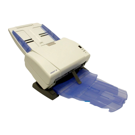
- Page 167 NSIGHT 20 Scanners You’ve just purchased a Scantron iNSIGHT 20 OMR and image scanner. For over 30 years, Scantron scanners have offered accurate and reliable data capture through both Optical Mark Recognition (OMR) and image scanning. The iNSIGHT 20 from Scantron is a compact, affordable desktop model scanner that combines document imaging technology along with the proven data collection capabilities and accuracy of optical mark recognition (OMR).