Table of Contents
Advertisement
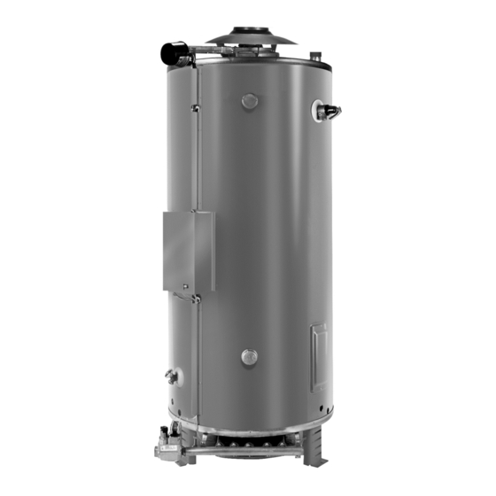
Service Handbook
COMMERCIAL GAS HIGH EFFICIENCY WATER HEATERS
FOR MODELS:
SBD71120(N,P) through SBD100390(N,P)E
Series 118 & 119
300 Maddox Simpson Parkway
INSTALLATION CONSIDERATIONS - PRE SERVICE CHECKS -
Lebanon, TN 37090
CONSTRUCTION - OPERATION & SERVICE - TROUBLESHOOTING
SERVICING SHOULD ONLY BE PERFORMED BY A QUALIFIED SERVICE TECHNICIAN
PRINTED IN THE U.S.A. 1016
100278164_2000536778
Advertisement
Table of Contents
Troubleshooting

Subscribe to Our Youtube Channel
Related Manuals for State Water Heaters SBD71120


Summary of Contents for State Water Heaters SBD71120
- Page 1 Service Handbook COMMERCIAL GAS HIGH EFFICIENCY WATER HEATERS FOR MODELS: SBD71120(N,P) through SBD100390(N,P)E Series 118 & 119 300 Maddox Simpson Parkway INSTALLATION CONSIDERATIONS - PRE SERVICE CHECKS - Lebanon, TN 37090 CONSTRUCTION - OPERATION & SERVICE - TROUBLESHOOTING SERVICING SHOULD ONLY BE PERFORMED BY A QUALIFIED SERVICE TECHNICIAN PRINTED IN THE U.S.A.
-
Page 2: Table Of Contents
TABLE OF CONTENTS INTRODUCTION ..................2 Qualifications ................. 2 Service Warning ................2 Service Reminder ................2 Tools Recommended ..............2 INSTALLATION CONSIDERATIONS ............3 Instruction Manual ................. 3 Closed Water Systems ..............3 Thermal Expansion ............... 3 Air Requirements ................3 Contaminated Air ................ -
Page 3: Introduction
INTRODUCTION This Service Handbook covers the water heater Model and Series numbers listed on the front cover only. The instructions and illustrations contained in this service handbook will provide you with troubleshooting procedures to verify proper operation and diagnose and repair common service problems. QUALIFICATIONS QUALIFIED INSTALLER OR SERVICE AGENCY Installation and service of this water heater requires ability equivalent to that of a Qualified Agency (as defined... -
Page 4: Installation Considerations
INSTALLATION CONSIDERATIONS This section of the Service Handbook covers some of the critical installation requirements that, when overlooked, often result in operational problems, down time and needless parts replacement. Costs to correct installation errors are not covered under the limited warranty. Ensure all installation requirements and instructions contained in the Instruction Manual that came with the water heater have been followed prior to performing any service procedures. -
Page 5: Venting
VENTING This section of the Service Handbook is not a complete venting installation instruction. Refer to the Instruction Manual that came with the water heater; ensure the venting has been installed per all Instruction Manual requirements. Costs to correct installation errors are not covered under the limited warranty. The instructions in this section on venting must be followed to avoid choked combustion or recirculation of flue gases. -
Page 6: Power Vent Kits For Sidewall Venting
POWER VENT KITS FOR SIDEWALL VENTING SBD model water heaters can be used with power vent kits for sidewall venting. State Water Heaters offers power vent kits for use on installations with a maximum of 100 equivalent feet of vent piping. The power vent kits also use type B vent materials. -
Page 7: Gas Supply Systems
GAS SUPPLY SYSTEMS Low pressure building gas supply systems are defined as those systems that cannot under any circumstances exceed 14” W.C. (1/2 PSI Gauge). These systems do not require pressure regulation. Measurements should be taken to insure that gas pressures are stable and fall within the requirements stated on the water heater rating plate. -
Page 8: Gas Piping
GAS PIPING Contact your local gas service company to ensure that adequate gas service is available and to review applicable installation codes for your area. Size the main gas line in accordance with Table below. The figures shown are for straight lengths of pipe at 0.5 in. - Page 9 To trap any dirt or foreign material in the gas supply line, a sediment trap must be incorporated in the piping (see Figure below). The sediment trap must be readily accessible and not subject to freezing conditions. Install in accordance with recommendations of serving gas suppliers. Refer to the latest version of the National Fuel Gas Code.
-
Page 10: Features And Components
FEATURES AND COMPONENTS THE HYDROCANNON (SELF-CLEANING SYSTEM) These units include The Hydrocannon (Self-Cleaning System) installed in the front water inlet. The Hydrocannon inlet tube can only be used in the front water inlet connection. Do not install the Hydrocannon inlet tube in either the top or back inlet water connection. The Hydrocannon must be oriented correctly for proper function. -
Page 11: Gas Control Valve
GAS CONTROL VALVE For Natural Gas For Propane (LP) • Inlet screen helps protect from debris. • Tamper resistant screws. • Conveniently located ON/OFF switch. • Inlet and Outlet pressure taps. • Adjustable gas regulator. Note: ON/OFF switch must be in the ON position to perform ohm/continuity tests. ON/OFF switch replaced the gas cock on this new valve design. -
Page 12: White Rodgers Integrated Temperature Control Switch
WHITE RODGERS INTEGRATED TEMPERATURE CONTROL SWITCH The digital thermostat contains the high limit (energy cutout) switch. The high limit switch interrupts main burner gas flow should the water temperature reach 203°F (95°C). In the event of high limit switch operation, the water heater cannot be restarted unless the water temperature is reduced to approximately 120°F (49°C). -
Page 13: Electronic Ignition Control/ Ignition Module
ELECTRONIC IGNITION CONTROL/ IGNITION MODULE Each heater is equipped with a Honeywell ignition module. The solid state ignition control ignites the pilot burner gas by creating a spark at the pilot assembly. Pilot gas is ignited and burns during each running cycle. The main burner and pilot gases are cut off during the OFF cycle. -
Page 14: Sequence Of Operation Flow Chart
SEQUENCE OF OPERATION FLOW CHART Servicing should only be performed by a Qualified Service Technician... -
Page 15: Troubleshooting Checklist
TROUBLESHOOTING CHECKLIST REMEDY COMPLAINT CAUSE USER QUALIFIED SERVICE AGENCY Set thermostat dial to a higher Thermostat set too low. temperature. Check continuity and resistance Water not hot enough. Upper and/or lower temperature (Ohms) of upper and lower Call qualified service agency. probe out of calibration. -
Page 16: General Service Chart
GENERAL SERVICE CHART Condition Cause Solution DAMPER OPENS NO POWER • DAMPER NOT FULLY OPEN • REPLACE DAMPER. • DEFECTIVE PROTECTOR • REPLACE PC BOARD. TO IID MODULE SWITCH PILOT LIGHTS, SPARKS PILOT FLAME NOT PROVING SEE FLAME RECTIFICATION - STEP CONTINUOUSLY HEATER WILL NOT IGNITE PROVING... -
Page 17: Fault And Warning Codes
FAULT AND WARNING CODES STEP 1. TROUBLESHOOTING THE WATER HEATERS CHECK/REPAIR: • Check that 120 VAC is supplied to the heater. • Make sure the tank is full of water. • Make sure the gas is supplied to the unit. EFFIKAL DAMPER The wiring colors from the damper PC Board are different colors than the wires on the heater wiring harness. -
Page 18: Flue Damper
HARNESS CHART Heater Harness Function Damper Harness Black 24V Hot 1 - Brown Yellow 24V from Thermostat 2 - Orange 24V from Damper 3 - Yellow White 24V Common 4 - Black CONDITION: • Damper closed. • High Limit closed. FLUE DAMPER Do not turn damper open manually or motor damage will result, use the service switch. -
Page 19: Effikal Rvgp-Ksf-Series Flue Damper Troubleshooting Guide
See figure on front page of this insert sheet IMPORTANT: DAMPER MUST BE OPEN BEFORE COMBUSTION TAKES PLACE. If all steps have been tried and damper problems persists, contact State Water Heaters (800) 365-8170. Servicing should only be performed by a Qualified Service Technician... -
Page 20: Step 2: Test For 24Vac Between Black And Orange On Damper Pc Board
STEP 2: TEST FOR 24VAC BETWEEN BLACK AND ORANGE ON DAMPER PC BOARD THEN 24VAC is present - damper NOT opening • Check Service Switch Position. Replace Damper Assembly. 24VAC is not present. • Check Wiring Harness to Thermostat. 24VAC present - Damper Opens •... -
Page 21: Symptoms For A Blown Fuse
Visually inspect the fuse to see if it is blown, the inside of the fuse can appear dark, discolored and burnt. The link also will be broken inside. SYMPTOMS FOR A BLOWN FUSE • Power, Call for heat, Reset Status and ECO Status lights are not visible on the thermostat. •... -
Page 22: Step 4: Test For 24Vac Between Black And Yellow On Damper Pc Board
STEP 4: TEST FOR 24VAC BETWEEN BLACK AND YELLOW ON DAMPER PC BOARD THEN 24VAC is present • This is correct - Continue to Step 5. 24VAC is not present. • Check Service Switch position. • Check the harness plug connections. •... -
Page 23: Step 6: Iid Module Test (Power To The Pilot Valve)
STEP 6: IID MODULE TEST (POWER TO THE PILOT VALVE) CONDITION: • 24VAC to module, no pilot. Using a multimeter, test for 24 VAC between terminal PV and 24 V (GND) on the IID during the 90 second trial for ignition. THEN The meter does not read 24 VAC and the IID module •... -
Page 24: Step 7: Pilot Spark Test
STEP 7: PILOT SPARK TEST CONDITION: • 24VAC at PV, no pilot. Visually/audibly check for spark at the pilot assembly. Note: The pilot burner mounts on the left side of the main burner. THEN The igniter is not sparking during the 90 second trial Check for: for ignition. -
Page 25: Step 8: Flame Rectification
STEP 8: FLAME RECTIFICATION CONDITION: • Pilot Flame Noted, Pilot Sparking Continues, No Main Burner. Note: Flame rectification means that an alternating current (AC) signal is changed to a direct current (DC) signal. The pilot flame is the 'switch' which connects the pilot hood to the igniter and ground. If the pilot hood and igniter sensor had the same surface area, the flame 'switch' would conduct an AC signal. -
Page 26: Step 9: Iid Module Test
STEP 9: IID MODULE TEST CONDITION: • Pilot Flame Noted, No Sparking, No Main Burner. Using a multimeter, test for 24 VAC between terminal MV on the IID and 24V (GND). THEN 24 VAC is not present: • Replace the IID module. Check the gas valve before applying power to replacement module. -
Page 27: Step 10: Main Burner Test
STEP 10: MAIN BURNER TEST CONDITION: • Pilot flame Noted, Main burner Check. Visually check for main burner. THEN The main burner ignites: • Sequence is complete. The main burner does not ignite. • Check gas supply. • Check gas control valve operation before replacing. Servicing should only be performed by a Qualified Service Technician... -
Page 28: Wiring Diagram - 118/119 Series Controls
WIRING DIAGRAM - 118/119 SERIES CONTROLS Servicing should only be performed by a Qualified Service Technician... - Page 29 NOTES Servicing should only be performed by a Qualified Service Technician...
- Page 30 NOTES Servicing should only be performed by a Qualified Service Technician...
- Page 31 COMMERCIAL GAS WATER HEATERS For additional information contact: State Water Heaters 500 Tennessee Waltz Parkway, Ashland City, TN 37015 Technical Support: 800-365-8170 • Parts: 800-821-2017 www.statewaterheaters.com Copyright © 2016, State Industries, Inc. All rights reserved.
Need help?
Do you have a question about the SBD71120 and is the answer not in the manual?
Questions and answers