Table of Contents
Advertisement
Service
Information
© 2011 Reg. Office: Peterborough PE2 9JB Registered in London: 106725
Indesit Company UK Ltd
5407399 Issue 2 March 2011
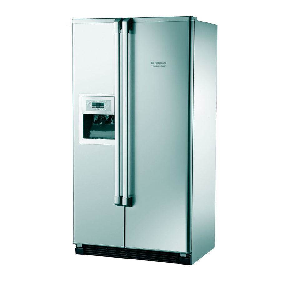
HOTPOINT
SIDE-BY-SIDE
FRIDGE
FREEZERS
(7 ~ Segment Version)
Models
Covered
Energy Band 'A' Models
MSZ801DF
MSZ802DF
MSZ803DF
MSZ806DF
Comm.
Code
48862
46196
48863
57217
Advertisement
Table of Contents

Subscribe to Our Youtube Channel
Related Manuals for Hotpoint MSZ802DF


Summary of Contents for Hotpoint MSZ802DF
- Page 1 SIDE-BY-SIDE FRIDGE FREEZERS (7 ~ Segment Version) Models Comm. Covered Code Energy Band 'A' Models MSZ801DF 48862 MSZ802DF 46196 MSZ803DF 48863 MSZ806DF 57217 Service Information Indesit Company UK Ltd © 2011 Reg. Office: Peterborough PE2 9JB Registered in London: 106725...
-
Page 2: Health & Safety
Indesit Company HEALTH AND SAFETY For the servicing of refrigeration products, containing R134a refrigerant. These instructions are in addition to any other Company procedures already published. Published primarily for Indesit Company engineers working in the UK or Southern Ireland, for which these instructions are MANDATORY. -
Page 3: Table Of Contents
Indesit Company CONTENTS Health & Safety ............2 Index &... -
Page 4: Introduction
July 2007. All models are similar with regard to the furniture design, but there are variations for exterior colour. Models MSZ801DF, MSZ802DF, MSZ803DF and MSZ806DF interior: The interior of the fridge has safety glass shelves, one meat drawer (chiller) and one humidity controlled salad bin (crisper) with a glass cover. -
Page 5: Specifications
Indesit Company SPECIFICATIONS Introduction Date Colours June 2007 July 2007 July 2008 Polar White MSZ801DF Silver MSZ802DF Stainless Steel MSZ803DF Black MSZ806DF Suffix 'DF' = dispenser models GENERAL: Manufactured in: Italy Appliance Type: Side by Side Static / No- Frost: No-Frost Door Hinging - Freezer L/H &... - Page 6 Indesit Company TECHNICAL DATA: Power Supply Voltage: 220/240 V Power Supply Frequency: 50 Hz Mains Water Supply: Min. 1.7 bar Max. 8.1 bar Freezer Lamp: E27 40W 220V - 240V Dispenser Lamp: E14 10W 230 - 240V Fridge Lamp (Blue Light): T-Click 40W 220V - 240V ENERGY Energy Class:...
-
Page 7: Appliance Dimensions & Water Filter
Indesit Company APPLIANCE DIMENSIONS (all measurements are approximate) APERTURE MEASUREMENTS PLAN VIEW (WITH DOORS OPEN 90° AND FULLY) Cabinet Height = 1760 mm Cabinet Height with doors = 1765 mm Depth including door handles: 605 mm + 150 mm = 750 mm Depth without doors = 605 mm Depth without handles: 605 mm + 110 mm = 715 mm WATER FILTER... -
Page 8: Detailed View
Indesit Company DETAILED VIEW REFRIGERATOR COMPARTMENT FREEZER COMPARTMENT A. Inside light N. Automatic ice-maker B* . Inside light (not fitted) O. Glass shelves / Racks (depending on the model) C. Adjustable shelf P. Drawer / Bottom basket (depending on the model) D. -
Page 9: Control Panel Interface
Indesit Company CONTROL PANEL INTERFACE TEMPERATURE CONTROL PANEL BUTTON DESCRIPTION FUNCTION Freezer ~ This function allows you to adjust the displayed temperature. temperature To adjust the temperature press the relevant + / - button until the adjust / select required freezer temperature is displayed on the left. Super freeze ~ This function activates the super freeze (fast freeze) so fresh food can be frozen. -
Page 10: Control Panel Interface
Indesit Company CONTROL PANEL INTERFACE ICE & DISPENSER CONTROL PANEL BUTTON DESCRIPTION FUNCTION Dispenser light ~ This function switches on the dispenser light. To enable / disable press the button. Stand-by function ~ This function turns off the ice maker. To enable the ice maker press and hold until the ice or crushed ice symbol is displayed. -
Page 11: Description Of Functions
Indesit Company DESCRIPTION OF FUNCTIONS Super freeze function ~ This enables and controls the compressor, condenser fan and evaporator fan to cool down the freezer compartment independently of the temperature settings set by the user. The super freeze function will end automatically after 48 hours after activation. -
Page 12: Component Functions
Indesit Company COMPONENT FUNCTIONS General Information The power module is made up of a number of smaller individual modules (sections), each one controlling a functional component. The modules are linked together when required to control a particular function or functions. The linking of the individual modules is optional and therefore allows for each module to be switched ON or OFF, this is determined from the data stored or collected by the modules and the results of module comparisons. - Page 13 Indesit Company COMPONENT FUNCTIONS Compressor The compressor is managed by the power module and switches on whenever a demand for cooling is received. There are situations of cooling demand in which the compressor remains off. These are as follows: Compressor protection: the compressor switches on once a minimum safety time lag has elapsed since the last power-off, thereby allowing the refrigerant gas pressure to reach a point of equilibrium in the refrigerant circuit.
-
Page 14: Temperature Tables
Indesit Company TEMPERATURE TABLES ON - OFF DAMPER TEMPERATURE TABLE REFRIGERATOR Temperature Sensor Refrigerator Display Damper (Baffle) ON (°C) Damper (Baffle) OFF (°C) Super Cool Any of the above FREEZER CONTROL TABLE FREEZER Temperature Sensor Freezer Display Compressor ON (°C) Compressor OFF (°C) -21.5 -23.5... -
Page 15: Alarm Conditions
Indesit Company ALARM CONDITIONS Control Panel Interface (mounted above dispenser assembly) Example above shows the ALARM 'd' flashing in the fridge temperature display. • Check fridge Air Baffle (Damper) / Connections. TEMPERATURE DISPLAY ALARM CONDITION Freezer Fridge Check freezer sensor / connections. Freezer too warm usually shown when turned on for the first time *. -
Page 16: Auto-Test And Fault Conditions
(2.5 minutes) completes its Manually: Baffle/damper triac Q3, MSZ801DF set-up and returns (cc48862) to normal MSZ802DF Switching OFF the operation. Sequence Code 09: (3 seconds) (cc46196) power supply to Water Valve (Ice Maker), the appliance. MSZ803DF STEP 3: Open the (cc48863) freezer door. - Page 17 Indesit Company Control Panel Interface (mounted above dispenser assembly) Example above shows Sequence '07' of the Auto Test in the freezer temperature display and fault code '7' to '0' flashing alternatively in the fridge temperature display. • Check evaporator heater / connections. Fault conditions: are signalled to the engineer during Auto Test.
-
Page 18: Air Flow
Indesit Company AIR FLOW COMPRESSOR AND CONDENSER COMPARTMENT The condenser fan is mounted at the rear near the compressor and draws air from the room through the right side of the front lower grille (A), through the condenser (B), around the compressor (C) where it exits out of the rear panel (D) but mainly passes over the dissipator to evaporate the defrost water (E) and finally exits out through the left side of the front lower grille. - Page 19 Indesit Company AIR FLOW FRIDGE AND FREEZER INTERIOR COMPARTMENTS FREEZER The freezer evaporator is mounted just above the evaporator assembly (F). The fan draws air up through the evaporator where it is cooled (G) and blows into the top duct panel where it is channelled out through outlet ports (H).
-
Page 20: Ice-Maker Function And Adjustment
Indesit Company THE SANKYO ICEMAKER HOW THE ICEMAKER WORKS • Water is automatically measured into the icemaker mould by the inlet solenoid water valve. • The Bi-metal thermostat mounted between the support housing and the mould detects the water / ice temperature. -
Page 21: Power Module Parameters
Indesit Company POWER MODULE Parameters Parameters set in the module memory control the appliance functions. The minimum and maximum values for temperature are preset in the module memory. Sensors monitor temperature and the values are registered in the module. Where the sensor values are outside the presets a Parameter Values particular function will start or stop. -
Page 22: Power Module Parameters
Indesit Company POWER MODULE Parameters DEFROST HEATING ELEMENTS • Compressor ON time since the last defrost cycle. 8 hours, but the start time will reduce dependant on door opening times. Defrost Heating Elements - • The appliance is plugged in and switched on. The parameters utilised to start the defrost cycle are as follows: •... -
Page 23: Servicing & Dismantling Instructions
Indesit Company SERVICING & DISMANTLING INSTRUCTIONS Before commencing any work refer to the Safety Notes at the beginning of this manual. All necessary precautions must be taken to prevent damage to the premises and the appliance. The appliance must be disconnected from the mains electricity supply. Where necessary, food and containers should be removed and stored according to the customer’s requirements. - Page 24 Indesit Company G. FREEZER LAMP COVER & LAMP Squeeze the sides inward and down. The front location tab can then be unhooked from its slot. The lamp has two spade terminations and can be pulled out. H. FREEZER REAR PANELS (EVAPORATOR COVERS) Remove the icemaker as in E and its support cradle.
- Page 25 Indesit Company M. DEFROST HEATER (See K for testing purposes) Remove the components as in E, F, G and H. Disconnect the two connections to the heater. Remove the components as in K. Push the heater upward out of its retaining clips, the clips can now be removed completely and the heater withdrawn from the evaporator.
- Page 26 Indesit Company U. POWER MODULE Remove the cover as in P. Remove the 2 screws securing the module and cover to the rear right hand edge of the cabinet. Prise the cover from the module box to gain access. V. FRIDGE DAMPER (BAFFLE) WORKING FROM THE FREEZER COMPARTMENT Remove the ice bucket.
-
Page 27: Compressor Connection Chart
Indesit Company COMPRESSOR CONNECTION CHART EMBRACO COMPRESSOR TERMINAL BLOCK 1 ~ COMMON (Overload) L ~ LIVE (line) & Capacitor ~ EARTH S ~ CAPACITOR N ~ NEUTRAL SCHEMATIC VIEW OF TERMINAL BLOCK TERMINAL COLOUR DESCRIPTION BLACK COMMON (OVERLOAD) BROWN LIVE & RUN CAPACITOR GREEN/YELLOW EARTH BLUE... -
Page 28: Power Module Edge Connections
POWER MODULE EDGE CONNECTIONS SOME TERMINALS MAY NOT BE USED, DEPENDING ON THE MODEL Pin 9 ( water valve feedback ) Pin 10 ( DC Fan optional ) Pin 9 ( Ice maker + ) Pin 10 ( NC ) Pin 12 ( Freezer door communication RX ) Pin 8 ( Ice maker - ) Pin 11 ( Emitter IDI load ) -
Page 29: Connector Block Chart
Indesit Company CONNECTOR BLOCK CHART DISPENSER ASSEMBLY CONTROL PANEL MODULE MICRO SWITCHES ICE DISPENSER WATER DISPENSER HEATER SWITCH 6-PIN CONNECTOR LAMP HOLDER EVAPORATOR FAN FREEZER DOOR FRIDGE COMPARTMENT & CUT-OUT TOP HINGE 6-PIN CONNECTOR DAMPER Service Manual UK English 29 of 37... -
Page 30: Theoretical Wiring Diagram
THEORETICAL WIRING DIAGRAM... -
Page 31: Thermistor Sensor Location
Indesit Company THERMISTOR (NTC) SENSOR LOCATION Two sensors are used in these models, the approximate position is as follows: - 1. Freezer Air Sensor - Located in the left liner wall just below the icemaker. 2. Fridge Air Sensor - Located in the centre of the rear liner wall of the fridge. Temperature Accuracy Temperature... -
Page 32: Installation Instructions
Indesit Company INSTALLATION INSTRUCTIONS INTRODUCTION The model you are installing may differ slightly with respect to some descriptions in this installation, since this covers several models. Install the appliance in a dry and well-ventilated place. Avoid locations in direct sunlight or near a source of heat (oven, heating, etc.). If this cannot be avoided, install the appliance respecting the following minimum distances: Coal or paraffin stoves: 300 mm Electric and/or gas stoves: 30 mm... -
Page 33: Service Manual Uk
Indesit Company INSTALLATION INSTRUCTIONS LEVELLING THE APPLIANCE The refrigerator has two front and two rear wheels at the base of the product on each side that can be adjusted (see Figure A), or four wheels of which only the two front wheels can be adjusted (see Figure B). -
Page 34: Service Manual Uk
Indesit Company INSTALLATION INSTRUCTIONS REMOVING THE FREEZER DOOR (A) REMOVING THE REFRIGERATOR DOOR (B) Service Manual UK English 34 of 37... -
Page 35: Service Manual Uk
Indesit Company INSTALLATION INSTRUCTIONS MOUNTING THE FREEZER DOOR (C) MOUNTING THE REFRIGERATOR DOOR (D) Service Manual UK English 35 of 37... - Page 36 Indesit Company INSTALLATION INSTRUCTIONS HORIZONTAL ALIGNMENT OF FREEZER AND REFRIGERATOR DOORS (E) VERTICAL ALIGNMENT OF FREEZER AND REFRIGERATOR DOORS (F) Service Manual UK English 36 of 37...
-
Page 37: Service Manual Uk
Indesit Company Service Manual UK English 37 of 37...
Need help?
Do you have a question about the MSZ802DF and is the answer not in the manual?
Questions and answers