Table of Contents
Advertisement
Quick Links
Field Intelligent Device – Premium Value Series
Electromagnetic Flowmeter
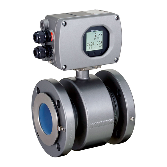
Introduction
The electromagnetic flowmeter uses Faraday's Law of
electromagnetic induction to measure the process flow.
The device consists of two units: a detector, through
which the fluid to be measured flows and in which
low-level signals proportional to flow rates are
obtained; and a converter, which supplies excitation
current to the detector, and amplifies the signals from
the detector and then processes and converts the signals
into the 4–20mAdc current signal or communication
signal. Combined with a multi-functional converter
LF620 (combined type) or LF622 (separate type)
equipped with its original patented noise-suppression
circuit and advanced algorithms. The GF630 has a very
high tolerance to noise, giving the unit a very stable
output even for slurry fluid measurement. IR (Infrared)
switches enable the parameter setting of the converter
without removing the cover. Flow direction can be set
in either way, and its unique 128 x 128 dot matrix LCD
display allows the LCD to be rotated electronically to
90, 180 and 270 degrees without opening the cover.
The terminal block in LCD side make easy to wire in
case of the combined type.
The AF900 hand-held terminal (HART*
communicator) can be used to communicate with the
flowmeter from a remote place. PROFIBUS-PA*
3
Modbus*
interface is available as an option.
*1:
HART protocol (Highway Addressable Remote Transducer) is a communication
protocol for industrial sensors recommended by the HCF (HARTCommunication
Foundation).
*2: PROFIBUS is the communication protocol for factory and process automation that
the PROFIBUS Organization recommends. Instead of analog control with a
conventional analog signal (4-20mA), it is fieldbus which digitizes all signals.
Flowmeters support PROFIBUS-PA.
*3:Modbus is the communication protocol that Modicon Inc. developed. Physical
layer is RS485.
Combined type
Combined type
Combined type
Combined type
GF630/LF620
GF630/LF620
GF630/LF620
GF630/LF620
GF630/LF620F
GF630/LF620F
GF630/LF620F
GF630/LF620F
Figure 1. Configuration
1 1 1 1
1
2
or
Separate type
Separate
type
Separate
Separate
type
type
GF632/LF622
GF632/LF622
GF632/LF622
GF632/LF622
GF632/LF622F
GF632/LF622F
GF632/LF622F
GF632/LF622F
15 to 600 mm (1/2" to 24")
GF630/LF620
GF630/LF620
GF630/LF620
GF630/LF620
GF630/LF600
GF630/LF620F
GF630/LF620F
GF630/LF620F
GF630/LF620F
Figure2. GF630 Premium Value series
Figure2.
Figure2.
Figure2.
GF630 Premium Value series
GF630 Premium Value series
GF630 Premium Value series
Flowmeters
Flow
Flow
Flow
Certification
number
Z01207
Specifications
Overall Specifications
Measurement range in terms of flow velocity:
0 – 0.3 m/s to 0 –10 m/s (0 –1.0 ft/s to 0 – 32.8 ft/s).
0 – 0.1 m/s to 0 – 0.3 m/s (0 – 0.3 ft/s to 0 – 1.0 ft/s)
range is available optionally for meter size 1/2" to
18" (15 to 450 mm).
Accuracy:
< 1/2" to 18" (15 mm to 450 mm) >
± ± ± ± 0.2 % of Rate
*1.
* This pulse output error result is established under standard
operating conditions at Toshiba's admitted flow calibration
facility.
* Individual meter measurement error may vary up to ±0.5% of
Rate at 1.64 ft/s (0.5m/s) or more. Or it may vary up to ±0.3%
of rate ±0.039 inch/s (1mm/s) at 1.64 ft/s (0.5m/s) or less.
* Current output: plus ± 8µA (0.05% of span).
* Refer to individual calibration data for each individual meter's
measurement error.
GF630 /LF620
GF632 /LF622
LF622
LF622
LF622
LF622
GF632
GF632
GF632
LF602
GF632
GF632
LF622F
LF622F
LF622F
LF622F
meters
meters
meters
Certification
No. PM09896
For PU lined flowmeter
EJL- - - - 140
EJL
140D D D D
EJL
EJL
140
140
Advertisement
Table of Contents

Related Manuals for Toshiba GF630


Summary of Contents for Toshiba GF630
-
Page 1: Specifications
LF622F LF622F LF622F LF622F LF620 (combined type) or LF622 (separate type) equipped with its original patented noise-suppression circuit and advanced algorithms. The GF630 has a very Figure2. Figure2. Figure2. Figure2. GF630 Premium Value series GF630 Premium Value series GF630 Premium Value series... - Page 2 EN 1092-1 PN 16 :15 to 600mm (1/2” to 24”) This pulse output error result is established under standard Principal materials: operating conditions at Toshiba's flow calibration facility, Case — carbon steel Fuchu Japan. Individual meter measurement error may vary up to ±0.5% of Flange material —...
- Page 3 GF630/LF620 GF632/LF622 DO1 and DO2 functions — One of the following Model LF620 and LF622 converters functions can be assigned to DO1 and/or DO2. Input signals • Pulse output (available only for DO1,DO2) Analog signal — the voltage signal from detector,...
- Page 4 GF630/LF620 GF632/LF622 Communications output : : : : Zero and span calibration: • HART (std.) Built-in calibration signal source allows converter Digital signal is superimposed on 4–20mAdc unit check. current signal as follows: Conditions when power fails: Conforms to HART protocol Parameter setting values are stored in Load resistance: 240 to 750Ω...
- Page 5 GF630/LF620 GF632/LF622 Vibration resistance: No resonance to the following levels of vibration: • 10 to 150Hz with acceleration of 9.8m/s • Vibration of 30Hz with 29.4 m/s in 4h in each direction will not cause any defect to unit. Note: Avoid using the flowmeter in an environment with constant vibration.
-
Page 6: Installation
Figure Figure 3 3 3 3 . GF63 Figure Figure . GF63 . GF630/LF620 and GF630/LF620F combined type flowmeters . GF63 0/LF620 and GF630/LF620F combined type flowmeters 0/LF620 and GF630/LF620F combined type flowmeters 0/LF620 and GF630/LF620F combined type flowmeters Meter sizes 15 Meter sizes 15mm mm (1/2") t... - Page 7 GF630/LF620 GF632/LF622 Separate type GF632/LF622 and GF632/LF622F 36 (1.42) φ98 (φ3.86) Note1: Eye bolts are provided at the flange Note2 for flowmeters sized 200mm (8") or above. Note1 Note2: Cable glands are not provided for GF632/LF622F cFMus approved type. Refer to the part Cable connection port at detector.
- Page 8 Digital input (20~30Vdc) or Modbus the connector joints. Digital output 2 Signal common for DI and DO Digital output 1 Grounding with 100Ω or less Power cable I/O cable ground resistance Figure 6. Combined type GF630/LF620 and GF630/LF620F flowmeters Wiring Diagram...
-
Page 9: Profibus-Pa
GF630/LF620 GF632/LF622 ・ ・ ・ ・ Separate type GF632/LF622 and GF632/LF622F flowmeter Instrument panel : Ordered separately Ⅳ wire 5.5mm Grounding with 100Ω or less or more ground resistance Grounding with 100Ω or less Power switch ground resistance (External double-pole power switch) - Page 10 GF630/LF620 GF632/LF622 (7) Only one PROFIBUS-PA cable goes through a Wiring Precautions cable gland of the Electromagnetic Flowmeter. (1) Explosion proof type flowmeters are not Use the junction box at system configuration provided cable glands. (8) Install a terminator to flowmeter that connected Refer to the part Cable connection port at to end of Modbus network.
- Page 11 GF630/LF620 GF632/LF622 Table Table Table Table 2 2 2 2 ..Flow Rate and Flow velocity Flow Rate and Flow velocity Flow Rate and Flow velocity Flow Rate and Flow velocity ( ( ( (SI SI SI SI u u u unit)
- Page 12 GF630/LF620 GF632/LF622 Piping Precautions About establishment environment (1) Design piping so that the flowmeter detector pipe is Do not store or install the flowmeter : always filled with the fluid being measured, • Where there is direct sunlight. whether the fluid is flowing or not.
-
Page 13: Ordering Information
Ordering Grounding rings Ordering Information When you purchase the grounding ring, refer to 1. When ordering the GF630 series flowmeters, refer Table 5. to Tables 6 to 8 (Type Specification Codes). An entry must be made for each of the columns in Table 5. -
Page 14: Meter Sizes
GF630/LF620 GF632/LF622 (Number of tabs) ΦD2 ΦD1 ASME B 16.5 class 150 Meter size JIS B 2220 10K (Unit: mm) EN 1092-1 PN10 and PN16 (Unit: mm) (Unit: inch) ΦD1 ΦD2 inch ΦD1 ΦD2 ΦD1 ΦD2 PN10 PN16 PN10 PN16 0.16... - Page 15 GF630/LF620 GF632/LF622 Table Table 6 6 6 6 ..Specification Code Specification Code ( ( ( ( Flange type detector GF630 (Comb Flange type detector GF630 (Combined type) ined type) ) ) ) ) Table Table Specification Code...
- Page 16 GF630/LF620 GF632/LF622 Table Table 7 7 7 7 ..Specification Code Specification Code ( ( ( ( Flange type detector GF632 (Separate type) Flange type detector GF632 (Separate type) ) ) ) ) Table Table Specification Code...
- Page 17 GF630/LF620 GF632/LF622 Table Table Table Table 8 8 8 8 . Specification Code . Specification Code . Specification Code . Specification Code for LF620/LF622 converters for LF620/LF622 converters for LF620/LF622 converters for LF620/LF622 converters Model Specification Code Contents LF620 LF622...
- Page 18 Specifications are subject to change without notice. Printed in Japan 2011-5 (TDOC) Misuse of this product can result in damages to property or human injury. © TOSHIBA Corporation 2011 Read related manuals carefully before using this product. All Rights Reserved.