Table of Contents
Advertisement
Quick Links
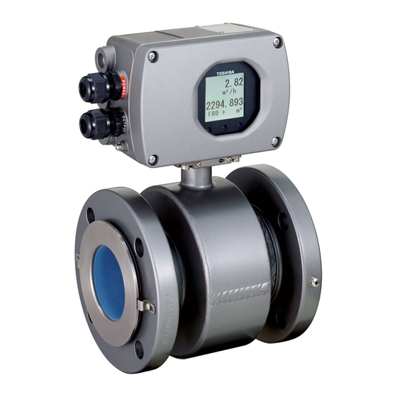
ELECTROMAGNETIC FLOWMETER DETECTOR
NOTES
Before using the equipment, please read this manual carefully and understand the
contents, and then use the equipment correctly.
• NEVER attempt to operate the equipment in any ways that are not described in this
instruction manual.
• After reading this manual, store it with care in a place where it can be referred to
whenever needed.
• Please be sure that this manual is delivered to the personnel who will use this product.
MODEL GF630, GF632
INSTRUCTION MANUAL
6F8A0882
© TOSHIBA Corporation 2010
All Rights Reserved.
Advertisement
Table of Contents
Troubleshooting

Related Manuals for Toshiba GF630


Summary of Contents for Toshiba GF630
- Page 1 6F8A0882 ELECTROMAGNETIC FLOWMETER DETECTOR MODEL GF630, GF632 INSTRUCTION MANUAL © TOSHIBA Corporation 2010 All Rights Reserved. NOTES Before using the equipment, please read this manual carefully and understand the contents, and then use the equipment correctly.
- Page 2 6F8A0882 NOTICE We thank you very much for your purchase of our GF630 series electromagnetic flowmeter detector. Integral type GF630/LF600,LF610 and LF620 Separate type detector GF632 This instruction manual describes the notes on using an electromagnetic flowmeter detector, installation, configuration and maintenance.
-
Page 3: Safety Precautions
6F8A0882 SAFETY PRECAUTIONS Safety signs and labels affixed to the product and/or described in this manual give important information for using the product safely. They help prevent damage to property and obviate hazards for persons using the product. Make yourself familiar with signal words and symbols used for safety signs and labels. - Page 4 SAFETY PRECAUTIONS(continued) Safety Precautions for Installation and Wiring WARNING Do not use the GF630/LF600,LF610,LF620 and GF632 in an explosive atmosphere. Using this product except for the FM Approval type in an explosive atmosphere can cause explosion DON’T ...
- Page 5 Warranty and Limitation of Liability Toshiba does not accept liability for any damage or loss, material or personal, caused as a direct or indirect result of the operation of this product in connection with, or due to, the occurrence of any event of force majeure (including fire or earthquake) or the misuse of this product, whether intentional or accidental.
-
Page 6: Handling Precautions
6F8A0882 Handling Precautions To obtain the optimum performance from the GF630/LF600,LF610,LF620 and GF632 for years of continuous operation, observe the following precautions. (1) Do not store or install the flowmeter in: • places where there is direct sunlight. If this is unavoidable, use an appropriate sunshade. - Page 7 6F8A0882 Handling Precautions (continued) (9) Since a varistor is built in converter, do not conduct a withstand voltage test for the converter. In addition, the voltage for checking the insulation of the converter must be 250VDC or lower.
-
Page 8: Table Of Contents
6F8A0882 Table of Contents SAFETY PRECAUTIONS ····················································································· 2 Handling Precautions ······························································································ 5 1. Product Inspection and Storage ······································································ 8 1.1 Product Inspection ······················································································· 8 1.2 Storage ········································································································ 8 2. Overview ············································································································ 9 3. Names of Parts ································································································· 10 4. -
Page 9: Product Inspection And Storage
Make sure the type and specifications of the flowmeter are in accordance with the ordered specifications. If you cannot find the items listed above or any problem exists, contact your nearest Toshiba representative. 1.2 Strage To store the electromagnetic flowmeter after opening the package, select a storing place as follows... -
Page 10: Overview
Faraday's Law of electromagnetic induction. The device consists of two units: the GF630 and GF632 detector, through which the fluid to be measured flows, and the converter, which receives the electromotive force signals from the detector, then converts the signals into the 4–20 mA dc signal. -
Page 11: Names Of Parts
( Provided for PTFE lining only ) GF630 Detector Figure 3.1.1 Appearance of GF630/LF600 and LF610 Note: The ground cables are included in the package, so install them to flanges as shown in the Fig.4.5 as needed. (The screws are equipped to detector flanges.) - Page 12 GF630 Detector Figure 3.1.2 Appearance of GF630/LF620 Note: The ground cables are included in the package, so install them to flanges as shown in the Fig.4.5 as needed. (The screws are equipped to detector flanges.) ...
- Page 13 6F8A0882 3.1.3 Appearance of Detector GF632 Separate for Signal cable for Excitation cable Terminal Box Cover Terminal Box Flow direction arrow Ground terminal Hanging hook for detector *Provided for upper 8 inch ...
- Page 14 6F8A0882 3.2 Construction of the terminal blocks 3.2.1 Terminal Block Construction of GF630/LF600 and LF610,LF620 Type Integral For the detail of the converter, check the converter LF600,LF610 and LF620 instruction manual. 3.2.2 Terminal Block Construction of GF632 Type Separate ...
-
Page 15: Installation
6F8A0882 4. Installation Safety Precautions for Installation WARNING Do not use the GF630/LF600,LF610,LF620 and GF632 in an explosive atmosphere. Using this product except for FM Approval type in an explosive atmosphere can cause explosion. DON’T CAUTION... -
Page 16: Notes On Selecting The Installation Location
6F8A0882 4.1 Notes on Selecting the Installation Location Avoid places within the immediate proximity of equipment producing electrical interference (such as motors, transformers, radio transmitters, electrolytic cells, or other equipment causing electromagnetic or electrostatic interference). Avoid places where excessive pipe vibration occurs. Avoid places where fluid runs in a pulsating form. - Page 17 6F8A0882 (2) Preventing an Empty Pipe Condition Fix the relevant pipes installed on both sides of the detector by attach fittings, etc. to support the pipe. By supporting the pipes, not only the pipe vibration is reduced but also the damage to the pipes by the electromagnetic flowmeter's weight and the fluid mass (see Figures 4.2 and 4.3).
- Page 18 Figure 4.4 Install of grounding rings and ground cables Downstream flange Upstream flange Detector Upper mounting bolts Gasket *Note2 Gasket *Note2 Flow direction Lower mounting bolts Figure 4.5 GF630, GF632 flowmeter detector piping connections − 17 − ...
- Page 19 To mount the GF630 series, place it between the upstream and downstream pipe flanges and tighten it with flange bolts and nuts. See Figure 4.5 and follow the procedure below: Insert two lower mounting bolts through the clearance holes in the upstream (or downstream) pipe flange.
- Page 20 6F8A0882 Table 4.1 Bolt length and Nut tightening torque JIS 10K Hexagon head bolts Tightening Meter size torque Length P.C.S Diameter [N・m] [mm] 15mm 1/2” 6 to 8 25mm 1” 16 to 21 32mm 1 1/4” 21 to 26 40mm 1 1/2”...
- Page 21 6F8A0882 Table 4.1 Bolt length and Nut tightening torque(continued) ANSI class 150 Machine Bolts Tightening Meter size torque Length P.C.S Diameter [N・m] [inch] 15mm 1/2” 1/2” 2” 7 to 9 25mm 1” 1/2” 2.16” 14 to 17 32mm 1 1/4”...
- Page 22 6F8A0882 Table 4.1 Bolt length and Nut tightening torque(continued) DIN 10 Machine Bolts Tightening Meter size torque Length P.C.S Diameter [N・m] [inch] 15mm 1/2” 1/2” 2.22 7 to 9 25mm 1” 1/2” 2.37 15 to 18 32mm 1 1/4” 5/8”...
- Page 23 6F8A0882 Table 4.1 Bolt length and Nut tightening torque(continued) DIN16 Machine Bolts Tightening Meter size torque Length P.C.S Diameter [N・m] [inch] 15mm 1/2” 1/2” 2.22 11 to 14 25mm 1” 1/2” 2.37 24 to 29 32mm 1 1/4” 5/8”...
- Page 24 Hanging hook (b) Meter size 15mm to 150mm (a) Meter size 200mm to 900mm Hanging hooks are not provided Hanging hooks are provided Figure 4.6 Transportation of GF630 series flowmeter detector − 23 − ...
-
Page 25: Piping Connections
6F8A0882 4.3 Piping Connections (1) Required Pipe Length If various joints are used upstream of the detector outlet, the straight pipe length as shown in Table 4.3 is required. Table 4.3 Required straight pipe length on the upstream side ... - Page 26 6F8A0882 (2) Pipe Orientation The detector may be installed in horizontal, vertical or sloping pipe runs as shown in Figure 4.6. However, except for horizontal installation, fluid should flow from lower to upper directions. See Figure 4.6. Flow direction (b) ...
- Page 27 6F8A0882 (3) Flow Direction Install the detector in accordance with the flow direction arrow on the detector. See Figure 4.8. Flow direction arrow Figure 4.9 Flow direction arrow on the detector (4) Preventing an Empty Pipe Condition Design an upright pipe run (Figure 4.9) or sufficient head pressure (Fig.
-
Page 28: Grounding
DON’T may cause electric shock. DON’T (1) Grounding of the GF630/LF620 type Ground as shown in Figure 4.12. Make the grounding wire as short as possible. Use grounding Integral wire material of IV wire 5.5mm or more. Do not share a grounding wire with other instruments where grounding current may flow. - Page 29 6F8A0882 (2) Grounding of the GF632 type Separate Ground the external grounding terminal of the detector and the FG terminal of the converter (or external grounding terminal of the converter) securely (grounding resistance 100ohm or lower). Use grounding wire material of IV wire 5.5mm or more.
-
Page 30: Wiring
CAUTION Install a switch and fuse to isolate the Turn off mains power before conducting wiring GF630/LF600,LF610,LF620 and GF632 from work. mains power. Power supply from mains power can Wiring while power is applied can cause cause electric shock or circuit electric shock. -
Page 31: Cables
6F8A0882 Notes on wiring CAUTION (1) Select the cable runs away from electrical equipment (motors, transformers, or radio transmitters) which causes electromagnetic or electrostatic interference. (2) Deterioration of flowmeter circuit insulation occurs if the converter interior or cable ends get wet or humidified. -
Page 32: External Device Connections And Grounding
• When replacing the flow rate signal cable and excitation cable, also refer to the instruction manual of the relevant detector. Order the detector terminal box cover packing from Toshiba or a Toshiba distributor. − 31 − ... -
Page 33: Wiring
6F8A0882 5.4 Wiring 5.4.1 Terminal Treatment of Cables Follow the procedures below to treat the terminals (at the converter side) of various cables and install the cables to the terminal block. Use appropriate cables based on the description in Section 5.1 "Cables." Crimp a round type insulated crimp-type terminal to the end of the cables. - Page 34 6F8A0882 (3) Connecting the input signal cable Separate Strip the sheath from the end of each conductor of a 2-core individually shielded cable as shown in Figure 5.4. Twist those shields and cover them with a thermal contraction tube or vinyl tube not to make contact with the case or core wires.
- Page 35 6F8A0882 5.4.2 Cable Connection Separate Connect and install the terminal-treated cables to the terminal block. *Connect the cables to the terminal block securely. A loose connection may cause incorrect measurement. After connecting a cable, try to pull it to check whether it has been connected securely. (1) Put the terminated signal cable and excitation cable through this cable gland and packing as shown in Figure 5.5 .
- Page 36 6F8A0882 (3)After the terminal board connection, pull the cable a little so that the cable runs straight from the terminal board without unnecessary winding. However, if the sheath-removed part goes as far as where the packing is located, air may leave through there and the airtight structure may not function. See the incorrect example in Figure 5.7.
-
Page 37: Operation
6F8A0882 6. Operation CAUTION Do not touch the terminal board when Do not touch the main body when high power is supplied. temperature fluid is being measured. Touching the terminal board The fluid raises the main body ... -
Page 38: Maintenance And Troubleshooting
CAUTION Do not conduct wiring work when Do not touch the power is applied. GF630/LF600,LF610,LF620 and GF632 main body when high temperature fluid is being measured. Wiring while power is applied The fluid raises the main body ... -
Page 39: Troubleshooting
6F8A0882 7.2 Troubleshooting If a problem occurs while using the GF630/LF600,LF610,LF620 and GF632, follow the flowcharts described below. You may find a way to solve the problem. The flowcharts are based on three symptoms (1) to (3). If you cannot solve the problem, contact your nearest Toshiba representative. - Page 40 Is accuracy calculated as follows? Calculate as shown on the left. (Measured flow rate)-(Actual flow rate) × 100% Actual flow rate Contact your nearest Toshiba representative. − 39 − ...
- Page 41 Note 1: If the detector tube is not filled with operating fluid, the flow is indefinite and Contact your nearest Toshiba measurement is impossible. Be sure to fill representative. the detector tube with operating fluid ...
-
Page 42: Principle Of Operation
Square-Wave Excitation Figure 8.1 Principle of Operation The GF630/LF600,LF610,LF620 and GF632 uses the square-wave excitation method, which provides long-term stable operation. With square-wave excitation, the GF630/LF600,LF610,LF620 and GF632 offers reliable measurement without being affected by electrostatic or electromagnetic interference, or electrochemical polarization between the electrodes and the fluid to be measured. -
Page 43: Specifications
< 1/2” to 18”( 15mm to 450 mm ) > ±0.2 % of Rate * * This pulse output error result is established under standard operating conditions at Toshiba's admitted flow calibration facility. * Individual meter’s measurement error may vary up to ±0.5% of Rate at 1.64 ft/s (0.5m/s) or more and ±0.3% of rate ±0.039 inch/s (1mm/s) at 1.64 ft/s or less. - Page 44 6F8A0882 Fluid conductivity: 5 µS/cm minimum Fluid temperature: –20 to +100 °C (FEP) –20 to +120 °C (PTFE) –20 to +60 °C (Polyurethane) Ambient temperature: –20 to + 60℃ Storage temperature: -25 to +65℃ Storage humidity: 10 to 90%RH (no condensation) Fluid pressure: Up to 1MPa (JIS 10K, ANSI class 150,DIN PN 10)...
- Page 45 6F8A0882 Separate Cable connection port: 1/2-14NPT male screw for both signal cable and exciting cable Separate Cable length: Allowable cable length between the converter and the detector varies with the electrical conductivity of fluid. See Figure 9.1 ケ...
- Page 46 6F8A0882 Calibration range : specified. It calibration by standard Range shown in the table below when Range is not It calibration when there is specification by flowing quantity Range in which the customer is specified. Is this specification Range flowing quantity of Table 9.1. Please confirm becoming in the upper bound value from the flow velocity chart.
- Page 47 6F8A0882 To select the meter size: See Table 9.2 and find meter sizes within the velocity of 0.1 to 10 m/s for a specified full-scale (measureing range high limit) flow. Select one that has its full-scale velocity between 1 and 3 m/s. Make sure the full-scale flow rate used for the final planning stage stays within 10 m/s in terms of flow velocity.
-
Page 48: Type Specification Code
6F8A0882 9.2 Type Specification Code Table 9.1 Type Specification Code Model number Specification code Lining Contents 9 10 11 12 Flanged connection electromagnetic flowmeter detector Integral type ● ● ● Separate type ● ● ● Meter size 15mm ●... -
Page 49: Outline Dimensions
NOTES (1) For the detail dimension of converter, check the converter LF600,LF610 instruction manual. (2) Cable glands are not provided for GF630 with NPT1/2 at cable connection port. Refer to the Cable connection port at type specification code. − 48 − ... - Page 50 *2) Mass of PTFE Lining contains the mass of grounding rings. *3) Flange standard of DN700 or more is AWWA. (2)Cable glands are not provided for GF630 with NPT1/2 at cable connection port. Refer to the Cable connection port at type specification code.
- Page 51 NOTES (1)For the detail dimension of converter, check the converter LF620 instruction manual. (2)Cable glands are not provided for GF630 with NPT1/2 at cable connection port. Refer to the Cable connection port at type specification code. − 50 − ...
- Page 52 *1) L1 of PTEF Lining contains the thickness of grounding rings. *2) Mass of PTFE Lining contains the mass of grounding rings. (2)Cable glands are not provided for GF630 with NPT1/2 at cable connection port. Refer to the Cable connection port at type specification code.
- Page 53 *1) L1 of PTEF Lining contains the thickness of grounding rings. *2) Mass of PTFE Lining contains the mass of grounding rings. (2)Cable glands are not provided for GF630 with NPT1/2 at cable connection port. Refer to the Cable connection port at type specification code.
- Page 54 3" 100mm 4" 125mm 5" 150mm 6" NOTE Cable glands are not provided for GF630 with NPT1/2 at cable connection port. Refer to the Cable connection port at type specification code. − 53 − ...
- Page 55 24" NOTES Cable glands are not provided for GF630 with NPT1/2 at cable connection port. Refer to the Cable connection port at type specification code. *1) L1 of PTEF Lining contains the thickness of grounding rings. *2) Mass of PTFE Lining contains the mass of grounding rings.
- Page 56 16" NOTES Cable glands are not provided for GF630 with NPT1/2 at cable connection port. Refer to the Cable connection port at type specification code. *1) L1 of PTEF Lining contains the thickness of grounding rings. *2) Mass of PTFE Lining contains the mass of grounding rings.
- Page 57 6F8A0882 10.4 Outline dimensions of Grounding ring (1) Meter size of 15 to 600mm (1/2 to 24 inch) for JIS and ANSI Flanges Option for Polyurethan and FEP clasp Material : SUS316 t D1(mm) D2 (mm) Number Mass Meter Size of clasp...
- Page 58 6F8A0882 (2) Meter size of 15 to 400mm (1/2 to 16 inch) for DIN Flanges Option for Polyurethan and FEP clasp Material : SUS316 t D1(mm) D2 (mm) Number Mass Meter Size of clasp Approx. (kg) (mm) DIN 10 DIN 16 DIN 10...
- Page 59 6F8A0882 USER'S FORM NOTES Write down the address and phone number of the distributor from which you purchased this product, the product code, SER.NO.
- Page 63 ...
Need help?
Do you have a question about the GF630 and is the answer not in the manual?
Questions and answers