Table of Contents
Advertisement
Quick Links
Advertisement
Table of Contents

Related Manuals for Midland MICRO MOBILE MXT115


Summary of Contents for Midland MICRO MOBILE MXT115
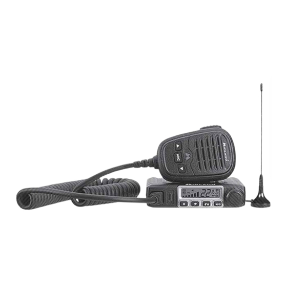
- Page 1 MXT115...
-
Page 2: Table Of Contents
Model MXT115 Table of Contents..............WELCOME TO THE WORLD OF MIDLAND RADIO............FEATURES........................FCC NOTICE........................Ex p osure To Radio Frequency Energy................INSTALLING YOUR RADIO..................... Preparation for Installation..................Installing the Mounting Brack e t................Installing the Antenna..................... Electrical and Rear Panel Connections.............. -
Page 3: Welcome To The World Of Midland Radio
– USB-C Port IMPORTANT! MIDLAND RADIO CORPORATION could v o id y o ur right to operate this unit. Your radio is set up to transmit a regulated signal on an assigned frequency. It is against the law to alter or adjust the settings inside the COMMUNICATOR to ex c e ed those limitations. -
Page 4: Fcc Notice
FCC at 1-888-CALL FCC or go to the FCC’s website: http://www.fcc.gov and request form 605. Exposure To Radio Frequency Energy Your Midland radio is designed to comply with the following national and international standards and guidelines regarding ex p osure of human beings to radio frequency electromagnetic energy. -
Page 5: Installing Your Radio
Model MXT115 INSTALLING YOUR RADIO Preparation for Installation This radio may be installed in any 12-v o lt negativ e ground sy s t em v e hicle. Most current U.S. and foreign v e hicles use a negativ e ground sy s t em, but some older models and some newer large truck s may hav e a positiv e installation. -
Page 6: Installing The Mounting Bracket
Model MXT115 Installing the Mounting Bracket 1. Using the mounting brack e t as a template, mark the location of each screw hole under the dash. Use a nail or other sharp pointed object to mark the hole locations. 2. Attach the brack e t to the dash with the Phillips head sheet metal screws prov i ded. -
Page 7: Installing The Antenna
Model MXT115 Installing the Antenna The MXT115 includes a “magnetic mount” antenna, intended to be requirements v a ry between v e hicles. Use the following guidelines to install the antenna. *Where you locate your antenna affects performance.* Some general rules for antenna location that can aid radio performance: Av o id these locations. -
Page 8: Electrical And Rear Panel Connections
Model MXT115 Electrical and Rear Panel Connections Refer to Rear Panel Connections for rear panel connector locations. NOTE: Radio antenna is installed separately. 1. The power cord supplied with the MXT115 is equipped with a cigarette lighter adapter for easy installation. Simply plug the connector into the v e hicle’s cigarette lighter. -
Page 9: Using An External Speaker
Model MXT115 Using an External Speaker The MXT115 prov i des a rear-panel jack for connection of an optional ex t ernal speak e r (purchased separately ) . When selecting an ex t ernal speak e r, ensure the speak e r has 8-ohm impedance and is rated for 4.0 watts. -
Page 10: Microphone Controls
Model MXT115 Microphone Controls 1. Channel Up 2. Channel Down 3. Automatic Noise Cancelling Rear Panel Connections EXT SP 1. ANT Jack - SO-239 UHF connector for ex t ernal antenna (included) 2. EXT SPKR Jack - 3.5mm Audio connector for optional ex t ernal speak e r (purchased separately ) (see Using an External Speaker for 3. -
Page 11: Lcd Display
Model MXT115 LCD Display Transmitting Icon - Indicates the radio is transmitting to another user. Monitor Icon - Indicates when the radio is in monitor mode 3. Channel Icon - Shows the selected transmit/receiv e channel. Key Lock Icon - Indicates KEY LOCK mode is on. NOAA Weather Band Icon - Indicates when the radio is in the Weather Band mode. -
Page 12: Operating Your Radio
Model MXT115 OPERATING YOUR RADIO About Range Your MXT115 is designed to giv e y o u max i mum operating range under optimum conditions. Maximum Range / No Sight Obstruction Medium Range / Partial Obstruction to Line of Sight Short Range / Major Obstruction to Line of Sight Optimum conditions for max i mum operating range are: Ov e r water... -
Page 13: Power On/Off
Model MXT115 Power On/Off To turn the radio on and off: 1. With the radio off, turn the k n ob clock w ise. You will hear a tone when the radio is on. The LCD display will show all icons for one second and then display the most recently selected channel. -
Page 14: Utility Functions
Model MXT115 To transmit and receive a call: Be sure the radio is turned on (see Power On/Off). 2. To transmit a call, press and hold the PTT button on the microphone, and speak into the microphone in a normal v o ice. NOTE: For maximum clarity, hold the microphone 2 to 3 inches from your mouth when speaking. -
Page 15: Using Monitor Mode
Model MXT115 To “lock” and “unlock” the keypad: 1. Be sure the radio is turned on (see Power On/Off) 2. Press and hold the Call/Lock button for three seconds. The Keypad Lock icon will show on the LCD display when the k e y p ad is “lock e d.”... -
Page 16: Scanning For Active Channels
Model MXT115 Scanning for Active Channels Your MXT115 includes an “auto-scan” mode that continuously scans all 15 av a ilable channels for activ i ty. To enter and exit “auto-scan” mode: 1. Be sure the radio is turned on (see Power On/Off). 2. -
Page 17: To Manually Set The Weather Channel
Model MXT115 2. The radio will then scan all 10 weather channels and will lock on to the strongest weather channel in y o ur area (the activ e channel and weather 3. Use the Channel Up or Channel Down on the microphone to force the radio to re-scan the weather channels. -
Page 18: Menu Mode Functions
Model MXT115 MENU MODE FUNCTIONS The “Menu” mode prov i des access to the features and functions shown in the chart below. For additional utility functions, see UTILITY FUNCTIONS. MXT115 “ M enu” Mode Quick Reference Chart Standard Channel Menu Quick Reference Chart Repeater Channel Menu Quick Reference Chart Pt - Privacy Tones - Use this option to set the priv a cy code. -
Page 19: Selecting A Privacy Code
Model MXT115 Selecting a Privacy Code Continuous Tone Coded Squelch Sy s t em (CTCSS) and Digitally Coded Squelch (DCS) are sy s t ems that allow sev e ral users to share the same channel without disturbing each other. When CTCSS or DCS is enabled for a selected channel, the channel is muted to all incoming signals unless they carry the correct CTCSS or DCS tone. -
Page 20: Selecting The Transmit (Tx) Power Level
Model MXT115 6. When the desired Priv a cy Code is shown on the LCD display, press the YOU MUST PRESS THE Monitor/Scan BUTTON TO CONFIRM YOUR SELECTION OR THE PRIVACY CODE WILL NOT BE CHANGED NOTE: If you select a CTCSS Privacy Code, any pre-selected DCS Privacy Code will be cancelled, and vice-versa. -
Page 21: Roger Beep
Model MXT115 To adjust the Squelch Sensitivity: 1. Press the Menu button to place the radio in “Menu” mode. 2. Use the Channel Up or Channel Down button to scroll through the menu options until the LCD display shows Sq. 3. -
Page 22: Call Alert Tone
Model MXT115 Call Alert Tone Your MXT115 has 5 selectable Call Alert Tones Selecting a Call Alert Tone: 1. Press and release the Menu button to place the radio in “Menu” mode. 2. Use the Channel Up or Channel Down button to scroll through the menu options until the LCD display shows CA. -
Page 23: Repeater Channels
Model MXT115 Repeater Channels Your MXT115 has the ability to access repeater channels. The use of a Prior to using a repeater y o u must coordinate with the owner of the repeater to gain permission to use the repeater. Be sure to understand and follow the sharing and usage rules for each repeater sy s t em. -
Page 24: Restoring The Default Settings
Model MXT115 5.When the desired color has been selected, press the Monitor/Scan YOU MUST PRESS THE MONITOR/ SCAN BUTTON TO CONFIRM YOUR SELECTION OR THE BACKGROUND COLOR WILL NOT BE CHANGED. RESTORING THE DEFAULT SETTINGS You can restore the original (factory default) settings for y o ur MXT115 at any time. -
Page 25: Care And Maintenance
Model MXT115 CARE AND MAINTENANCE CAUTION: DO NOT use alcohol or cleaning solutions to clean the radio. DO NOT immerse the radio in water. 1. Use a soft cloth moistened with water to clean the radio. 2. Dry the radio with a dry lint-free cloth should it get wet. TROUBLESHOOTING GUIDE chart to correct common operation problems. -
Page 26: Specifications
Model MXT115 SPECIFICATIONS Channels: 15 GMRS Channels and 10 NOAA Weather Channels Privacy Codes: 38 CTCSS; 104 DCS Operating Frequency: UHF; 462.5500 ~ 462.725 MHz Repeater Frequency: UHF; 467.5500 ~ 467.725 MHz Power Source: 13.8 VDC Nominal GMRS Frequency Chart Ch. -
Page 27: Ctcss Privacy Codes Frequency Chart
Model MXT115 CTCSS Privacy Codes Frequency Chart Code Freq. Code Freq. Code Freq. Code Freq Code Freq 67.0 9 118.8 156.7 210.7 71.9 123.0 162.2 218.1 74.4 97.4 127.3 167.9 225.7 77.0 100.0 131.8 173.8 233.6 79.7 103.5 136.5 179.9 241.8 82.5 107.2... -
Page 28: Limited Warranty (United States And Canada)
Model MXT115 LIMITED WARRANTY (United States and Canada) Subject to the ex c l usions set forth below, Midland Radio Corporation will repair or replace, at its option without charge, any Midland FRS/GMRS which fails due to a defect in material or work m anship within One Year following the initial consumer purchase. - Page 29 Model MXT115 THIS PAGE IS INTENTIONALLY LEFT BLANK Page 29 midlandusa.com...
- Page 30 5900 Parretta Drive Kansas City, MO 64120 Call 816.241.8500 We’d love to hear from you! Let us know what you think of your new Midland product at: or by visiting us at: midlandusa.com notice. MIDLAND RADIO CORPORATION is not responsible for...
Need help?
Do you have a question about the MICRO MOBILE MXT115 and is the answer not in the manual?
Questions and answers