Table of Contents
Advertisement
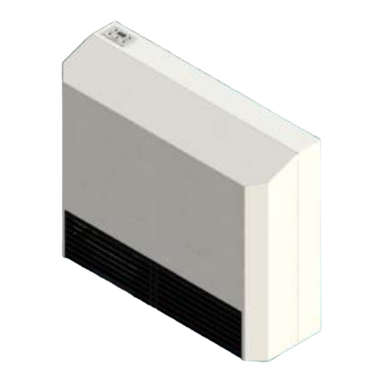
Owner's Manual
17,500 Btu/hr.
WARNING: Improper installation, adjustment,
alteration, service, or maintenance can cause
injury or property damage. Refer to this manual.
For assistance or additional information, consult
a qualified Installer, service agency or the gas
supplier.
WARNING: This direct-vent furnace is approved for aftermarket manufactured home installations (once the
manufactured home is sold, installed and stationary) unless prohibited by local codes. Not for manufactured home
manufacturer (factory) installation. Do not install any of these furnaces (natural or L.P. Gas) in trailers or recreational
vehicles.
Williams Comfort Products.
2
Direct-Vent Wall Furnace
Model Numbers:
1753012
FOR USE WITH NATURAL GAS ONLY
Model Numbers:
1753011
FOR USE WITH PROPANE GAS ONLY
READ THIS OWNER'S MANUAL CAREFULLY BEFORE YOU
INSTALL YOUR NEW WILLIAMS WALL FURNACE.
WARNING:
instructions is not followed exactly, a fire or
explosion
damage, personal injury or loss of life.
– Do not store or use gasoline or other
– WHAT TO DO IF YOU SMELL GAS:
– Installation
250 West Laurel Street
Save this manual for future reference.
High Efficiency
If the information in these
may
result
flammable vapors and liquids in the
vicinity of this or any other appliance.
• Open all windows
• Do not try to light any appliance.
• Do not touch any electrical switch.
• Do not use any phone or cell phone in
your building.
• Extinguish any open flame.
• Immediately call your gas supplier from
a neighbor's phone. Follow the gas
supplier's instructions.
• If you cannot reach your gas supplier,
call the fire department.
and
performed by a qualified installer, service
agency or the gas supplier.
Colton, California 92324 U.S.A.
causing
property
service
must
be
Advertisement
Table of Contents

Subscribe to Our Youtube Channel
Related Manuals for Williams 1753012


Summary of Contents for Williams 1753012
- Page 1 FOR USE WITH NATURAL GAS ONLY Model Numbers: 1753011 FOR USE WITH PROPANE GAS ONLY READ THIS OWNER’S MANUAL CAREFULLY BEFORE YOU INSTALL YOUR NEW WILLIAMS WALL FURNACE. WARNING: If the information in these instructions is not followed exactly, a fire or explosion...
-
Page 2: Your Williams Warranty
Warranty & Installation Record – 3 Warranty The manufacturer, Williams Comfort Products, warrants this wall furnace or heater to the original purchaser under the following conditions: LIMITED ONE-YEAR WARRANTY 1. Any part thereof which proves to be defective in material or workmanship within one year from date of original purchase for use will be repaired or replaced at the Manufacturer’s option, FOB, to its factory. -
Page 3: Table Of Contents
Table of Contents Your Williams Warranty ..............2 Installation Record ................. 2 Table of Contents ................3 Safety Rules .................. 4 Introduction ..................5 Description ..................5 Tools Needed ................5 Materials ..................5 Helpful Installation Information ............5 Optional Accessories ..............5 Installation ................ -
Page 4: Safety Rules
Safety Rules BE SURE to provide for adequate combustion and ventilation air. The flow of this air to the furnace must not WARNING: READ THESE RULES AND THE be blocked. INSTRUCTIONS CAREFULLY. FAILURE 10. NEVER vent flue gases into another room, a fireplace or FOLLOW THESE RULES AND INSTRUCTIONS any space inside a building. -
Page 5: Introduction
Introduction – 6 Introduction Please read our instructions before you install and use your furnace. This will help you obtain the full value from this furnace. It will also help you avoid any needless service costs if the problem is found within this instruction manual. Always consult your local heating or plumbing inspector, building department or electric utility company regarding regulations, codes or ordinances which apply to the installation of a Direct-Vent Wall Furnace. -
Page 6: Installation
Installation Locating Wall Furnace Note: When installing the furnace directly on carpeting or other After selecting a location that meets the requirements, inspect combustible material (excluding wood flooring), it must be the wall, floor and outside areas. Make sure there are no pipes, installed on a metal or wood panel extending the full width and wiring, or anything else that would interfere with furnace, vent depth of the furnace. - Page 7 Installation To avoid electrical shock, turn off all electrical circuits that pass Drill a 1/4 inch hole in the wall at the vent opening center mark all through the wall where you are going to install the furnace. the way through to the outside. Cut the 2-1/2 inch diameter hole Before the furnace is installed, an opening must be cut through through the inside wall.
- Page 8 Installation Optional Air Inlet Kit (Figure 7-9) If using the optional air inlet kit 9310, install the O-Ring gasket FIGURE 5 provided in the kit shown in figure 8. Figure 7 shows the standard Inlet pipe stop bracket; this will prevent the PVC pipe from being pushed too far into the back of the furnace.
-
Page 9: Thermostat Installation
Installation FIGURE 8 Optional External Thermostat Installation P322016 Wall Mounting 1. If an existing thermostat is being replaced and is in a satisfactory location and the wiring is in good condition, use existing wiring. If in doubt, use new wiring. 2. - Page 10 Installation Optional External Thermostat Mounting 5. Replace the thermostat cover. 1. To remove the thermostat cover, grasp cover and squeeze Note: Refer to the installation instructions packed in the both sides firmly, and then lift to remove cover. Carefully thermostat carton if you have any doubt about the above remove and discard the packing tab protecting the switch procedures.
-
Page 11: Cabinet Installation
Installation Venting Exhaust Piping and Termination (Figure 13-21) FIGURE 14 Up to 50 Feet of equivalent vent length may be used. Use Schedule 40 Standard Wall 2” PVC meeting ASTM Standard D1784. For Canada, ULC S636 approved duct must be used. Use a 45°... - Page 12 Installation FIGURE 16 FIGURE 18 FIGURE 19 FIGURE 17...
- Page 13 Installation Direct Venting- Optional Air Inlet Kit 9310 (Figure 22-25) Because this unit is a high efficiency furnace, a condensate trap and drain hose is provided with the unit (see Fig. 20). The Use a 90° elbow as the vent termination for the inlet pipe. hose must be drained either to the outside or to a drain inside the home.
-
Page 14: Gas Supply And Piping
Installation FIGURE 24 FIGURE 25 Gas Supply and Piping Orifice Sizes The gas control valve is shipped with a sealed cover over the gas inlet tapping. Do not remove seal until you are ready to The efficiency rating of these appliances is a product thermal connect piping. - Page 15 Installation FIGURE 26 All piping must comply with local codes and ordinances or with the National Fuel Gas Code (ANSI Z223.1 NFPA No. 54), whichever applies. (In Canada: CAN/C.G.A B149). Refer to Figure 14 for the general layout of the unit. It shows the basic fittings needed.
- Page 16 Installation FIGURE 28 Checking the Gas Piping FIGURE 29 Test all piping for leaks. When checking gas piping to the Gas Pipe Sizes furnace with gas pressure at less than 1/2 PSI, shut off manual gas valve to the furnace. If the gas piping is to be checked with Natural Gas the pressure at or above 1/2 PSI, the furnace and manual Pipe Capacity –...
- Page 17 Installation The furnace operates in the following sequence: Input and output ratings shown on the rating plate, located in burner compartment, must not be exceeded. 1. The control turns on the main burner. IMPORTANT: KEEP BURNER CONTROL 2. Heat builds up in the furnace and starts the fan. The heated COMPARTMENT CLEAN BY CLEANING REMOVABALE air comes out the panel louvers.
-
Page 18: Operating Your Furnace
Operating Your Furnace Operating Instructions 1. STOP! Read the safety information above. 2. Make sure there is power to the unit; the furnace is supplied with a 3-prong 120VAC power cord. The internal switches must be on (see fig. 31 and 32) FIGURE 31 FIGURE 32 3. - Page 19 Operating Your Furnace 4. Remote Mode: The furnace can be operated by the FIGURE 36 external optional wall thermostat P322016 or optional remote control P323453. To initiate this mode, press the Mode select button on the display panel once from off mode to display “- -“(see fig.
-
Page 20: Start-Up Procedure
Operating Your Furnace Start-Up Procedure Start the furnace using the procedures in the section the seconds per cubic foot of gas being delivered to the “Operating Your Furnace”. furnace. 3. Assuming natural gas with a heating valve of 1,000 Btu per WARNING: Danger of bodily injury or death. -
Page 21: How To Care For Your Furnace
How to Care for Your Furnace Cabinet Finish WARNING: If flame appears abnormal, contact company qualified service Clean the cabinet with a damp cloth. Never use abrasive technician immediately. cleaners. Cabinets are finished in heat-resistant powder paint. DO NOT refinish. Condensate Trap (Fig. -
Page 22: Replacement Parts List
Installations in the State of Massachusetts Be either hardwired or battery powered or both; and Shall comply with NFPA 720 (2005 Edition). 3. A product approved vent terminal must be used, and if applicable, a product approved air intake must be used. Installation shall be in strict compliance with the manufacturer's instructions. - Page 23 Replacement Parts List 6H31 Front Panel P323465 Nylon PCB Standoff P323481 Inducer Fan Mounting Screw P323459 Fan Motor P323460 Blower Wheel...
- Page 24 Page left blank intentionally...
- Page 25 Page left blank intentionally...
-
Page 26: Wiring Diagram
Wiring Diagram... -
Page 27: Troubleshooting
Troubleshooting SYMPTOM POSSIBLE CAUSE CORRECTIVE ACTION 1. Furnace operates, A. External thermostat location. Check the thermostat location. It should not be but turns "OFF" in the path of warm air discharge from the before room furnace, near a lamp or above a T.V. or stereo temperature is set. -
Page 28: Hints And Information
3. Part number 4. Part description All parts listed herein may be ordered from your equipment supplier. The model number of your Williams wall furnace will be found on the name plate. Williams Comfort Products • 250 West Laurel Street, Colton, CA 92324 (909) 825-0993 •...
Need help?
Do you have a question about the 1753012 and is the answer not in the manual?
Questions and answers