Williams 3144030 Owner's Manual
Electric counterflow wall heater
Hide thumbs
Also See for 3144030:
- Brochure & specs (2 pages) ,
- Brochure & specs (2 pages) ,
- Owner's manual (21 pages)
Table of Contents
Advertisement
Quick Links
Owner's Manual
The Manufacturer, Williams Heater Co., warrants this wall heater or heater to the original purchaser under the following conditions:
Williams Furnace Co. 250 West Laurel Street Colton, California 92324 U.S.A.
LIMITED ONE-YEAR WARRANTY
Save this manual for future reference.
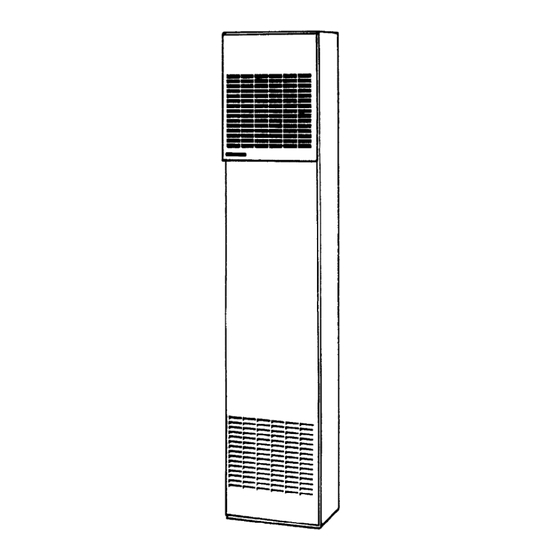
Electric Counterflow
Wall Heater
Model Number:
3144030
READ THIS OWNER'S MANUAL CAREFULLY BEFORE YOU
INSTALL YOUR NEW WILLIAMS WALL HEATER.
WARNING: Failure to comply with
instructions could result in personal injury,
property damage and/or death.
– Do not store or use gasoline or other
flammable vapors and liquids in the vicinity of
this or any other appliance.
– If you smell smoke:
Danger of electrical shock
• Do not touch heater.
• Immediately shutdown main electrical
supply to heater.
• Extinguish any open flame.
• Contact a qualified installer or service
agency.
1
Advertisement
Table of Contents

Related Manuals for Williams 3144030


Summary of Contents for Williams 3144030
- Page 1 • Contact a qualified installer or service agency. The Manufacturer, Williams Heater Co., warrants this wall heater or heater to the original purchaser under the following conditions: Williams Furnace Co. 250 West Laurel Street Colton, California 92324 U.S.A.
-
Page 2: Your Williams Warranty
Warranty The Manufacturer, Williams Heater Co., warrants this wall heater or heater to the original purchaser under the following conditions: LIMITED ONE-YEAR WARRANTY 1. Any part thereof which proves to be defective in material or workmanship within one year from date of original purchase for use will be repaired or replaced at the Manufacturer’s option, FOB, its factory. -
Page 3: Table Of Contents
Contents Your Williams Warranty .............. 2 Installation Record ..............2 Table of Contents ................ 3 Safety Rules ................. 4 Introduction ................. 5 Description ..................5 Tools Needed ................5 Materials ..................5 Helpful Installation Information ............5 Optional Accessories ..............5 Installation ................ -
Page 4: Safety Rules
Safety Rules ALERT children and adults to the hazards of high surface WARNING: READ THESE RULES AND THE temperature and to keep away to avoid burns or clothing INSTRUCTIONS CAREFULLY. FAILURE TO ignition. FOLLOW THESE RULES AND INSTRUCTIONS COULD CAUSE A MALFUNCTION OF THE 10. -
Page 5: Introduction
Introduction – 5 Introduction Please read our instructions before you install and use your heater. This will help you obtain the full value from this heater. It will also help you avoid any needless service costs if the problem is something we cannot control and cannot cover in our Warranty. Always consult your local Heating Inspector, Building Department or Electric Utility company regarding regulations, codes or ordinances which apply to the installation of an Electric Heater. -
Page 6: Installation
Installation Installing Your Wall Heater The following steps are all needed for proper installation and safe If you have any doubts as to any requirements, check with local operation of your heater. authorities for local and state codes affecting the installation. Always obtain professional help where needed. -
Page 7: Locating Wall Heater And Thermostat
Installation Locating Wall Heater and Thermostat Consider the following points before attempting to install the 9. After picking a location that meets the requirements, heater: inspect the wall. Make sure there are no pipes, wiring, or anything else that would interfere with heater or thermostat 1. -
Page 8: Recessed Mount Installation
Installation Recessed Mount Installation BEFORE YOU BEGIN: To avoid electrical shock, turn off electrical circuits that pass through the wall where you are going to install the heater. If you intend to use the optional rear outlet, turn to page 12 for rear outlet installation procedure before you begin to install the heater. Use only the optional grille and boot extension supplied by the manufacturer. -
Page 9: Surface-Mount Installation
Installation NOTE FIGURE 5 – Close Off Stud Space Flexible conduit may be used only if approved by your local codes and ordinances. If you have any doubt, consult your local Electrical or Building Inspector. 5. The electrical supply wires, ground wire and the thermostat wires may now be routed to the heater location. -
Page 10: Thermostat Installation
Installation Thermostat Installation 1. If an old thermostat is being replaced, is in a satisfactory location and the wiring appears to be in good condition, use FIGURE 6 – Route Thermostat Cable existing wiring. If in doubt, use new wire. 2. -
Page 11: Mounting Your Heater
Mounting Your Heater NOTE If you are using the optional rear outlet, follow the installation FIGURE 7 – Heater Mounting instructions on page 12 before proceeding. If recessed mounted, clear recess of all debris. Place heater into position. Be sure to drop flex conduit through hole provided in top of heater. -
Page 12: Installing Your Rear Outlet Accessory
Installing Your Rear Outlet Accessory Recessed Mount Heater FIGURE 8 – Plaster Ground Position Cut 8-¼ inch x 12-¼ inch hole in wall as shown in Figure 3 on page 8 Cut 8 inch x 12 inch opening in back of cabinet following scored lines stamped on the cabinet. -
Page 13: Electrical Connections
Electrical Connections Connect the thermostat wires to the two (thermostat) wires WARNING: extending inside the junction box. Refer to wiring diagram on DANGER OF PROPERTY DAMAGE, junction box cover plate and Figure 11. BODILY INJURY OR DEATH. When heater mounting has been completed, see steps 1, 2 and 3 below. -
Page 14: Installing Your Trim Strip Accessory
Installing Your Trim Strip Accessory Trim Strip Accessory 4701 NOTE When desired, optional Trim Strip Kit may be used to cover the Quarter-round wood molding may be used for trim if desired. crack between heater and wall See Figure 12. Trim Cover (Surface Mount) Place strips tight against heater with other edge against wall surface and fasten to wall with escutcheon pins provided. -
Page 15: Operating Your Heater
Operating Your Heater The heater is controlled by means of 24 volt, wall-mounted Air volume may be adjusted at the operational rear grilles, if so thermostat. When the thermostat circuit is energized, low equipped. Do not attempt to reduce flow of air from main panel voltage relays are actuated which close circuits to the heating (front) grille. -
Page 16: Wiring And Technical Information
Wiring and Technical Information Model 3144030 Technical Information MOTOR AND FAN DATA SPECIFICATIONS AND DIMENSIONS Voltage 240 1Ø Model 3144030 Voltage 60 A.C. 60 A.C. HP (approx.) 1 / 40 RPM (approx.) 1000 CFM (approx.) 38.3 Btu/hr. 31,400 CONTROL DATA Width 14-1/8”... -
Page 17: Order Replacement Parts
Service and Orders – 17 Order Replacement Parts HEATER ASSEMBLY... -
Page 18: Order Replacement Parts
Order Replacement Parts Repair Parts for Model - 3144030 REF. NO. DESCRIPTION PART NO. 16C01 OUTER CASING TOP FRONT PANEL 16B01 BOTTOM FRONT PANEL 16C03 TOP TRIM COVER 16A07 ELEMENT COVER 16A04 JUNCTION BOX ASSEMBLY 16B15 ELEMENT CASING BODY ASSEMBLY... -
Page 19: Service Record
Service and Orders – 19 Service Record Date Maintenance Performed Components Required... -
Page 20: Hints And Information
3. Part number 4. Part description All parts listed herein may be ordered from your equipment supplier. The model number of your Williams wall heater will be found on the name plate. Williams Furnace Company • 250 West Laurel Street, Colton, CA 92324 (909) 825-0993 •...
Need help?
Do you have a question about the 3144030 and is the answer not in the manual?
Questions and answers