Williams 1773512 Installation Instructions And Owner's Manual
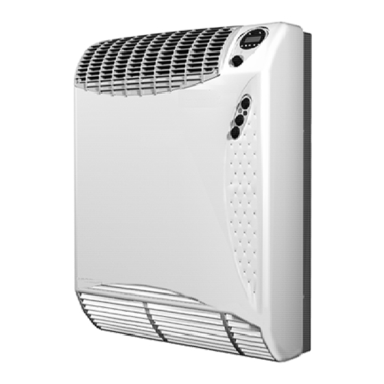
Natural gas only direct-vent wall furnace
Hide thumbs
Also See for 1773512:
- Brochure & specs (2 pages) ,
- Installation instructions and owner's manual (25 pages) ,
- Owner's manual (28 pages)
Table of Contents
Advertisement
MODEL:
Natural Gas Only
1773512
MODEL:
Propane Gas Only
1773511
WARNING: Improper installation, adjustment,
alteration, service, or maintenance can cause
injury or property damage. Refer to this
manual. For assistance or additional
information, consult a qualified installer,
service agency or the gas supplier.
WARNING: Installation and repair must be
done by a qualified service person. The
furnace should be inspected before use and at
least annually by a professional service
person.
WARNING: If not installed, operated and
maintained in accordance with the
manufacturer's instructions, this
product could expose you to substances in
fuel or from fuel combustion which can cause
death or serious illness and which are known
to cause cancer, birth defects or other
reproductive harm.
Williams Furnace Co., 250 West Laurel Street, Colton, CA 92324 U.S.A.
Installation Instructions and Owner's Manual
Direct-Vent Wall Furnace
WARNING: If the information in this
manual is not followed exactly; a fire
or explosion may result, causing
property damage, personal injury or
loss of life.
- Do not store or use gasoline or other
flammable vapors and liquids in the
vicinity of this or any other appliance.
- WHAT TO DO IF YOU SMELL GAS
• Open all windows.
• Do not try to light any appliance.
• Do not touch any electrical switch.
• Do not use any phone in your building.
• Extinguish any open flame.
• Immediately call your gas supplier
from a neighbor's phone. Follow
the gas supplier's instructions.
• If you cannot reach your gas supplier,
call the fire department.
- Installation and service must be
performed by a qualified installer,
service agency or the gas supplier.
Advertisement
Table of Contents

Subscribe to Our Youtube Channel
Related Manuals for Williams 1773512


Summary of Contents for Williams 1773512
- Page 1 - Installation and service must be death or serious illness and which are known performed by a qualified installer, to cause cancer, birth defects or other service agency or the gas supplier. reproductive harm. Williams Furnace Co., 250 West Laurel Street, Colton, CA 92324 U.S.A.
-
Page 2: Table Of Contents
Table of Contents General Information and Technical Data Instructions to Installer ..........................2 Safety Rules and General Warnings......................2 Technical Data ............................4 Installation Wall Installation ............................5 Installations in the State of Massachusetts ....................5 Outside Location for Vent Terminal ......................7 Gas Conversions............................ -
Page 3: Safety Rules And General Warnings
Safety Rules and General Warnings DO NOT OPERATE THIS FURNACE WITHOUT FRONT PANEL INSTALLED Due to high temperatures, the furnace should be More frequent cleaning may be required due to excessive • • located traffic away from lint from carpeting, bedding materials, etc. It is imperative combustible materials such as furniture and that control compartments, burners and circulating air draperies. -
Page 4: Technical Data
Some Points to Remember Learn to recognize the odour of LP Gas. Your local LP Gas dealer can give you a "Scratch and Sniff" pamphlet. Use it to • find out what the propane odour smells like. If you suspect that your LP Gas has a weak or abnormal odour, call your LP Gas dealer. -
Page 5: Installation
Installation Installation should be done by a QUALIFIED SERVICE TECHNICIAN. The furnace must be located on an outside wall. Wall Installation Minimum clearances from combustible materrials: WARNING: For the installation of this furnace, the • Unit to the top surface of carpeting, tile: 2-inches (50 mm) following items must be used as a vent air intake system: •... - Page 6 b. Be either hard-wired or battery powered or both; and c. Shall comply with NFPA 720 (2005 Edition). A product-approved vent terminal must be used, and if applicable, a product-approved air intake must be used. Installation shall be in the strict compliance with the manufacturer’s instructions. A copy of the installation instructions shall remain with the appliance or equipment at the completion of the installation.
-
Page 7: Outside Location For Vent Terminal
Outside Location for Vent Terminal Upon delivery, check to make sure the packaging has not been damaged. 1. Remove the furnace from box/packaging taking care not to damage the paper template to be used to mark the holes for mounting the furnace. 2. - Page 8 8. Place the adhesive spongy lining behind the unit. (Figure 4) 9. Attach the flue exhaust pipe end (diameter 1-3/8”) on the furnace male pipe connection (Figure 5). BE SURE THAT THE RUBBER SILCONE O-RING GASKET IS IN POSITION. 10. Install the unit to the wall leaning the bottom edge of panel “C” (where the fan is located) on the supporting frame. (Figure 6) Attach the furnace to the support bracket with the two screws.
-
Page 9: Gas Conversions
Figure 7 Gas Conversions Converting to another gas type must be performed by a qualified service technician. If the type of the gas supplied to the dwelling is not the same type as your furnace (natural or LPG gas), it must be converted. It will be necessary to do the following: 1. -
Page 10: Gas Supply
4. Check the gas pressure and settings. Minimum Burner Pressure Setting a. Set LOW burner capacity by pressing button Z2 b. Connect a micro manometer to the test gauge B (Figure 8) c. Rotate the internal screw “D” (Figure 8) and set the pressure at the correct value Maximum Burner Pressure Setting: a. - Page 11 High Altitude Adjustment Based on the altitude of the installation site, reduce the manifold pressure specified in the “Technical Data” chart and as shown in the table below: Manifold Pressure Altitude Reduction Rate 0-2,000 ft 2,000-3,000 ft 3,000-4,000 ft 4,000-5,000 ft 5,000-5500 ft First Firing the Furnace Start the furnace following the instructions given in the “Operating Instructions”.
-
Page 12: Electrical Wiring Diagram
Electrical Wiring Diagram Key: EV, EV1 Gas Valve 1 (Safety Shutter) Vanne Gas 1 (Securite’) Hi-Lo Flame Operator Operateur Haute-Basse Flamme Fan Motor Moteur du Ventilateur Overheat Thermostat Thermostat de Surchauffe Fan Thermostat Thermostat de Ventilation Mains Fuse – 5x20 size – 4A Pressostat de Circuit De Combustion Flame Sensor Electrode de Detection de Flamme... -
Page 13: Operating Instructions
Operating Instructions Before operating the furnace, read carefully all warnings and safety information in this manual. FOR YOUR SAFETY READ BEFORE OPERATING WARNING: If you do not follow these instructions exactly, a fire or explosion may result causing property damage, personal injury or loss of life. A. - Page 14 WHAT TO DO IF THE RED LAMP IS LIT This appliance has an electronic flame supervision device. If the flame disappears the gas flow will be automatically shut off and the red lamp will light instead of the green one. The appliance will attempt to relight if you do ONE of the following: Turn off the electric supply to the appliance for approximately 40 seconds and turn it on again;...
-
Page 15: Servicing
Servicing All servicing activities must be performed by a qualified service technician or a service agency. The home owner may not service the furnace. The home owner must read this section to be informed of the periodic maintenance and checks that are required. All servicing (except on vent system) must be performed with the external casing removed. -
Page 16: Annual Maintenance Requirements
Annual Maintenance Requirements 1. Clean fan blades. 2. Clean air blower. 3. Check and clean silicone red pipes. 4. Check air flow switch. 5. Clean and check exhaust flue pipe and air intake pipe. Check red O-Ring Gasket (NRNG003). If it is damaged, replace it. -
Page 17: Programmable Timer
Programmable Timer The programmable timer allows precise operating and timing control and is standard on this furnace. (Figure 10) Overview The programmable timer has the following features: Long life lithium battery • Daily and weekly programs • One minute minimum switching time •... -
Page 18: Setting And Adjustment
Setting and Adjustment 1 2 3 4 5 6 7 0:00 Initial Conditions Set the Setting/Regulator switch (Figure 10-B) in RUN position (centre). Press the 1 2 3 4 5 6 7 Reset button R. The display will flash. E EE With the Setting/Regulator switch selector in position (right), press the Reset button, R, the display error EEE will appear. - Page 19 E. To set further programs repeat steps item B through D above. NOTE: When the same ON and OFF times are desired for different days of the week, the setting procedure may be simplified. 1-2-3-4-5 (from Monday through Friday) • 1-2-3-4-5-6 (from Monday through Saturday) •...
-
Page 20: Troubleshooting
Troubleshooting Starting Sequence (Electrical) Step 1 1. Check L1 – L2 (Supply 120 V, 60 Hz) 2. Check M9 (Main fuse) Troubleshooting Step 1 Point 1 (L1-L2) No voltage (120 V). Check the electrical supply line, wiring and connections. Point 2 (M9) Fuse damaged. - Page 21 Troubleshooting Step 3 Point 5 (Z1) Z1 is open and no ignition. Check wiring and connections. If everything is okay, replace the switch. Point 7 (M2) closed thermostat temperature is lower than 104 °F. Check wiring and connections. If they are okay, replace the thermostat.
- Page 22 Point 13 (TR) No inlet voltage (120 V). Check 5 pole connector and control box. If everything is okay, first replace the connector and then the control box if problem remains. No outlet voltage (24 V) during ignition. Check wiring and connections. If everything is okay, replace the transformer.
-
Page 23: Replacement Parts
Replacement Parts TR – 120/24V Transformer Part Number: P332523 Ignition Control Box Part Number: P332503 NP – Pressure Switch Part Number: P332516 Z9 – Room Thermostat Part Number: P332564 Z1 – Reset and Summer/Winter Part Number: P332630 Switch Z8-Z3 – Timer and Manual- Part Number: P332629 Program Mode Switch Electric Box... - Page 24 Part Number: P332565 M2 - Fan Thermostat Part Number: P332496 Fan Blades Part Number: P332572 (Left) (4 pieces) P332638 (Right) M - Fan Motor Part Number: P332513 (2 Pieces) November 2015 Williams Furnace Co., 250 West Laurel Street, Colton, CA 92324 U.S.A.
Need help?
Do you have a question about the 1773512 and is the answer not in the manual?
Questions and answers