Williams 2903512 Installation Instructions And Owner's Manual
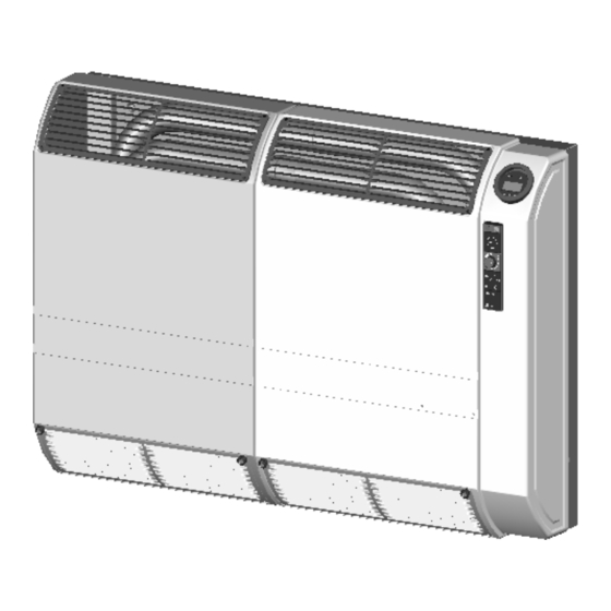
Williams 2903512; 2903511 direct-vent wall furnace
Hide thumbs
Also See for 2903512:
- Brochure & specs (2 pages) ,
- Installation instructions and owner's manual (24 pages)
Table of Contents
Advertisement
Quick Links
MODEL:
Natural Gas Only
2903512
MODEL:
Propane Gas Only
2903511
WARNING: Improper installation, adjustment,
alteration, service, or maintenance can cause
injury or property damage. Refer to this
manual. For assistance or additional
information, consult a qualified installer,
service agency or the gas supplier.
WARNING: Installation and repair must be
done by a qualified service person. The
furnace should be inspected before use and at
least annually by a professional service
person.
WARNING: If not installed, operated and
maintained in accordance with the
manufacturer's instructions, this
product could expose you to substances in
fuel or from fuel combustion which can cause
death or serious illness and which are known
to cause cancer, birth defects or other
reproductive harm.
Williams Furnace Co., 250 West Laurel Street, Colton, CA 92324 U.S.A.
Installation Instructions and Owner's Manual
Direct-Vent Wall Furnace
WARNING: If the information in this
manual is not followed exactly; a fire
or explosion may result, causing
property damage, personal injury or
loss of life.
- Do not store or use gasoline or other
flammable vapors and liquids in the
vicinity of this or any other appliance.
- WHAT TO DO IF YOU SMELL GAS
• Open all windows.
• Do not try to light any appliance.
• Do not touch any electrical switch.
• Do not use any phone in your building.
• Extinguish any open flame.
• Immediately call your gas supplier
from a neighbor's phone. Follow
the gas supplier's instructions.
• If you cannot reach your gas supplier,
call the fire department.
- Installation and service must be
performed by a qualified installer,
service agency or the gas supplier.
Advertisement
Table of Contents

Related Manuals for Williams 2903512


Summary of Contents for Williams 2903512
- Page 1 - Installation and service must be death or serious illness and which are known performed by a qualified installer, to cause cancer, birth defects or other service agency or the gas supplier. reproductive harm. Williams Furnace Co., 250 West Laurel Street, Colton, CA 92324 U.S.A.
-
Page 2: Table Of Contents
Table of Contents General Information and Technical Data Instructions to Installer ..........................2 Safety Rules and General Warnings......................2 Technical Data ............................4 Installation Wall Installation ............................5 Installations in the State of Massachusetts ....................5 Outside Location for Vent Terminal ......................7 Gas Conversions............................ -
Page 3: Safety Rules And General Warnings
Safety Rules and General Warnings DO NOT OPERATE THIS FURNACE WITHOUT FRONT PANEL INSTALLED • • Due to high temperatures, the furnace should be More frequent cleaning may be required due to excessive located out of traffic and away from combustible lint from carpeting, bedding materials, etc. -
Page 4: Technical Data
Some Points to Remember • Learn to recognize the odor of LP Gas. Your local LP Gas Dealer can give you a "Scratch and Sniff" pamphlet. Use it to find out what the propane odor smells like. If you suspect that your LP Gas has a weak or abnormal odor, call your LP Gas Dealer. -
Page 5: Installation
Installation Installation should be done by a QUALIFIED SERVICE TECHNICIAN. The furnace must be located on an outside wall. Wall Installation Minimum clearances from combustible materials: WARNING: For the installation of this furnace, the • Unit to the top surface of carpeting, tile: 2-inches (50 mm) following items must be used as a vent air intake •... -
Page 6: Figure
b. Be either hard-wired or battery powered or both; and c. Shall comply with NFPA 720 (2005 Edition). A product-approved vent terminal must be used, and if applicable, a product-approved air intake must be used. Installation shall be in the strict compliance with the manufacturer’s instructions. A copy of the installation instructions shall remain with the appliance or equipment at the completion of the installation. -
Page 7: Outside Location For Vent Terminal
Outside Location for Vent Terminal Upon delivery, check to make sure the packaging has not been damaged. 1. Remove the furnace from box/packaging taking care not to damage the paper template to be used to mark the holes for mounting the furnace. 2. - Page 8 Figure 4 O-Ring Gasket Figure 5 Figure 6 12. When the inside installation is complete, proceed to the outside location of the aluminium vent cap on the external wall. The vent cap should perfectly match the pipe end. Mark the location of the three holes for the screw anchors. (Figure 7) The flue grid must be vertical.
-
Page 9: Gas Conversions
Gas Conversions Converting to another gas type must be performed by a qualified service technician. If the type of the gas supplied to the dwelling is not the same type as your furnace (natural or LPG gas), it must be converted. It will be necessary to do the following: 1. -
Page 10: Gas Supply
Gas Supply Check all local codes for requirements, especially for the size and type of gas supply line required. On natural gas lines less than 15” (380 mm) long, use 1/2” tube; on longer runs, use 3/4” iron tube or equal. On LP gas lines, consult LP gas supplier. Installing a New Main Gas Shutoff Valve Each appliance should have its own manual gas shutoff valve. - Page 11 Checking the Gas Inlet Pressure The gas inlet pressure can be measured by connecting a test gauge to the connection provided on the gas valve. (Figure 8 - A) Once installation is complete, the gas inlet pressure must be checked. The minimum gas inlet pressure must be as shown in “Technical Data”.
-
Page 12: Electrical Wiring Diagram
Electrical Wiring Diagram LOW FLAME COIL LOCK-OUT LAMP (RED LAMP) HIGH FLAME COIL TRANSFORMER 120-24 V FAN MOTOR (2 MOTORS) RESET AND SUMMER – WINTER SWITCH (*) OVERHEAT THERMOSTAT HI-LO FLAME AND FAN SPEED SWITCH (*) FAN THERMOSTAT MANUAL – PROGRAM MODE SWITCH (*) MAIN FUSE –... -
Page 13: Operating Instructions
Operating Instructions Before operating the furnace, read carefully all warnings and safety information in this manual. FOR YOUR SAFETY READ BEFORE OPERATING WARNING: If you do not follow these instructions exactly, a fire or explosion may result causing property damage, personal injury or loss of life. A. - Page 14 USING THE FEATURES OF YOUR FURNACE GREEN LAMP : It is lit when the flame is ON. RED LAMP : In case the flame disappears, the gas flow will be shut off and the red lamp will be lit. The furnace is locked-out. To reset the furnace, follow the instructions above, "WHAT TO DO IF THE RED LAMP IS LIT."...
-
Page 15: Servicing
Servicing All servicing activities must be carried out by a qualified service technician or a service agency. The home owner may not service the furnace. The home owner must read this section to be informed of the periodic maintenance and checks the required. -
Page 16: Annual Maintenance Requirements
Annual Maintenance Requirements 1. Clean fan blades. 2. Clean air blower. 3. Check and clean silicone red pipes. 4. Check air flow switch. 5. Clean and check exhaust flue pipe and air intake pipe. Check red O-Ring Gasket (NRNG003). If it is damaged, replace it. -
Page 17: Programmable Timer
Programmable Timer The programmable timer allows precise operating and timing control and is standard on this furnace. (Figure 10) Overview The programmable timer has the following features: • Long life lithium battery • Daily and weekly programs • One minute minimum switching time •... -
Page 18: Setting And Adjustment
1 2 3 4 5 6 7 Setting and Adjustment 0:00 Initial Conditions Set the Setting/Regulator switch (Figure 10-B) in RUN position (centre). Press the 1 2 3 4 5 6 7 Reset button R. The display will flash. ... - Page 19 D. Press the Day Setting, (1……7, Figure 11-D) button to program another day or block of days. E. To set further programs repeat steps item B through D above. NOTE: When the same ON and OFF times are desired for different days of the week, the setting procedure may be simplified. •...
-
Page 20: Troubleshooting
Troubleshooting Starting Sequence (Electrical) STEP 1 1. Check L1 – L2 (Supply 120 V, 60 Hz) 2. Check M9 (Main fuse) TROUBLESHOOTING STEP 1 Point 1 (L1-L2). No voltage (120 V). Check the electrical supply line, wirings and connections. Point 2 (M9). Fuse damaged. - Page 21 WINTER MODE STEP 3 5. Check Z1 (Reset and summer/winter Manual switch). Button up – winter mode. 6. Check Z3 (Manual-automatic switch). Button up – manual mode Button down – auto mode. 7. Check M2 (Fan thermostat). The thermostat is closed only when its Auto temperature is higher than 104 °F.
- Page 22 Point 10 (S). S motor does not run. Check voltage, wirings and connections. If everything is OK, replace the motor. STEP 5 11. Check NP (Pressure switch). 12. Check electrical supply to flame control box (120 V) 13. Check TR (electrical transformer) (120V/24V) 14.
-
Page 23: Replacement Parts
Replacement Parts TR – 120/24V Transformer Part Number: P332523 Ignition Control Box Part Number: P332503 NP – Pressure Switch Part Number: P332516 Z9 – Room Thermostat Part Number: P332564 Z1 – Reset and Summer/Winter Part Number: P332571 Switch Z8-Z3 – Timer and Manual- Part Number: P332570 Program Mode Switch Z2- Hi-Lo Flame and Fan Speed... - Page 24 Part Number: P332522 M2 - Fan Thermostat Part Number: P332496 Fan Blades Part Number: P332572 (Left) (4 pieces) P332638 (Right) M - Fan Motor Part Number: P332513 (2 Pieces) April 2015 Williams Furnace Co., 250 West Laurel Street, Colton, CA 92324 U.S.A.
Need help?
Do you have a question about the 2903512 and is the answer not in the manual?
Questions and answers