Advertisement
Quick Links
OWNER'S MANUAL
INSTALLATION INSTRUCTIONS
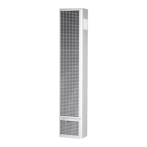
CARMEL
TOP VENT GAS WALL HEATER
SINGLE SIDED MODEL NUMBERS:
TG2030TN (natural gas)
SAVE THIS MANUAL FOR FUTURE REFERENCE.
READ THIS OWNER'S MANUAL CAREFULLY BEFORE YOU
INSTALL YOUR NEW WILLIAMS WALL FURNACE.
WARNING: INSTALLATION IN MANUFACTURED
HOMES Williams Top-Vent Furnaces are allowed in
manufactured homes when the following conditions are met:
- The manufactured home is permanently sited per local codes.
- The manufactured home is manufactured after
6/15/1976 and is HUD approved with a red certification
label (US only). These models are allowed only in
the USA. This applies to aftermarket manufactured
home installations where the home is sold, installed
and permanently sited. Not for manufactured home
manufacturer (factory) installation. These units may not be
installed in trailers or recreational vehicles.
WARNING: This product can expose you to
chemicals including epichlorohydrin which is known to
the State of California to cause cancer and birth defects
and/or other reproductive harm. For information go to
www.p65warnings.ca.gov
WARNING: Improper installation, adjustment,
alteration, service or maintenance can cause injury or
property damage. Refer to this manual. For assistance or
for additional information consult a qualified installer,
service agency or the gas supplier.
250 West Laurel Street, Colton CA 92324
TG2030TN
TM
VISITEZ NOTRE SITE WEB POUR LA VERSION FRANÇAISE DE CE MANUEL
VISITE NUESTRA PÁGINA WEB PARA LA VERSIÓN EN ESPAÑOL DE ESTE MANUAL
https://www.williamscomfortprod.com/products/furnaces/
WARNING: If the information in these instructions
is not followed exactly, a fire or explosion may result
causing property damage, personal injury or loss of life.
- Do not store or use gasoline or other flammable vapors
and liquids in the vicinity of this or any other appliance.
WHAT TO DO IF YOU SMELL GAS:
• Open all windows.
• Do not try to light any appliance.
• Do not touch any electrical switch; do not use
any phone or cell phone in your building.
• Extinguish any open flame.
• Immediately call your gas supplier from a neighbor's
phone. Follow the gas supplier's instructions.
• If you cannot reach the gas supplier, call the fire
department.
– Installation and service must be performed by a
qualified installer, service agency or the gas supplier.
•
www.williamscomfortprod.com
20,000 - 30,000 BTU/hr.
•
1-888-444-1212
Advertisement

Related Manuals for Williams CARMEL TG2030TN


Summary of Contents for Williams CARMEL TG2030TN
- Page 1 INSTALL YOUR NEW WILLIAMS WALL FURNACE. WARNING: INSTALLATION IN MANUFACTURED 20,000 - 30,000 BTU/hr. HOMES Williams Top-Vent Furnaces are allowed in manufactured homes when the following conditions are met: - The manufactured home is permanently sited per local codes. WARNING: If the information in these instructions...
- Page 2 WARRANTY The manufacturer, Williams Furnace Co., warrants this wall furnace Some states do not allow limitation on how long an implied or heater to the original purchaser under the following conditions: warranty lasts, and some states do not allow the exclusion or...
- Page 3 CONTENTS Quick Reference YOUR WILLIAMS WARRANTY Here’s how to: INSTALLATION RECORD TABLE OF CONTENTS INSTALLING YOUR FURNACE Recessed Mount, Surface Mount, SAFETY RULES and Vent Installation are explained starting on page 8. INTRODUCTION BASIC MATERIALS NEEDED OPERATING YOUR FURNACE Igniting your furnace for the first time.
- Page 4 SAFETY RULES or any space inside a building. This could cause property WARNING: Read these rules and the instructions damage, bodily injury or death. carefully. Failure to follow these rules and instructions could cause a malfunction of the furnace. This could result NEVER test for gas leaks with an open flame.
- Page 5 INTRODUCTION The following steps are all needed for proper installation Combustion air is drawn in from the room where the and safe operation of your furnace. If you have any doubts furnace is located and is vented out of the top of the furnace as to any requirements, check with local authorities.
- Page 6 INTRODUCTION Helpful Installation Information Basic Materials Needed The following booklets will help you in making the installation: Pipe and fittings to make gas connections to the furnace. ANSI/NFPA 70, or current edition “National Electrical Code”. Vertical venting materials. See page 15, Figure 8. ...
- Page 7 INSTALLING YOUR FURNACE Locate the furnace near the center of the space to be The following steps are needed for proper installation and heated for good air circulation. Do not put it behind a safe operation of your furnace. If you have any doubts as to any requirements, obtain professional help.
- Page 8 INSTALLING YOUR FURNACE After picking a location that meets the requirements, check After it has been determined that each appliance the walls, attic and roof to make sure there are no obstructions connected to the venting system properly vents when such as pipes, electrical wiring, etc., which could interfere with tested as outlined above, return doors, windows, exhaust the installation of the furnace or vent pipe.
- Page 9 If the furnace is installed in an area with another gas B. Draft Hood Spills appliance(s), the total input rating of all appliances must be If there is spillage at a draft hood (match goes out or flame considered when determining the free area requirements wavers away from draft hood), check for plugged flue for combustion and ventilation air openings.
- Page 10 INSTALLING YOUR FURNACE HOLE PLACEMENT - EXAMPLE EXAMPLES OF GRILL PLACEMENT HOLES FROM VENTILATED VENTILATION GRILLES CONNECTING TWO ATTIC INTO STUD SPACE ROOMS TO MEET UNCONFINED SPACE 100 SQ IN VENTILATION 200 SQ IN MINIMUM GRILLES BETWEEN INTO CLOSET LARGE FOR HOT ROOMS WATER...
- Page 11 FIGURE 5- RECESSED WALL MOUNT INSTALLATION WARNING: Danger of illness, bodily injury or death. Draft hood spillage, with unobstructed vents, indicates B-W VENT that additional air must be brought into the structure BASE PLATE from the outside. Keep a window open (minimum 2-inches near the appliance until a permanent air duct 115.V OUTLET PLASTER TO TOP OF HEADER PLASTER GROUND...
- Page 12 INSTALLING YOUR FURNACE CLOSE OFF STUD SPACE (IF REQUIRED) INSTALL CEILING PLATE SPACER Nail the ceiling plate spacers either across or in between If studs are not on 16-inch centers, cut the hole for the the cut out section of ceiling plate. If nailed between, ends furnace next to an existing stud and frame in the other side using a 2x4 and spacer blocks as required.
- Page 13 Surface Mount Installation Installation, page 15. The use of the optional Free Standing Accessory No. Set the furnace body into position. Figure 10, page 16. 4901 allows single-sided furnaces to be surface mounted The furnace legs will rest on the bottom of the base instead of recessed into a wall.
- Page 14 INSTALLING YOUR FURNACE FIGURE B FIGURE C STUD WALL STUD WALL 3 - 1/2ʺ 4 - 7/16ʺ CENTERED 14ʺ 16ʺ FIGURE D CEILING PLATE SPACER STUD WALL STUD WALL GAS STUB LOCATIONS PLUMBERS TAPE VENT INSTALLED B-W VENT PIPING FRONT PANEL INSTALLED VENT HOLD DOWN PLATE...
- Page 15 FIGURE 8 – TYPICAL VENT INSTALLATION FIGURE 8 – ALTERNATIVE VENTING VENT CAP MUST BE MINIMUM 2 FEET IF VENT EXTENDS OVER 5 FEET HIGHER THAN ANY POINT WITHIN ABOVE ROOF, GUY OR BRACE. 10 FEET OF THE VENT CAP LISTED SEAL AROUND COLLAR VENT CAP...
- Page 16 INSTALLING YOUR FURNACE Attaching Your Furnace will result in improper venting of combustion products. Consequently, this could cause the vent safety control Clear the wall recess of all debris, remove any wood or plaster. system to shut down the furnace. Stand the furnace in front of recess, holding the furnace body The area above header within the stud space MUST be kept at an angle.
- Page 17 Gas Supply and Piping All piping must comply with local codes and ordinances or with the National Fuel Gas Code (ANSI Z223.1 NFPA No. The gas control valve, in the furnace, is shipped with a seal 54), whichever applies. (In Canada: CAN/C.GA B149). Refer over the gas inlet tapping.
- Page 18 INSTALLING YOUR FURNACE FIGURE 13 – GAS PIPING WARNING: Danger of property damage, bodily injury or death. Never use a match or open flame to test for CAUTION: All bends in metal tubing must be smooth. leaks. Never exceed specified pressures for testing. Higher pressures may damage the gas valve and cause over-firing which may result in component(s) failure.
- Page 19 FIGURE 14 – PROPER PIPING PRACTICE FIGURE 16 – PANEL PLACEMENT 2 THREADS EXPOSED PROPER PIPE THREADING SEALANT THIN ENOUGH TO SHOW THREADS DAMAGED SEALANT THREADS PAST TIP INCORRECT THREADING SEALANT OVER-THREADED TOO THICK Front Panel Installation Place the front panel top over the channel on the header plate, as shown in Figure 16.
- Page 20 INSTALLING YOUR FURNACE Thermostat Installation Snag the thermostat cable through the hole and pull Use the thermostat supplied with the unit. the cable through the hole in the wall so that 6-inches Use cable supplied with the unit. of the cable protrude. If a new location is chosen or if this is a new installation, Route cable to the furnace.
- Page 21 Battery Installation 8-PIN CONNECTOR 1. Disassemble the control module assembly from the cabinet, (see below). Outgassing/Charging the Battery Outgassing is required for a brand new unit to remove the fumes out. The battery shipped with the unit comes with a partial charge.
- Page 22 START-UP PROCEDURE Check the furnace operation as outlined in the following CHECK THE GAS INPUT (NATURAL GAS ONLY) instructions. If any sparking, odors or unusual noises Under firing could cause inadequate heat, excessive are encountered, shut off electric power immediately. condensation or ignition problems.
- Page 23 NORMAL APPEARANCE FOR YOUR SAFETY READ BEFORE LIGHTING NATURAL GAS: WARNING: IF YOU DO NOT FOLLOW THESE INSTRUCTIONS Inner cone–blue in color–3/8 to 5/8-inches above ports. EXACTLY, A FIRE OR EXPLOSION MAY RESULT CAUSING Secondary inner cone–light blue in color–1 to 2-inches PROPERTY DAMAGE, PERSONAL INJURY, OR LOSS OF LIFE.
- Page 24 CARING FOR YOUR FURNACE How To Care For Your Furnace DANGER: The build-up of any dust, lint or foreign WARNING: Danger of bodily injury or death. Turn material in the primary air opening of the burner can off electric power supply at disconnect switch, fuse box interfere with the proper air gas mixture and can result or service panel before removing any doors or access in a yellow flame which can produce carbon monoxide...
- Page 25 WIRING DIAGRAM FAN 1 01 - GND GY 02 - 12 VDC ORN OUTLET 04 - PWM WHT MOTOR FAN 1 01 - GND BK 02 - 12 VDC RED INLET 03 - TACH YEL MOTOR 04 - PWM BR 01 - GND BK 02 - 12 VDC RED FAN 1...
- Page 26 INSTALLING POWER SUPPLY KIT M119046 INSTALLATION INSTRUCTIONS FOR MODELS: AC2030TNA / TG2030TN REPLACEMENT PARTS TABLE NOTE: Be sure to follow national electrical code, ANSI/ NFPA 70, or Canadian Electrical Code, Part I, CSA C221 REFERENCE # ITEM NUMBER DESCRIPTION QUANTITY and all local codes for electrical wiring when following these instructions.
- Page 27 INSTALLING EXTERNAL POWER SUPPLY KIT M119015 INSTALLATION INSTRUCTIONS FOR MODELS: AC2030TN / AC2030TNA / TG2030TN 6. Wire the positive and negative leads to the pigtail DC plug with wire nuts. If the standard power adapter is not long enough to reach an outlet, 7.
- Page 28 INSTALLING EXTERNAL POWER SUPPLY KIT M119015 FIGURE 1B FIGURE 1D Adapter in attic, 12 VDC wire fed through inside of stud & Adapter outside unit on floor, inside the wall 12VDC power fed down next to unit, through leg. through hole in stud. 120 VAC 12 VDC CEILING PLATE...
- Page 29 P323995 Wiring diagram. adapter power jack connector P323992 adapter Manufactured by Williams Furnace Co. External power supply Installation Kit No. M119015 P045300 wire nuts WARNING: Disconnect the electric power before servicing P012900 1/2 in. strain relief Avertissement: Deconnecter DU circuit D’alimentation electrique avant l’entretien...
- Page 30 FURNACE REPLACEMENT PARTS Exploded View TG2030TN TOP VENT GAS WALL HEATER...
- Page 31 PART NUMBER DRAWING REF NO. DESCRIPTION TG2030TN M118099 Vent limit switch assembly M117883 Circulation fan assembly P323885 High Limit switch Flame sensor M118100 M118101 Thermocouple probe M118102 Hot surface igniter M117255 Sight window M117754 Control module assembly 4917 Front panel P323812 Vent presence switch M117283...
- Page 32 TROUBLESHOOTING YOUR FURNACE CORRECTIVE ACTION ISSUE POSSIBLE CAUSE(S) Check power cord connection Furnace won’t turn on AC power is not connected Control module power ON Control module power button is set to OFF Turn thermostat to ON Thermostat is set to OFF D.
- Page 33 Internal wire disconnected. Thermostat on but cannot Open thermostat and reconnect wire call for heat. (see image below). THERMOSTAT WIRE TROUBLESHOOTING ERROR CODES ERROR CODE ROOT CAUSE SOLUTION Check if the TEG temperature sensor is installed correctly. If 33 : TEG temperature sensor read error so, replace the temperature sensor.
- Page 34 PART NUMBER PART DESCRIPTION All parts listed herein may be ordered from your equipment supplier. The Model Number of your Williams wall furnace will be found on the nameplate near gas valve, inside control compartment. WHAT TO DO IF YOU SMELL GAS •...
- Page 35 SERVICE RECORD DATE MAINTENANCE PERFORMED COMPONENTS REQUIRED...
- Page 36 www.williamscomfortprod.com | 888-444-1212 | 250 West Laurel Street, Colton CA 92324 USA Subject to change without notice | © 2023 P323880_RV_D 8/23...
Need help?
Do you have a question about the CARMEL TG2030TN and is the answer not in the manual?
Questions and answers