Glow-worm SYSTEMPRO Installation And Servicing
Hide thumbs
Also See for SYSTEMPRO:
- Instructions for use manual (20 pages) ,
- Homeowner's manual (2 pages)
Table of Contents
Advertisement
Advertisement
Table of Contents

Related Manuals for Glow-worm SYSTEMPRO


Summary of Contents for Glow-worm SYSTEMPRO
- Page 1 SYSTEMPRO Installation and Servicing Control unit www.glow-worm.co.uk...
-
Page 3: Table Of Contents
TABLE OF CONTENTS I NTROD UCT I ON Instructions guidance .........................3 Product documentation................... 3 Associated documents ................... 3 Explanation of symbols................... 3 Product description ..........................3 Regulation and statutory requirements ..............3 Block diagram ......................3 Safety instructions and regulations ....................3 Safety instructions .................... - Page 4 Trouble-shooting ..........................14 13.1 Fault diagnosis ..................... 14 13.2 Maintenance menu ....................14 13.3 System failure codes .................... 15 13.4 Control unit failures....................16 13.5 Replacing a fuse ....................16 T E CHNIC A L D ATA SYSTEMPRO ..........................16 - 2 -...
-
Page 5: Introduction
- European Directive Num. 2006-95 of the European All electrical work performed on the equipment must be carried Parliament and the Council regarding low voltage out by a qualifi ed engineer or Glow-worm Group Service engineer. - Directive regarding telecommunications equipment ( Directive R &... -
Page 6: Regulations
• Sort the waste in order to separate those elements which can be recycled (cardboard, plastics ...) and those which cannot be recycled. • Dispose of the waste in accordance with existing regulations. 0020094626_00 - 06/10 - Glow-worm - 4 -... -
Page 7: Installation
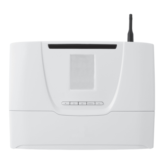
- in a room with a lot of dust or with a corrosive atmosphere. Scope of delivery 1 5 0 2 packs with 2 screws with Ø 6 mm plugs 2 packs containing 7 anti-tamper connectors (one anti-tamper connector installed) Control unit 0020094626_00 - 06/10 - Glow-worm - 5 -... -
Page 8: Installation
• Level the control unit (4). • Mark the 2 lower wall attachment points (3), in line with the mounting holes. • Remove the control unit (4) by sliding along the wall. 0020094626_00 - 06/10 - Glow-worm - 6 -... -
Page 9: Electrical Connections
The RJ9 EBUS (4) socket is used for diagnosing the appliance. • Screw the 2 lower attachment screws (1) to attach the The RJ11 EBUS (5) socket is used for connecting the EBUS control unit to the wall. extension board. 0020094626_00 - 06/10 - Glow-worm - 7 -... -
Page 10: Internal Connection
OUT1, OUT2, OUT3, IN2, IN3, NTC1, NTC2, NTC3 and NTC4 EBUS connectors (2 pins) 230 V power cable Break out tab Consult the system manual for electrical connections Anti-tamper connection following installation. Power connection Control unit 0020094626_00 - 06/10 - Glow-worm - 8 -... -
Page 11: Commissioning
Switch On (I) / Off (O) • Turn on the control unit (1) with the switch (2) in position (I). When connected for the fi rst time, the installation menu is displayed. 0020094626_00 - 06/10 - Glow-worm - 9 -... -
Page 12: Installation Menu
Pairing (recognition) is necessary in order to use: - the Climapro RF room thermostat(s), - the wireless outdoor sensor. The control units installation menu allows you to carry out certain adjustments to the installation. 0020094626_00 - 06/10 - Glow-worm - 10 -... -
Page 13: Automatic Test
• Carry out the necessary wiring work. The wireless outdoor sensor must be paired with Once the power has been reconnected, the control unit returns the Systempro control before installing the outdoor to the current control function. sensor. • Repeat the test. -
Page 14: Parameters
The fault status may be “inactive” (disappeared) "active" (still affects the installation). Consult the system manual in order to install and - resetting the fault report. start-up the system. 0020094626_00 - 06/10 - Glow-worm - 12 -... -
Page 15: Options
The resetting of factory settings is irreversible. Any customised confi guration of the control unit will be lost. • Simultaneously press the buttons for 10 seconds. • Confi rm by pressing 0020094626_00 - 06/10 - Glow-worm - 13 -... -
Page 16: Maintenance
- "After sales service Info", in the options. 13.2.1 Access to the maintenance menu • Press the “menu” button for 7 seconds. • Enter the installer maintenance access code 35. • Press the button to confi rm. 0020094626_00 - 06/10 - Glow-worm - 14 -... -
Page 17: System Failure Codes
Failure in communication with the wireless The wireless outdoor sensor is too far Check that the sensor’s power supply is outdoor sensor from the control unit. correctly provided by a photovoltaic cell. 0020094626_00 - 06/10 - Glow-worm - 15 -... -
Page 18: Control Unit Failures
• Replace the fuse following the order (A) to (F). • Slightly turn the control unit (2) fuse holder (4) using a screwdriver. • Remove the fuse holder (4) and the fuse (1). 0020094626_00 - 06/10 - Glow-worm - 16 -... - Page 20 Because of our constant endeavour for improvement, details may vary slightly from those shown in these instructions. Glow-worm, Nottingham Road, Belper, Derbyshire. DE56 1JT...
Need help?
Do you have a question about the SYSTEMPRO and is the answer not in the manual?
Questions and answers