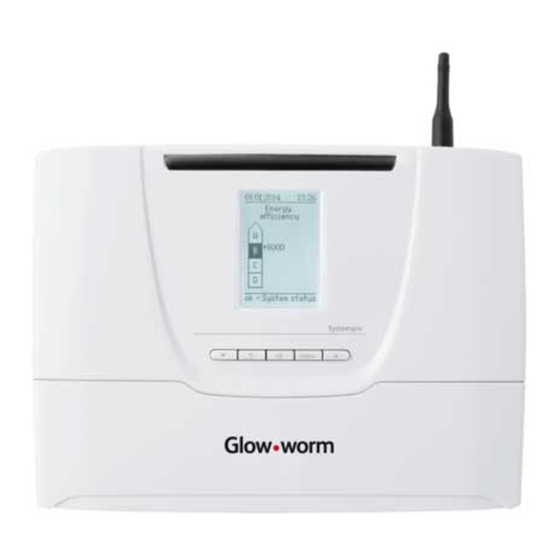
Glow-worm SYSTEMPRO Instructions For Use Manual
Heating controller
Hide thumbs
Also See for SYSTEMPRO:
- Installation and servicing (20 pages) ,
- Homeowner's manual (2 pages)
Table of Contents
Advertisement
Advertisement
Table of Contents

Summary of Contents for Glow-worm SYSTEMPRO
- Page 1 The energy you need Instructions for use Installation and Servicing SYSTEMPRO...
- Page 2 Description and operation of the product ..................3 Recycling and disposal ......................... 4 Recycle the packaging ......................4 Recycle or dispose the product and its components ...............4 Guarantee and customer service ....................4 0020148679_00 - 11/12 - Glow-worm - 2 -...
-
Page 3: Notes On The Documentation
Risk due to changes in the surroundings of the product Certain home improvements may adversely aff ect the operation of your product. ∙ Consult your installer for advice before carrying out any work. 0020148679_00 - 11/12 - Glow-worm - 3 -... -
Page 4: Recycling And Disposal
∙ Make sure the old unit and any accessories are disposed of properly. ∙ Observe all relevant regulations. Guarantee and customer service ∙ For information and manufacturer's guarantee, contact the address given on the back of the instructions. 0020148679_00 - 11/12 - Glow-worm - 4 -... -
Page 5: Table Of Contents
Recycle the packaging ......................15 Recycle or dispose the product and its components .............15 Technical data ..........................15 Appendix ........................... 16 10.1 Table of menus and functions .....................16 10.2 Table of system failure codes .....................17 0020148679_00 - 11/12 - Glow-worm - 5 -... -
Page 6: Notes On The Documentation
Applicability of the instructions These installation instructions are only valid for boilers with the following article numbers: Type overview Product Article number SYSTEMPRO 0020128489 0020148679_00 - 11/12 - Glow-worm - 6 -... -
Page 7: Intended Use
- European Directive Num. 2006-95 of the European Parliament and the Council regarding low voltage - Directive regarding telecommunications equipment ( Directive R & TTE 99/5/EEC of the Council of the European Community) 0020148679_00 - 11/12 - Glow-worm - 7 -... -
Page 8: Product Description
- To access the installation menu. - To access the maintenance menu. - To return to the installation and maintenance menus (at any time). - To return to the main user screen by pressing for 3 seconds. 0020148679_00 - 11/12 - Glow-worm - 8 -... -
Page 9: Mounting And Installation
- above a cooking device capable of generating steam and Upper attachment holes grease, - in a room with a lot of dust or with a corrosive atmosphere. 2 9 0 1 5 0 2 6 4 0020148679_00 - 11/12 - Glow-worm - 9 -... - Page 10 ∙ Attach the appliance (B). Hatch screw Control unit hatch Lower attachment holes Control unit Upper attachment holes Upper screw Plug Holes ∙ Position the appliance following the steps from (A) to (E). 0020148679_00 - 11/12 - Glow-worm - 10 -...
-
Page 11: Electrical Installation
Electrical wires Outside wireless temperature sensor Casing Room thermostat eBUS wireless or wired Batteries ∙ Maintain a maximum distance of 20 mm between the Wired outdoor sensor connector and the outer insulation. 0020148679_00 - 11/12 - Glow-worm - 11 -... - Page 12 Connectors (3 pins: earth / neutral / live): REL1, REL2 and REL3 Connectors (2 pins: live / neutral): REL4, REL5 and IN1 The connector (1) is employed to connect the electricity supply. 0020148679_00 - 11/12 - Glow-worm - 12 -...
-
Page 13: Commissioning
230 V power cable Break out tab Anti-tamper connection Power connection Control unit eBUS ∙ Connect the control unit following the order (A) to (D). 0020148679_00 - 11/12 - Glow-worm - 13 -... -
Page 14: System Failure Codes
By entering the test menu, the control unit displays the following message: “the system is currently stopped" No further heating control operations are aff ected. Control is resumed upon exiting the menus. 0020148679_00 - 11/12 - Glow-worm - 14 -... -
Page 15: Replacing A Fuse
∙ Do not dispose of your product or any of its accessories in the household waste. ∙ Make sure the old unit and any accessories are disposed of properly. ∙ Observe all relevant regulations. 0020148679_00 - 11/12 - Glow-worm - 15 -... -
Page 16: 10 Appendix
Convector fan start conditions Cold water outlet temperature setting Fixed convector fan start setting Humidity sensor Cold water outlet calculation mode setting (fi xed or variable) Off set (Epsilon) Circulation pump purge setting 0020148679_00 - 11/12 - Glow-worm - 16 -... -
Page 17: Table Of System Failure Codes
Failure in communication with the wireless The wireless outdoor sensor is too far from the correctly provided by a photovoltaic cell. outdoor sensor control unit. The outside sensor has no battery to be replaced. 0020148679_00 - 11/12 - Glow-worm - 17 -... - Page 20 Supplier / Manufacturer GLOW-WORM Nottingham Road, Because of our constant endeavour for Belper, Derbyshire. improvement, details may vary slightly DE56 1JT from those shown in these instructions. The energy you need www.glow-worm.co.uk...


Need help?
Do you have a question about the SYSTEMPRO and is the answer not in the manual?
Questions and answers