Marantz RC9500 Service Manual
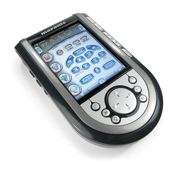
Touch screen remote control
Hide thumbs
Also See for RC9500:
- User manual (78 pages) ,
- Specifications (1 page) ,
- Full line catalog (39 pages)
Advertisement
Quick Links
Download this manual
See also:
User Manual
Service
Manual
REMARK :
• MODEL No:RC9500/F S
AC
Please use this service manual with referring to the user guide ( D.F.U. ) without fail.
Printed on 100% Recycled Paper
Printed in Japan
Touch Screen Remote Control
4-2
8-1
RC9500
RC9500 /
PM-14SAAF N
RC9500
Part no. 90M32BW855010
F S
(SA14/F1N)
First Issue 2004.11
MJI
Advertisement

Related Manuals for Marantz RC9500


Summary of Contents for Marantz RC9500
- Page 1 PM-14SAAF N (SA14/F1N) Manual Touch Screen Remote Control REMARK : • MODEL No:RC9500/F S RC9500 Please use this service manual with referring to the user guide ( D.F.U. ) without fail. RC9500 Printed on 100% Recycled Paper Part no. 90M32BW855010 First Issue 2004.11...
- Page 2 製品仕様 ディスプレイ 6,4000色3.8インチTFTタッチスクリーンLCD 解像度:320×240ピクセル(QVGA) LCD用バックライト:白色LED/ボタン用:青色LED インターフェイス パソコン接続用:USB1.1ポート 赤外線 (IR) 発光用LED:4個/受光用LED:1個 到達可能距離:約10m 学習可能キャリア周波数:78kHz以下および455kHz 内蔵メモリ 16MB不揮発性フラッシュメモリ 電源 ニッケル水素 (NiMH) 充電池(RC9500専用) 外形寸法 153mm(奥行き)×90mm(幅)×33.5mm(高さ) 重量 約250g(充電池含む) 動作温度 摂氏5∼45度 付属品 パソコン接続用USBケーブル ニッケル水素 (NiMH) 充電池 4.8V ドッキングステーションDS9500(充電器) ドッキングステーション用電源アダプタ この仕様または外観を改善のため予告なく変更することがあります。 RC9500のリセット方法 ◆ ◆ RC9500が正常に動作しなくなったとき は、以下の手順でRC9500をリセットして ください。 RC9500の充電池ケースカバーを取...
- Page 3 HOME THEATER Control Panel RC9500 /A1T/N1M/T1M/U1G TS9500 DS9500 Service Manual TABLE OF CONTENTS Page Mechanical Instructions ............. Electrical diagrams ..............Mainboard component layout ........... Mechanical & Electrical Parts list ..........Mechanical Instructions - Docking station ......... Electrical diagrams - Docking station ........
- Page 4 MECHANICAL INSTRUCTIONS - TS9500 Set Disassembly 1. Remove battery lid 2. Remove battery 3. Remove 2 x screw (Torx screw 2x6) see picture - arrows 4. Put a sharp knife between toppart and bottompart and use this as lever to separate the two parts. see picture Overview snapholes...
- Page 5 MECHANICAL INSTRUCTIONS - TS9500 Disassembly LCD & Buttons Fig. 2 1. Remove 5 x screw (Torx screw 2x6 ). see fig.1 - arrows 2. Fig.2 arrow A: Release flex cable lock in direction arrow C and remove flex 3 Fig.2 arrow B: Turn cable lock 90 degree and remove flex 4.
- Page 6 MECHANICAL INSTRUCTIONS - TS9500 Set Reassembly 1. Put Toppart (*item1) and IR-wind assy (*item 4) together. 1 + 4 2. Place Toppart assy (item1 & item4) upside down. 3. Place LCD assy. (*item15) 4. Place action keys assy . (*item8) 5.
- Page 7 ELECTRICAL DIAGRAM 0101 J4 3917 F 16 0102 J5 3918 F 17 0103 J5 6101 J9 Main Section 0104 J3 6102 I 10 0105 J3 6103 H12 0106 J4 6104 K10 0107 J4 7101 E 5 DATA(0:15) DATA(0:15) 0108 J5 7102-1 C12 Touch{X_Right,X_Left,Y_Top,Y_Bot} 0109 J5...
- Page 8 ELECTRICAL DIAGRAM 0002 A16 0003 A16 1201 B16 LCD- Controller 1202 J16 1203 C9 2201 H11 2202 H12 2203 H3 2204 H3 0002 0003 2205 H3 LCD{FD(2:7),FD(10:15),FD(18:23)} 7213-1 2206 H3 MQ1178GCC 2207 H3 Φ 2208 I 3 -9V1_LCD +3V3_LCD ENVDD EN_VDD FLAT 2209 K7...
- Page 9 ELECTRICAL DIAGRAM G1 F 10 5302 B14 U2 A13 5303 C15 0304 B2 5304 D14 Power Circuits 1301 C4 5305 E 12 1302 F 2 5306 F 4 1304 I 2 5307 H14 1305 I 5 6301 C5 2301 C2 6302 J5 +3V3 VBATT...
- Page 10 ELECTRICAL DIAGRAM G3 K7 U1 H8 1401 C3 IR-RF-Circuit 1402 C10 2401 C9 2402 C13 2404 E 2 2405 H8 2406 H8 2407 I 10 2408 I 12 2409 I 13 2410 H13 2411 E 15 2412 D6 +3V3 VBATT 2413 E 6 2414 D3 7401-D...
- Page 11 COMPONENT LAYOUT SIDE-A VIEW Assembly A-Side 3104 207 5034 bl132-1 dd4-05-04...
- Page 12 COMPONENT LAYOUT SIDE-B VIEW Assembly B-Side 3104 207 5034 bl132-2 dd4-05-04...
-
Page 13: Exploded View
EXPLODED VIEW 1001... -
Page 14: Usb Cable
90M32BW158010 WINDOW IR-WINDOW + BEZEL ASSY 3104 207 80862 90M32BW270010 BUTTON SIDE BUTTONS ASSY 3104 207 80872 90M32BW104010 RETAINER DOC PLUG INSERT - RC9500 3104 204 20971 90M32BW270020 BUTTON ACTION KEYS ASSY 3104 207 80891 90M32BW270030 BUTTON LOWER KEYMAT ASSY... - Page 15 DOCKING STATION DS9500...
-
Page 16: Mechanical Instructions
MECHANICAL INSTRUCTIONS Set Disassembly - Docking station 1. Remove the four rubber feet 2. Remove 4 x screw see picture - arrows Overview snapholes 3. Put a sharp knife between toppart and bottom part and use this as lever to separate the two parts. For the correct position of the knife see snapholes in picture Overview disassembled parts... - Page 17 CHARGER DIAGRAM 1001 E 11 1002 F 3 1003 F 3 2001 F 3 2002 F 3 2003 C10 2004 D4 2005 D6 2006 C8 2007 C5 2008 B7 3001 B8 BATPLUS 3002 A3 3003 B7 3004 B3 3005 C8 POWER 3006 C2 3007 C2...
- Page 18 LED BOARD DIAGRAM & Component Layout CHARGE BOARD - Component Layout DEVICE DOCKING 1002 1001 85595-001 SLW..R BATMINUS BATPLUS BATPLUS GND_PRONTO1 GND_PRONTO1 GND_PRONTO1 GND_PRONTO2 POWER -THERM BATMINUS VBAT -THERM CONTROL GND_PRONTO2 POWER VBAT 6001 6002 3104 207 5026 bl130 dd23-05-03 TLHB4201 TLHB4201 Component Layout...
-
Page 19: Docking Station
MECHANICAL & ELECTRICAL PARTS LIST - Docking Station DS9500 20 DOCKING STATION 21 PWB ASSY SERV CON DS5400 VERS. PART NO. PART NO. POS. NO. PART NAME DESCRIPTION COLOR (FOR EUR) (MJI) DOCKING STATION PARTS LIST 2422 086 11101 90M-FS001230R FUSE FUSE SMT 750MA 125V 1003 90M-ZK000470R UNIT KIT...
Need help?
Do you have a question about the RC9500 and is the answer not in the manual?
Questions and answers