Table of Contents
Advertisement
Quick Links
SERVICE MANUAL
Ver 1.0 2003. 07
SPECIFICATIONS
Frequency range
FM: 87.5 – 108 MHz
AM: 530 – 1,710 kHz
Power requirements
3 V DC batteries R6 (AA) × 2/External DC 3 V power sources
Dimensions
91.4 × 115.5 × 35.9 mm (3
× 4
5/8
5/8
projecting parts and controls
Mass
Approx. 150 g (5.3 oz.)
Approx. 230 g (8.2 oz.) incl.batteries and a tape
Supplied accessories
Stereo headphones or Stereo earphones (1)
Design and specifications are subject to change without
notice.
Sony Corporation
9-961-044-01
2003G04-1
Personal Audio Company
© 2003. 07
Published by Sony Engineering Corporation
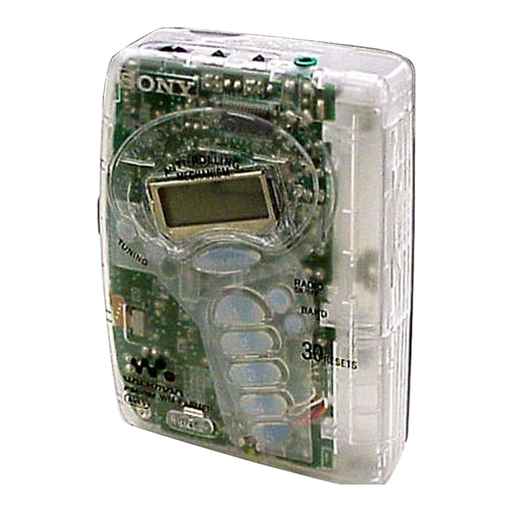
WM-FX271FP
× 1
inches) (w/h/d) incl.
7/16
Model Name Using Similar Mechanism
Tape Transport Mechanism Type
Notes on Chip Component Replacement
• Never reuse a disconnected chip component.
• Notice that the minus side of a tantalum capacitor may be dam-
aged by heat.
Flexible Circuit Board Repairing
• Keep the temperature of the soldering iron around 270°C during
repairing.
• Do not touch the soldering iron on the same conductor of the
circuit board (within 3 times).
• Be careful not to apply force on the conductor when soldering
or unsoldering.
RADIO CASSETTE PLAYER
US Model
WM-FX271
MF-WMFX171-114
1
Advertisement
Table of Contents

Related Manuals for Sony WM-FX271FP


Summary of Contents for Sony WM-FX271FP
- Page 1 • Do not touch the soldering iron on the same conductor of the circuit board (within 3 times). • Be careful not to apply force on the conductor when soldering or unsoldering. RADIO CASSETTE PLAYER Sony Corporation 9-961-044-01 2003G04-1 Personal Audio Company © 2003. 07 Published by Sony Engineering Corporation...
-
Page 2: Table Of Contents
WM-FX271FP UNLEADED SOLDER TABLE OF CONTENTS Boards requiring use of unleaded solder are printed with the lead free mark (LF) indicating the solder contains no lead. 1. GENERAL ................3 (Caution: Some printed circuit boards may not come printed with the lead free mark due to their particular size.) -
Page 3: General
WM-FX271FP SECTION 1 GENERAL This section is extracted from instruction manual. Location of parts and controls NORM/CrO /METAL AVLS DX/LOCAL or VOLUME NORM/CrO /METAL ST/FM MONO x STOP MEGA BASS RADIO ON/OFF NPLAY BAND mREW 1-5 (preset) TUNING +/– HOLD DC IN 3V * The button has a tactile dot. -
Page 4: Disassembly
WM-FX271FP SECTION 2 DISASSEMBLY • The equipment can be removed using the following procedure. Cabinet (front) sub assy Main board Holder (sub) assy, cassette Belt and Motor Mechanism deck Note : Follow the disassembly procedure in the numerical order given. -
Page 5: Main Board
WM-FX271FP 2-2. MAIN BOARD 3 screw (M1.4), toothed lock (WH) 2 Unsolder the 4 places. 5 MAIN board 1 HEAD FLEXIBLE board (CN301) 4 two claws 2-3. HOLDER (SUB) ASSY, CASSETTE 2 Insert a precision screwdriver (1.4 mm flat-blade) vertically into portion A to release the hinge plate. -
Page 6: Mechanism Deck
WM-FX271FP 2-4. MECHANISM DECK 2 Remove the mechanism deck in the direction of the arrow. 1 Insert the precision screwdriver (1.4 mm flat-blade) into the slit and release three claws. 2-5. BELT AND MOTOR 2 two screws (screw (M1.4), toothed lock) 3 motor •... -
Page 7: Mechanical Adjustments
WM-FX271FP SECTION 3 SECTION 4 MECHANICAL ADJUSTMENTS ELECTRICAL ADJUSTMENTS PRECAUTION PRECAUTION 1. Clean the following parts with a denatured-alcohol-moistened • Supplied voltage : 2.5V swab : • Switch and control position playback head pinch lever assy VOLUME control : maximum... -
Page 8: Tuner Section
WM-FX271FP TUNER SECTION 0 dB = 1 µV • AM Section Setting: • FM Section RADIO ON/OFF switch: ON Setting: BAND switch : AM RADIO ON/OFF switch: ON BAND switch : FM AM Tuning Voltage Adjustment FM Tuning Voltage Adjustment... - Page 9 WM-FX271FP Adjustment Location: main board AM IF ADJUSTMENT AM TUNING VOLTAGE ADJUSTMENT AM TRACKING ADJUSTMENT FM TUNING VOLTAGE ADJUSTMENT FM TRACKING ADJUSTMENT Measurement Points: main board (FM RF IN) (VT) FM RF IN...
-
Page 10: Diagrams
WM-FX271FP SECTION 5 DIAGRAMS 5-1. IC PIN DESCRIPTION • IC701 µPD17072GB-559-1A7 (SYSTEM CONTROL/LCD DRIVE) Pin No. Pin Name Pin Description INIT Initialize output 2, 3 — Not used. MEGA BASS MEGA BASS ON/OFF output (L: ON, H: OFF) RADIO-ON Radio circuit power control output 6 –... -
Page 11: Block Diagram
WM-FX271FP 5-2. BLOCK DIAGRAM HP901 FM/AM RF, IF, MPX PLAYBACK AUDIO POWER AMP HEAD IC301(1/2) S303-2 FWD IN(L) B.P.F FM IN L OUT REV IN(L) FM/AM MIX – LOCAL R-CH 10.7MHz VOLUME FM IF R OUT R CH IN(L) RV301-1... -
Page 12: Printed Wiring Board
WM-FX271FP 5-3. PRINTED WIRING BOARD : Uses unleaded solder. • Semiconductor Location Ref. No. Location D301 D302 D303 (FM RF IN) D701 F-10 IC301 H-11 IC701 F-11 IC702 F-13 D-10 Q101 H-12 Q201 H-12 Q301 D-10 Q302 Q303 (VT) Q304... -
Page 13: Schematic Diagram
WM-FX271FP 5-4. SCHEMATIC DIAGRAM • Refer to page 14 for IC Block Diagrams and page 14 for Note on Schematic Diagram. R712 S713 R710 S715 S707 S714 JR707 R706 S708 S706 S705 R715 R703 R707 Q703 JR704 S702 S701 S704... - Page 14 WM-FX271FP Note for schematic diagram: • IC Block Diagrams • All capacitors are in µF unless otherwise noted. pF: µµF IC1 TA2111F 50 WV or less are not indicated except for electrolytics and tantalums. • All resistors are in Ω and W or less unless otherwise specified.
-
Page 15: Exploded Views
WM-FX271FP SECTION 6 EXPLODED VIEWS NOTE: • The mechanical parts with no reference • Color Indication of Appearance Parts number in the exploded views are not supplied. Example : • Items marked “*” are not stocked since KNOB, BALANCE (WHITE) ... (RED) they are seldom required for routine service. -
Page 16: Tape Mechanism Section-1
WM-FX271FP 6-2. TAPE MECHANISM SECTION-1 (MF-WMFX171-114) HP901 M901 Ref. No. Part No. Description Remark Ref. No. Part No. Description Remark 3-013-560-11 BELT 3-704-197-71 SCREW (M1.4X4.5), LOCKING 3-238-876-04 SCREW (M1.4), TOOTHED LOCK HP901 1-500-532-11 HEAD, MAGNETIC (PLAYBACK) X-3378-976-1 LEVER (NL) ASSY, PINCH... -
Page 17: Tape Mechanism Section-2
WM-FX271FP 6-3. TAPE MECHANISM SECTION-2 (MF-WMFX171-114) not supplied not supplied not supplied not supplied Ref. No. Part No. Description Remark Ref. No. Part No. Description Remark 3-921-797-01 WASHER 3-921-335-03 WASHER, LEVER X-3376-206-1 CHASSIS (COMP) ASSY (GL-02) 3-921-042-01 GEAR (REEL) X-3372-619-3 WHEEL ASSY (NP), CAPSTAN... -
Page 18: Electrical Parts List
WM-FX271FP SECTION 7 MAIN ELECTRICAL PARTS LIST NOTE: • Due to standardization, replacements in • Items marked “*” are not stocked since When indicating parts by reference the parts list may be different from the they are seldom required for routine service. - Page 19 WM-FX271FP MAIN Ref. No. Part No. Description Remark Ref. No. Part No. Description Remark C707 1-162-920-11 CERAMIC CHIP 27PF L302 1-414-760-21 INDUCTOR, FERRITE BEAD C708 1-162-917-11 CERAMIC CHIP 15PF L304 1-414-760-21 INDUCTOR, FERRITE BEAD C709 1-107-826-11 CERAMIC CHIP 0.1uF L701...
- Page 20 WM-FX271FP MAIN Ref. No. Part No. Description Remark Ref. No. Part No. Description Remark R301 1-216-821-11 METAL CHIP 1/10W < TRANSFORMER > R302 1-216-837-11 METAL CHIP 1/10W R303 1-218-867-11 METAL CHIP 6.8K 1/10W 1-406-694-11 COIL, AM IFT R304 1-216-823-11 METAL CHIP 1.5K...
- Page 21 WM-FX271FP MEMO...
- Page 22 WM-FX271FP REVISION HISTORY Clicking the version allows you to jump to the revised page. Also, clicking the version at the upper on the revised page allows you to jump to the next revised page. Ver. Date Description of Revision 2003. 07...
Need help?
Do you have a question about the WM-FX271FP and is the answer not in the manual?
Questions and answers