Sony WM-FX277 Service Manual
Hide thumbs
Also See for WM-FX277:
- Service manual (24 pages) ,
- Operating instructions (2 pages) ,
- Service manual (22 pages)
Table of Contents
Advertisement
WM-FX277/FX467/FX467ST
SERVICE MANUAL
Ver 1.0 2000.03
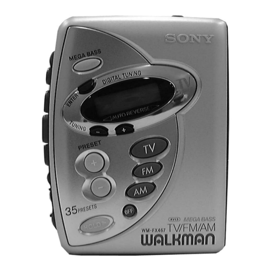
Photo : WM-FX467
SPECIFICATIONS
• Frequency range
FM: 87.5 - 108 MHz
AM: 530 - 1,710 kHz
TV: 2 - 13 ch
• Power requirements
3V DC batteries R6 (AA) x 2
• Dimensions (w/h/d)
Approx. 91.4 x 115.5 x 35.0 mm (3
incl. projecting parts and controls
• Mass
FX467/FX467ST: Approx. 155 g (5.5 oz)/Approx. 235 g (8.3 oz) incl.
batteries and a cassette
FX277: Approx. 145 g (5.2 oz)/Approx. 225 g (8.0 oz) incl. batteries
and a cassette
• Supplied accessories
Stereo headphones or Stereo earphones (1)
Carrying case with belt clip(1)
Design and specifications are subject to change without notice.
Battery life (approximate hours)
Sony alkaline LR6 (SG)
Tape playback
25
Radio reception
40
* Measured value by the standard of EIAJ (Electronic Industries
Association of Japan). (Using a Sony HF series cassette tape)
Note
• The battery life may shorten depending on the operation of the unit.
Model Name Using
NEW
Mechanism Type
Similar Mechanism
WM-FX277
Tape Transport
WM-FX467/FX467ST : MF-WMFX467-114
5
5
7
x 4
x 1
⁄
⁄
⁄
inches)
8
8
16
(EIAJ*)
Sony R6P (SR)
7.5
14
RADIO CASSETTE PLAYER
US Model
: MF-WMFX277-114
Advertisement
Table of Contents

Related Manuals for Sony WM-FX277


Summary of Contents for Sony WM-FX277
- Page 1 Tape playback Radio reception * Measured value by the standard of EIAJ (Electronic Industries Association of Japan). (Using a Sony HF series cassette tape) Note • The battery life may shorten depending on the operation of the unit. RADIO CASSETTE PLAYER...
-
Page 2: Table Of Contents
4-2. Block Diagram ............10 4-3. Printed Wiring Boards ..........13 4-4. Schematic Diagram ........... 17 5. EXPLODED VIEWS 5-1. Cabinet Section ............21 5-2. Mechanism Deck Section (WM-FX277) ....22 5-3. Mechanism Deck Section (WM-FX467/FX467ST) ........... 23 6. ELECTRICAL PARTS LIST ........24... -
Page 3: Disassembly
SECTION 2 DISASSEMBLY The equipment can be removed using the following procedure. Cabinet (Front) Main board Mechanism deck Belt, Capstan/reel motor (M601) Cassette holder Note : Follow the disassembly procedure in the numerical order given. 2-1. CABINET (FRONT) Cassette holder Cabinet (center) sub ASSY 3 Claws 1 Claws... -
Page 4: Mechanism Deck
2-3. MECHANISM DECK Mechanism deck 1 Claws Cabinet (center) sub ASSY 2-4. BELT, CAPSTAN/REEL MOTOR (M601) 3 Screws (M1.4) 4 Capstan/reel motor Mechanism deck (M601) • How to apply the belt Capstan/reel motor (M601) Belt 1 Claw wheel ASSY (P), capstan (FX467/FX467ST) wheel ASSY (P), capstan 2 Belt... -
Page 5: Cassette Holder
2-5. CASSETTE HOLDER 2 Move the hinge away from projection Hinge Projection 3 Move the hinge away from projection Hinge Cabinet (center) sub ASSY Projection Hinge Hinge 4 Spring (torsion) Cassette holder CAUTIONS DURING ASSEMBLY Insert the spring (torsion) to the L shape slot as shown in the figure. 2,3 Insert the hinge of the “Cassette holder ”. -
Page 6: Adjustments
SECTION 3 ADJUSTMENTS 3-1. MECHANICAL ADJUSTMENTS 3-2. ELECTRICAL ADJUSTMENTS PRECAUTION PRECAUTION 1. Clean the following parts with a denatured-alcohol-moistened • Supplied voltage : 2.5V. swab : • Switch and control position playback head pinch roller MEGA BASS : OFF capstan rubber belt VOLUME control : maximum 2. - Page 7 • Repeat the procedures in each adjustment several times, and the TUNER SECTION 0 dB = 1µ V frequency coverage and tracking adjustments should be finally AM Section done by the trimmer capacitors. BAND : AM AM IF ADJUSTMENT AM RF signal Put the lead-wire Adjust for a maximum reading on level meter.
- Page 8 FM VCO Adjustment FM RF signal Procedure : generator 0.01µF (FM/TV IN) Carrier frequency : 98MHz Modulation : No modulation [MAIN BOARD] Output level : 0.1V (100dB/ µV) (Side B) 1. Connect the frequency counter as shown in the figure. 2.
-
Page 9: Diagrams
WM-FX277/FX467/FX467ST 4-2. BLOCK DIAGRAM SECTION 4 DIAGRAMS 4-1. EXPLANATION OF IC TERMINALS IC702 LC72348W-CFX1705 SYSTEM CONTROL Pin No. Pin name Descliption XOUT Crystal oscillator output (75kHz). TEST2 – Not used (Ground). Key input. Key input. Key input. Key input. Key output. - Page 10 WM-FX277/FX467/FX467ST 4-3. PRINTED WIRING BOARDS Semiconductor Location DRY BATTERY Ref. No. Location SIZE "AA" (IEC DESIGNATION R6) 2PCS, 3V C-18 D-18 [MAIN BOARD] (SIDE B) [MAIN BOARD] (SIDE A) D-18 D401 D402 D703 B-10 C-18 IC301 E-14 J301 IC701 E-15...
-
Page 11: Schematic Diagram
WM-FX277/FX467/FX467ST 4-4. SCHEMATIC DIAGRAM Refer to page 20 for IC Block Diagrams. Waveforms 425 mVp-p 75 kHz IC702 1 VOLT/DIV : 0.1 V AC XOUT TIME/DIV : 5 µsec 1.8 Vp-p 319 nsec VOLT/DIV : 0.5 V AC Q401 C TIME/DIV : 0.1 µsec... -
Page 12: Exploded Views
NOTE : • -XX, -X mean standardized parts, so they • The mechanical parts with no reference 5-2. MECHANISM DECK SECTION (WM-FX277) 48 47 46 45 44 43 may have some difference from the original number in the exploded views are not one. -
Page 13: Mechanism Deck Section (Wm-Fx467/Fx467St)
5-3. MECHANISM DECK SECTION (WM-FX467/FX467ST) (MF-WMFX467-114) supplied supplied not supplied supplied supplied supplied M601 HP601 Ref. No. Part No. Description Remark Ref. No. Part No. Description Remark X-3369-749-1 PINCH LEVER (N) ASSY 3-923-530-01 SLEEVE (M) 3-920-996-01 SPRING (PINCH N) 3-728-091-01 WASHER, STOPPER X-3372-619-1 WHEEL ASSY (P), CAPSTAN 3-921-052-11 LEVER (A), DETECTION (FX467,FX467ST) 3-704-197-71 SCREW (M1.4) (FX467,FX467ST) -
Page 14: Electrical Parts List
SECTION 6 MAIN ELECTRICAL PARTS LIST NOTE : • Due to standardization, replacements in the • Items marked “ * ”are not stocked since they When indicating parts by reference num- parts list may be different from the parts are seldom required for routine service. Some ber, please include the board. - Page 15 MAIN Ref. No. Part No. Description Remark Ref. No. Part No. Description Remark C710 1-117-863-11 CERAMIC CHIP 0.47uF 6.3V < RESISTOR > C711 1-104-847-11 TANTAL. CHIP 22uF C712 1-126-916-11 ELECT 1000uF 6.3V 1-216-825-11 METAL CHIP 2.2K 1/16W C714 1-162-964-11 CERAMIC CHIP 0.001uF 1-216-817-11 METAL CHIP 1/16W...
- Page 16 WM-FX277/FX467/FX467ST MAIN Ref. No. Part No. Description Remark Ref. No. Part No. Description Remark R706 1-216-845-11 METAL CHIP 100K 1/16W ACCESSORIES & PACKING MATERIALS R707 1-216-845-11 METAL CHIP 100K 1/16W ******************************** R708 1-216-849-11 METAL CHIP 220K 1/16W R710 1-216-833-91 RES-CHIP...
Need help?
Do you have a question about the WM-FX277 and is the answer not in the manual?
Questions and answers