Sony WM-FX267 Service Manual
Hide thumbs
Also See for WM-FX267:
- Operating instructions (2 pages) ,
- Operating instructions manual (8 pages)
Advertisement
SERVICE MANUAL
Ver 1.3 2000. 05
With SUPPLEMENT-1
(9-923-300-81)
With SUPPLEMENT-2
(9-923-300-82)
MICROFILM
WM-FX267/FX269
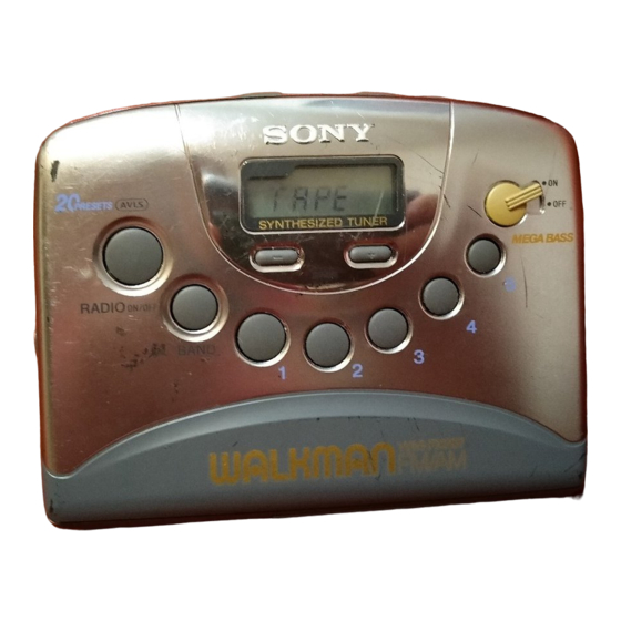
Photo: WM-FX267 US model
SPECIFICATIONS
• Frequency range
FM: 87.5-108MHz
AM: 530-1710kHz (US)
AM: 531-1602kHz (EXCEPT US)
• Power requirements
3V DC batteries AA (R6) × 2/External DC 3V
power sources
• Demensions
115 × 90.5 × 34.4mm (4
5
/
8
incl. projecting parts and controls
• Mass
Approx. 150g (5.3 oz)
Approx. 230g (8.2 oz) incl. batteries and a tape
• Supplied accessories
Stereo headphones or earphones (1)
Carrying case (1)
Design and specifications are subject to change without notice.
Model Name Using Similar Mechanism
Tape Transport Mechanism Type
× 3
5
/
1
3
/
inches) (w/h/d)
8
8
RADIO CASSETTE PLAYER
US Model
WM-FX267/FX269
AEP Model
E Model
WM-FX267
WM-FX251
MF-WMFX251-114
Advertisement
Table of Contents

Related Manuals for Sony WM-FX267


Summary of Contents for Sony WM-FX267
- Page 1 WM-FX267/FX269 Ver 1.3 2000. 05 AEP Model With SUPPLEMENT-1 E Model (9-923-300-81) WM-FX267 With SUPPLEMENT-2 (9-923-300-82) Photo: WM-FX267 US model Model Name Using Similar Mechanism WM-FX251 Tape Transport Mechanism Type MF-WMFX251-114 SPECIFICATIONS • Frequency range FM: 87.5-108MHz AM: 530-1710kHz (US) AM: 531-1602kHz (EXCEPT US) •...
-
Page 2: Table Of Contents
TABLE OF CONTENTS SERVICING NOTES GENERAL ..............3 HOW TO CHANGE THE CERAMIC FILTERS This model is used two ceramic filters of CF2 and X2. DISASSEMBLY You must used same type of color marked ceramic filters in order ............6 to meet same specifications. -
Page 3: General
SECTION 1 This section is extracted from instruction manual. GENERAL – 3 –... - Page 4 – 4 –...
- Page 5 – 5 –...
-
Page 6: Disassembly
SECTION 2 DISASSEMBLY • This set can be disassembled in the order shown below. MAIN BOARD BELT, CABINET (FRONT) ASS’Y MECHANISM DECK (Page 7) MOTOR (REEL/CAPSTAN) (Page 6) (MF-WMFX251-114) (M901) (Page 8) (Page 8) CASSETTE HOLDER (Page 7) Note: Follow the disassembly procedure in the numerical order given. CABINET (FRONT) ASS’Y 1 Insert the precision screwdriver (1.4 mm flat-blade) in to the slit... - Page 7 MAIN BOARD 3 screw (M1.4) 5 MAIN board 2 Removal the four solders. 4 two claws 1 flexible board (CN301) CASSETTE HOLDER 2 Insert a precision screwdriver (1.4 mm flat-blade) vertically in to portion A to release the hinge plate. 3 Portion B to release the hinge plate.
- Page 8 MECHANISM DECK (MF-WMFX251-114) 2 Remove the mechanism deck (MF-WMFX251-114) in the direction of the arrow A . 1 Insert the precision screwdriver (1.4 mm flat-blade) in the slit and relese two claws. BELT, MOTOR (REEL /CAPSTAN) (M901) 2 two screws 3 motor (reel/capstan) (M1.4 ×...
-
Page 9: Mechanical Adjustments
SECTION 4 SECTION 3 ELECTRICAL ADJUSTMENTS MECHANICAL ADJUSTMENTS Precaution Precaution 1. Clean the following parts with a denatured-alcoholmoistened • Supplied voltage: 2.5 V swab: • Switch and control position playback head pinch roller TAPE switch: NORM capstan rubber belt RADIO switch : ST (AEP and French models) 2. -
Page 10: Tuner Section
AM SECTION TUNER SECTION 0 dB=1 µV Setting: FM SECTION RADIO ON/OFF switch: ON BAND switch: AM Setting: RADIO ON/OFF switch: ON AM Tuning Voltage Adjustment BAND switch: FM FM Tuning Voltage Adjustment digital voltmeter MAIN board digital voltmeter (VT) MAIN board –... - Page 11 Adjustment Location: [MAIN BOARD] – Component Side – Tape Speed Adjustment AM Tuning Voltage Adjustment RV601 FM Tracking Adjustment (FM RF IN) IC401 IC301 (GND) C401 AM IF Adjustment (VT) FM Tuning Voltage Adjustment AM Tracking Adjustment [MAIN BOARD] – Conductor Side – (FM RF IN) (GND) (VT)
-
Page 12: Diagrams
SECTION 5 DIAGRAMS 5-1. IC PIN FUNCTION DESCRIPTION • MAIN BOARD IC401 µPD17015GS-545-GJG-E1 (SYSTEM CONTROLLER, LCD DRIVER) Pin No. Pin Name Function KEYIN3 Key return signal input terminal KEYOUT1 KEYOUT2 Key strobe signal output terminal KEYOUT3 MUTE Muting on/off control signal output to the LA4582CM (IC301) “L”: muting on BEEP/INIT Buzzer sound drive signal output terminal Station detector detect signal input from the TA2111F (IC1) SD is present at input of “L”... -
Page 16: Schematic Diagram
• Waveforms 1 IC401 !£ (XIN) 3 Q307 (COLLECTOR) 500 mV/DIV, 5µs/DIV 500 mV/DIV, 100 ns/DIV 1.5 Vp-p 2 Vp-p 75.2 kHz 3.38 MHz 2 T301 (SECONDARY) 4 Q307 (BASE) 5 V/DIV, 200 ns/DIV 100 mV/DIV, 100 ns/DIV 0.3 Vp-p 20.6 Vp-p 2.53 MHz 3.38 MHz... - Page 17 • IC Block Diagrams IC1 TA2111F-(EL) IC601 LB1979V-TLM – 23 –...
-
Page 18: Exploded Views
SECTION 6 EXPLODED VIEWS NOTE: • -XX and -X mean standardized parts, so they • Items marked “*” are not stocked since they may have some difference from the original are seldom required for routine service. Some one. delay should be anticipated when ordering •... - Page 19 (2) MAIN SECTION-2 MF-WMFX251-114 LCD401 Ref. No. Part No. Description Remark Ref. No. Part No. Description Remark 3-015-285-01 SCREW (M1.4),TOOTHED LOCK (WH) 3-007-010-01 TERMINAL (–), BATTERY A-3016-995-A MAIN BOARD, COMPLETE (FX267: US) 3-007-006-11 BUTTON (STOP) (p) A-3016-996-A MAIN BOARD, COMPLETE (FX267: AEP) 3-007-004-11 BUTTON (FF) ()) A-3016-997-A MAIN BOARD, COMPLETE (FX267: 2CE7) 3-007-003-11 BUTTON (PLAY) (()
- Page 20 (3) MECHANISM DECK SECTION (MF-WMFX251-114) HP901 M901 Ref. No. Part No. Description Remark Ref. No. Part No. Description Remark 3-013-560-11 BELT 3-703-816-31 SCREW (M1.4), SPECIAL HEAD X-3372-959-1 CHASSIS COMP ASSY (GL-O) X-3369-747-1 WHEEL ASSY, CAPSTAN 3-703-816-73 SCREW (M1.4), SPECIAL HEAD 3-728-091-01 WASHER, STOPPER 3-923-530-01 SLEEVE (M) 3-921-797-01 WASHER...
-
Page 21: Electrical Parts List
SECTION 7 MAIN ELECTRICAL PARTS LIST NOTE: • Due to standardization, replacements in the • Items marked “*” are not stocked since they When indicating parts by reference number, please include the board. are seldom required for routine service. parts list may be different from the parts speci- fied in the diagrams or the components used Some delay should be anticipated when order- •... - Page 22 MAIN Ref. No. Part No. Description Remark Ref. No. Part No. Description Remark C326 1-115-156-11 CERAMIC CHIP D303 8-719-801-78 DIODE 1SS184 C327 1-164-156-11 CERAMIC CHIP 0.1uF D402 8-719-801-78 DIODE 1SS184 (FX267: AEP, 2CE7, FR) C329 1-162-953-11 CERAMIC CHIP 100PF < IC > C330 1-165-176-11 CERAMIC CHIP 0.047uF...
- Page 23 MAIN Ref. No. Part No. Description Remark Ref. No. Part No. Description Remark Q401 8-729-422-27 TRANSISTOR 2SD601A-Q R208 1-216-839-11 METAL CHIP 1/16W Q402 8-729-422-27 TRANSISTOR 2SD601A-Q (FX267: AEP, E) Q403 8-729-102-27 TRANSISTOR 2SC2223-T1F12 R208 1-216-847-11 METAL CHIP 150K 1/16W Q405 8-729-901-46 TRANSISTOR DTA114YK (FX269) R208...
- Page 24 WM-FX267/FX269 MAIN Ref. No. Part No. Description Remark < SWITCH > S301 1-762-742-31 SWITCH, DETECTION (SMALL TYPE) (TAPE POWER) S303 1-692-298-11 SWITCH, SLIDE (NORM·CrO2/METAL) S305 1-692-298-11 SWITCH, SLIDE (AVLS) S306 1-572-922-11 SWITCH, SLIDE (MEGA BASS) < TRANSFORMER > 1-406-694-11 COIL, AM IFT...
- Page 25 WM-FX267/FX269 US Model WM-FX267/FX269 AEP Model SERVICE MANUAL E Model WM-FX267 1998. 08 SUPPLEMENT-1 File this supplement with the service manual. Subject: Change of motor (M901) (ENG-98005) Mounting shape to the mechanism deck and to the exterior cabinet is not compatible.
- Page 26 Addition of Mexican Model Mexican Model have been added. They are the same as FX267 (E) model which is not described in this supplement-2. Refer to WM-FX267/FX269 original service manual (9-923-300-S) for other information. ACCESSORIES & PACKING MATERIAL Page FX267: E model FX267: Mexican model Ref.
Need help?
Do you have a question about the WM-FX267 and is the answer not in the manual?
Questions and answers