Risco Agility Installer Manual
Hide thumbs
Also See for Agility:
- Software manual (56 pages) ,
- User manual (52 pages) ,
- Manual (4 pages)
Table of Contents
Advertisement
Quick Links
Download this manual
See also:
User Manual
Advertisement
Table of Contents

Related Manuals for Risco Agility


Summary of Contents for Risco Agility
- Page 1 Installer Manual ...
-
Page 2: Important Notice
Agility Installer Manual Important Notice This guide is delivered subject to the following conditions and restrictions: This guide contains proprietary information belonging to RISCO Group. Such information is supplied solely for the purpose of assisting explicitly and properly authorized users of the system. No part of its contents may be used for any other purpose, disclosed to any person or firm, or reproduced by any means, electronic or mechanical, without the express prior written permission of RISCO Group. The information contained herein is for the purpose of illustration and reference only. Information in this document is subject to change without notice. Corporate and individual names and data used in examples herein belong to their respective owners. Compliance Statement Hereby, RISCO Group declares that the Agility series of central units and accessories are designed to comply with: EN50131‐1, EN50131‐3 Grade 2 EN50130‐5 Environmental class II EN50131‐6 Type A UK: DD243:2004, PD 6662:2004, ACPO (Police) USA: FCC: Part 15B, FCC part 68 CANADA: CS‐03, DC‐01 All rights reserved. © 2008 RISCO Group December 2008 Page ii... -
Page 3: Table Of Contents
CHAPTER 1 INTRODUCTION ................1-1 ......................1-2 RCHITECTURE ......................1-3 AIN EATURES ..................1-4 ECHNICAL PECIFICATIONS CHAPTER 2 INSTALLING THE AGILITY ............2-1 ..................2-1 GILITY AIN OMPONENTS ..................... 2-2 OUNTING THE GILITY Choosing the mounting location................2-2 Wall Mounting the Agility..................2-2 ... - Page 4 Agility Installer Manual CHAPTER 4 INSTALLER MENUS................4-1 ................4-1 SING THE GILITY KEYPAD KEYS ................4-2 CCESSING THE NSTALLER ENUS ....................4-2 ROGRAMMING 1. Programming: System Menu ................4-2 1.1 Timers ...........................4-3 1.2 Controls ........................4-5 1.3 Labels ..........................4-13 1.4 Sounds ........................4-15 1.5 Settings........................4-15 1.6 Service Information....................4-16 ...
- Page 5 Agility Installer Manual 7. IP Unit........................ 4-71 8. UO Unit ......................4-72 ...................... 4-72 CTIVITIES ....................4-73 OLLOW E ......................4-73 LOCK ..................... 4-73 VENT OG APPENDIX A REPORT CODES ................A‐1 APPENDIX B INSTALLER EVENT LOG MESSAGES ........B‐1 APPENDIX C LIBRARY VOICE MESSAGES............C‐1 APPENDIX D EN 50131 COMPLIANCE ..............D‐1 ...
- Page 6 Agility Installer Manual Page vi...
-
Page 7: Chapter 1 Introduction
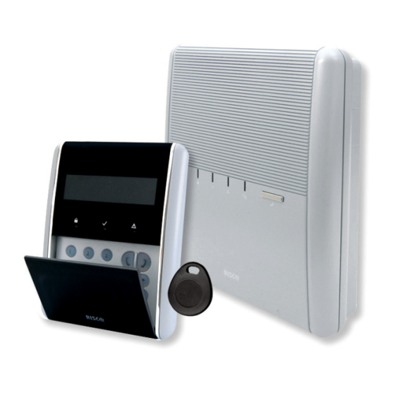
Agility Installer Manual Chapter 1 Introduction The Agility is a Flexible Wireless Security Solution that incorporates state‐of‐the‐art wireless and communication technology. Agility is ideal for installation in any home or office environment and supports RISCO Group’s extensive range of one‐way and two‐way wireless security and safety devices, keypads, remote controls, keyfobs, panic buttons, fully wireless sirens and other accessories. Main Benefits: Flexible Plug‐in Communication IP Module GSM/GPRS Module Fast PSTN Module Use any single module, any combination or all three modules for backup, or no communication for audible only installations 2‐Way Wireless Keypad with full programming capability 2‐Way 8 button Wireless Remote Control with code protection, key‐lock and system status request and indication 2‐way voice communication Easy enrolling of Wireless Devices without any keypad Remote enrolling according to Device ID Combine one–way or two‐way transmitters in the same system Flash memory for easy firmware upgrade Simple physical installation with wall brackets Separate main panel, can be hidden for higher security Program Transfer Module (PTM) for program backup Simplified menu logic (only menus of installed devices are displayed, only menus according to the authorization code are displayed) Main Features: 32 wireless zones 3 partitions Up to 3 bi‐directional wireless keypads Up to 8 Remote Control keyfobs (combination of 8 or 4 button) or one way Input/Output module: 2‐way wireless communication to the Agility Local transformer with rechargeable backup batteries 4 wired zones with selectable EOL resistance & 4 outputs (2x3A relay and 2x500mA) Includes X‐10 adaptor ... -
Page 8: Architecture
Agility Installer Manual Architecture The following diagram provides an overview of the Agilityʹs architecture and capabilities. Examine the figure before beginning with your Agility installation to obtain an overall picture of the full extent of the Agility system capabilities. Page 1-2... -
Page 9: Main Features
Agility Installer Manual Main Features The following illustration describes the main features of the Agility: Detectors Monitoring Station Communication: Installer Programming: • 32 Wireless zones: • Remote programming, • Flexible communication • Local /Remote using • 4 Wired zones via diagnostics and over GSM/GPRS, IP or configuration software • Program transfer optional Wireless I/O communication test. PSTN. • Report to 3 MS. • Backup capability Expander module. • Total zones: 36 • Report thought PSTN, • Full programming using ... -
Page 10: Technical Specifications
Agility Installer Manual Technical Specifications The following technical specifications are applicable for the Agility: Electrical Characteristics Power 230VAC (‐15%+10%), 50Hz, 50mA Units consumptions Main board: Typical 130mA GSM: Stand by 35mA, Communication 300mA Modem: Stand by 20mA, Communication 60mA IP Card: 90mA (Max) Backup battery Sealed Lead Acid Battery 6V 3.3Ah Internal Siren intensity 90 dBA @1m Operating temperature ‐10°C to 40°C (14°F to 131°F) Storage temperature ‐20°C to 60°C (‐4°F to 140°F) Physical Characteristics Dimension 268.5 mm x 219.5 mm x 64 cm (10.57 x 8.64 x 2.52 inch) Weight (no battery) 1.31Kg (Full configuration) GSM module: 0.045 Kg Wireless Characteristics Radio Immunity According to EN 50130‐4 Frequency 868.65 MHz/433.92 MHz Page 1-4... -
Page 11: Chapter 2 Installing The Agility
Agility Installer Manual Chapter 2 Installing the Agility This chapter covers the installation procedures of the Agility, as follows: Agility Main Components, page 2‐1 Mounting the Agility, page 2‐2 Choosing the mounting location, page 2‐2 Wall Mounting the Agility page 2‐2 Connecting the Backup Battery, page 2‐5 Connecting the Agility to Power Supply, page 2‐6 Ground Connection, page 2‐6 DIP switch setting, page 2‐8 Connecting a telephone line to the Agility, page 2‐9 SIM Card Installation, page 2‐9 External Audio Unit, page 2‐12 Agility Main Components The illustration below shows the internal components (when the Mounting Bracket is disassembled from the Back Panel). Configuration A Configuration B Figure 1: Agility Main Components 1. Installation Bracket 7. Transformer 13 RS 232 communication connector 2. Telephone Jacks 8. Back Panel ... -
Page 12: Mounting The Agility
Mounting the Agility IMPORTANT: The Agility has no user replaceable parts (for instance: power cord, fuse, battery, etc.) only certified installers are allowed to replace faulty parts. Choosing the mounting location Before you mount the Agility, study the premises carefully in order to choose the exact location of the unit for the best possible coverage and yet easily accessible to prospective users of the alarm system. The mounting location of the Agility should be: Try to centrally locate the system between all the transmitters. Near an uninterrupted AC outlet. Near a telephone outlet. Far from sources of interference, such as: Direct heat sources Electrical noise such as computers, televisions etc. Large metal objects, which may shield the antenna. In a place where the alarm can be heard during Part Arming mode. Wall Mounting the Agility The Agility is comprised of two sub‐assemblies: Mounting bracket, Main unit which in its turn is comprised from: Front panel (not disassembled on a regular installation procedure) Back panel The mounting bracket is mounted on the wall, using the supplied proper hardware, as described below: To mount the Agility on the Wall: Separate the Mounting bracket as follows: Release the Mounting bracket captive locking screws (1, Figure 2) located at the bottom of the unit by turning screws counterclockwise. Figure 2: Mounting Bracket screws Page 2-2... - Page 13 Agility Installer Manual Gently, pull up the Mounting bracket to a 45° angle and slide it down to release the Mounting bracket (2, Figure 3) from the two locking tabs (1, Figure 3) at the top of the unit. Note: Do not open the Mounting bracket to a larger angle in order not to break the two top tabs and not to tear up the ribbon flat cable connecting the power supply unit to the front panel (PCB). Disconnect the ribbon flat cable (3) from the power supply unit while leaving it connected to the Main panel. Figure 3: Mounting Bracket removal Hold the Mounting bracket against the wall as a template and mark the locations for the mounting holes (5 mounting holes item 1, and an additional hole for securing the tamper protection bracket item 2, are available, see Figure 4). Drill the desired mounting holes and place the screw anchors. Use the supplied 5 Philips pan head screws to attach the Mounting bracket to the wall (ST4.2 mm x 32 mm DIN 7981). According to the location of the wall cables, route and insert the wires and cables via the cable’s openings (3) (including AC cable and telephone cable), see figure 3. If required, remove cable knockouts (5) to allow wire passage. Anchor cables with dedicated hooks (4). Page 2-3...
- Page 14 Agility Installer Manual Configuration A Configuration B Figure 4: Wall Installation Adjust the Tamper switch (using a flat screwdriver) according to your preferred configuration. Box and Wall configuration (see Figure 4, detail 6) ‐ Triggers the tamper when the box or the wall mounting are tampered. Box only configuration (see Figure 4, detail 7) – Triggers the tamper when the box is tampered. Page 2-4...
-
Page 15: Connecting The Backup Battery
Agility Installer Manual Connecting the Backup Battery The Agility has safety approved, sealed lead acid 6V, 3.3Ah rechargeable backup battery used in time of main power failure: Note: The battery is not supplied with the Agility To insert the Backup battery: Remove the battery compartment cover screw (see Figure 5,3) located at the top of the cover by turning screw counterclockwise and pull the Agility battery cover outward. Figure 5: Battery Compartment a. Insert the battery into its place and connect the flying leads to the battery according to the correct polarity (Red +) (Black ‐). b. Return the battery compartment cover (after placing the battery in) and secure with locking screw. Note: The Agility Rechargeable battery should be charged for at least 24 hours. Important: When replacing the battery be sure to buy the same type. Failure to comply with this instruction may result in damage to personnel and/or equipment. Dispose of used batteries according to the proper instructions. Page 2-5... -
Page 16: Ground Connection
Agility Installer Manual Connecting the Agility to Power Supply - Configuration A Note: The Agility panel is permanently connected to the mains. The connection must be made according to your countryʹs local regulations. As a general guideline, connect the Live Neutral and Ground using a safety approved 3‐wire 18AWG power cable (14‐mm minimum diameter flexible PVC cable which complies with IEC60227). The cable should be brought to the Agility panel in a protective plastic conduit (diameter ‐ 16mm minimum). A 2‐pole 16A circuit breaker and earth leakage protector should be used to disconnect the live conductor, and should be provided as part of the building installation. The Agility is powered by a safety approved 230VAC. 1. Remove the power supply unit cover (Figure 6, 1). 2. Connect the power wire (Safety approved, SVT, 18AWG, 0.75mm ) to the power terminal located on the power supply unit (TB1) (2, Figure 6). Note: The power wire is not supplied with the Agility 3. DO NOT connect the cable to the wall power supply at this point. Ground Connection Grounding provides a degree of protection against lightning and induced transients for any piece of electronic equipment that may, due to lightning or static discharge, experience permanent or general malfunctions. The ideal ground is considered to be a unified earth ground in which an 8‐foot copper‐clad rod, located close to the existing power and telephone ground rods, is sunk several feet into the earth. Appropriate hardware and clamps are then used to electrically connect each of these rods together and then to the ground terminal of the device to be protected. It may be possible to use an existing electrical ground on the premises if one is close enough to the Agility. When connecting the ground wire, use a solid 14‐gauge wire [or larger (numerically lower) size]. Keep this wire as short as possible and do not run it in conduit, coil it, bend it sharply, or run it alongside other wiring. If you must bend it or ... - Page 17 Agility Installer Manual Figure 6: Connecting AC Power wires Connecting the Agility to Power Supply - Configuration B The Agility is powered by a 9VDC/1.0A Transformer. Connect the transformer power jack to the power supply located on the power supply card (1, Figure 6A). DO NOT connect the transformer inlet cable to the wall power supply at this point. From 9VDC/1.0A Transformer Figure 6A: Connecting DC Power Cable Page 2-7...
-
Page 18: Completing Installation
Agility Installer Manual Completing Installation 1. Set the DIP Switches according to the DIP Switch Setting section (see page 2‐8). 2. Connect the ribbon flat cable between the main panel and the mounting bracket (J1). 3. Mount the Main unit to the mounting bracket using captive locking screws. 4. Plug in the power cable to the wall power outlet. 5. Power up the Agility. DIP switch setting Factory Default DIP Switch 1 (E‐A): External Audio: Used to define if the voice of the Agility will go from the main unit or from an External Audio Unit. When the external unit is connected to the Agility the voice will be heard only through the Audio voice unit. ON: External Audio Unit is connected to the Agility OFF (Default): External Audio unit not connected to the Agility. DIP Switch 2 (DFLT): Default jumper: Used when performing the following 3 operations: 1. To return installer, sub‐installer and grand master codes to their default factory values. Set this DIP switch to ON, disconnect all power and then reconnect the power. 2. To manually erase wireless devices. Set this DIP switch to ON while power is connected. Execute a long press on the main unit button until a beep, indicating that all wireless devices have been erased, is heard. 3. To save or transfer data to or from the PTM device. ON: To transfer data from the PTM to the panel. OFF: To transfer data from the panel to the PTM. (Refer to Chapter 3 for these procedures.) DIP Switch 3 (PRGM): Enables loading local software updates to the Agility ON: software updates to the Agility can be loaded ... - Page 19 Agility Installer Manual Connecting a telephone line to the Agility Connect the system to a telephone line if the system configuration includes an internal modem (identical for Configuration A and B). 1. Connect the incoming telephone line to the plug‐in CONN2 jack RJ11 (pins 2, 3) or to plug‐in CONN3 RJ31 (pins 4, 5) (see Figure 7: Telephone Line Jacks). Connect any telephone on the premises to the plug‐in CONN2 jack RJ11 (pins 1, 4) or to plug‐in CONN3 RJ31 (pins 1, 8) (see Figure 7: Telephone Line Jacks). NOTE: To ensure line seizure capability, and comply with FCC part 68 regulations, the equipment must be connected directly to the Phone company lines (ʹCOʹ). Whether connected via RJ11, RJ31, the line port must be connected to the CO lines without any other phones or other telecom equipment between them. Other telecom equipment can be connected only after (in series) the alarm panel. CONN2 RJ11 CONN3 RJ31 Figure 7: Telephone Line Jacks Page 2-9...
- Page 20 Agility Installer Manual Connecting a network cable to the Agility If your Agility is equipped with an IP Card, you should connect the incoming network cable in order to enable IP Communication. 1. Separate the Agility from the mounting bracket. 2. According to the location of the network cable, route and insert the cable via the cable’s openings (see figure 3). 3. If required, remove cable knockouts (5, Figure 3) to allow cable passage. 4. Connect the incoming network cable to the plug‐in. Page 2-10...
-
Page 21: Sim Card Installation
Insert SIM card card hatch . hatch . Slide up to lock. into dedicated slot. Figure 8: SIM Card Insertion Important: Do not install SIM card while power is applied to the Agility. Do not touch SIM Card connectors! If doing so, you may release an electrical discharge that could damage the SIM card. 2. If a PIN code is required for the SIM card, the Agility will indicate a PIN code trouble. To fix the trouble, and thus enable the SIM card to operate properly, enter the PIN code number, located in the Communication > GSM parameters menu. Note: Ensure that you have the PIN code. Be aware that after three wrong attempts (recognized by the SIM card) to enter a PIN number, the SIM card will lock. You will have to contact your local cellular provider to unlock the SIM card. 3. If you want to disable the SIM PIN code you should follow the steps: a. Insert the SIM card into a standard GSM mobile phone. b. Insert the PIN code. c. Access the phone security menu and selecting PIN OFF. Once done, re‐test by switching the phone OFF, then switching ON. The PIN code should not be requested again. ... -
Page 22: External Audio Unit
Agility Installer Manual External Audio Unit The Agility enables to connect an external Audio Unit instead of the internal unit in order to listen to the systemʹs audio messages in a distance from the main unit. In addition the unit enables you to talk into your premises. To connect the Audio unit: Wire the Audio unit to the Agility as displayed in the Wiring Diagram described in Figure 9. The terminals for wiring the Audio Unit to the Agility are located on mounting bracket the Agility. Set DIP Switch 1 (E‐ A) (External Audio) to On position. Audio Unit Terminals on the External Audio Unit Mounting Bracket TMP GND AUX MIC SPKR AUDIO Figure 9: Wiring the External Audio Unit to Agility Page 2-12... -
Page 23: Chapter 3 Installer Programming
Agility Installer Manual Chapter 3 Installer Programming Programming Methods There are 4 available options for programming the Agility: Configuration Software Wireless Keypad Installer Keypad PTM Configuration Software A software application that enables you to program the Agility from a PC computer. It offers the following alternatives: Working locally, through a portable computer connected to the Agility via cable Working at a remote site, communicating with the Agility via a phone line, modem or IP address. For further information on programming the Agility via the Configuration software, refer to the Agility Configuration Software manual. Wireless Keypad The Agility can be fully configured via the wireless keypad. Notes: 1. The Agility can be programmed via any of the 2 way keypads in your system, but only using one keypad at a time for programming. 2. During installer programming, the keypad will turn off after 4 minutes if no entry has been made to the keys. Press any button to restore the keypad. It will display the last parameter you were working on. To program the Agility via the Wireless Keypad, follow this procedure: Perform system device allocation for the keypad (refer to page 3‐4). Press and enter the installer code (default code is 0132). The keypad will sound a confirmation sound. Note: If a Grand Master code is required to confirm the installer code, it should be entered at this stage after the installer code. Go to the Programming menu and press . Once the panel is in programming ... -
Page 24: Installer Keypad
Agility Installer Manual Note: The installer can also program user activities by selecting the Activities menu instead of the Programming menu. Use the buttons to navigate between the menus. Installer Keypad For those systems that do not have keypads, RISCO Group offers the Agility installer a temporary keypad to be used as any Agility wireless keypad for configuring a system. An hour after exiting the programming mode the Installer Keypad will be erased from the Agility memory or when power is lost to the system. To program the Agility via the Installer Keypad, follow this procedure: To allocate the Installer Keypad into the system perform a short press on the main unit button. Press the buttons on the keypad simultaneously until the following confirmation message is heard: “Installer Keypad Allocated”. Follow steps 2 and 3 of the wireless keypad (see page 3‐1) to begin programming the system. PTM: Data Storing Device The PTM is a tiny circuit board into which the Agility panel can transmit a copy of the systemʹs configuration. The PTM stores this copy and can also transmit the configuration information back to the Agility panel. To transfer the system configuration from the panel to the PTM, follow this procedure: Disconnect the flat cable and remove the Agility main unit from its wall bracket. Note: Make sure the battery is inserted into the main unit. Make sure that Dipswitch 2 is set to OFF (default setting). Place the PTM onto the 5‐pin PTM located on the rear of the main unit PCB. The PTM LED will turn on. Press the main unit button for 5 seconds. The PTM LED will flash quickly during the transmission of information to the PTM. Once transmission is complete, the panel will sound a confirmation beep and the PTM LED will stop flashing and turn on steady. Disconnect the PTM from the main unit. Reconnect the flat cable to the main unit and replace the main unit in its wall bracket. Page 3-2... - Page 25 Agility Installer Manual To transfer the system configuration from the PTM to the Agility panel, follow this procedure: Disconnect the flat cable and remove the Agility main unit from its wall bracket. Note: Make sure the battery is inserted into the main unit. Make sure that the Default Enable system flag is on Set Dipswitch 2 to ON. Place the PTM onto the 5‐pin PTM connector located on the main unit PCB. All LEDS on the main unit will begin to flash simultaneously. The PTM LED will flash quickly during the transmission of information to the panel. Once transmission is complete, the panel will sound a confirmation beep. Note: If the procedure fails the panel will make 3 short error beeps, and you will need to do the procedure again Disconnect the PTM from the main unit. Reset Dipswitch 2 to OFF. Reconnect the flat cable to the main unit and replace the main unit in its wall bracket. Page 3-3...
-
Page 26: Wireless Device Allocation
Agility Installer Manual Wireless Device Allocation Each wireless device must identify itself to the system receiver. The following section describes the different ways to allocate all of your devices to the system in order to later configure each deviceʹs parameters The learning procedure between you’re the wireless devices and the main unit can be performed either from the main unit, a wirless keypad or via the Configuration Software. Quick Allocation using the main unit button To perform quick allocation using the main unit button, follow this procedure: Note: . To enable Quick Allocation mode the System bit ʺQuick Learnʺ should be enabled Set the main unit to Learn mode with a long press on the main unit button. Each LED will light up one after another. Note: The unit will sound each time you enter or exit the Learn mode. Send a transmission from each device (refer to the Transmitters write message method table in section). The system will automatically identify each device according to different categories (for example: detectors, sirens, keypads, remote controls etc.) and enter each device and its default value into the unitʹs memory. Each device receives an index number from the system. Exit the Learn mode with a short press on the main unit button. Allocation using the keypad It is possible to perform allocation via the keypad in two different ways: RF Allocation or by entering the device’s serial code. To perform RF Allocation via the keypad, follow this procedure: Go to the Installer menus and select Programming Radio Device Allocation ... -
Page 27: Allocation Using The Configuration Software
Agility Installer Manual Allocation using the Configuration Software It is possible to perform wireless device allocation via the configuration software in two different ways: RF Allocation or by entering the device’s serial code . To perform RF allocation from the configuration software Establish Communication between the main unit and the Configuration software. (For more information refer to the Configuration Software Manual) Open the Activities > Radio Device Allocation screen. Click on the button. This operation will set the main unit to Learn mode. The following message appears: Send a transmission from the device. (See table below) The main unit will acknowledge the transmission with a sound. When the system recognizes the device the Radio Device Allocation screen indicates that the status of allocation has been successful. The serial number, accessory type and the index number information will be displayed. The index number is automatically addressed by the system. Note: If required you can change the index number of the wireless device by selecting the required index number and pressing the button again. To allocate an other wireless device click on the button and then repeat stages 3‐7. To perform Code allocation from the configuration software Establish Communication between the main unit and the Configuration software by selecting Communication>Connect from the main menu. (For more information refer to the Configuration Software Manual) Open the Radio Device Allocation screen. In the Allocation area, enter the deviceʹs serial number. Note: The serial number can be found on the device itself and on its packaging. Select the wireless device index number. Automatic means that the index number ... -
Page 28: Transmitters Write Message Method
Agility Installer Manual The main unit will acknowledge the transmission with a sound. When the system recognizes the device the Radio Device Allocation screen indicates that the status of allocation has been successful. Transmitters Write Message Method How to send a write message (transmission): Wireless Device Sending Write Message Detector/Contacts Press the tamper switch for 3 seconds 2‐Way Keypad Press both keys and simultaneously for at least 2 seconds 1‐Way Keypad Press the key twice 1‐Way Key fob Press the button for at least 2 seconds 2‐Way Remote Control Press both keys and ... -
Page 29: Deleting Wireless Accessories
Agility Installer Manual Deleting Wireless Accessories Deleting all wireless devices can be done manually (from the main unit) or from the Configuration software. To manually delete all wireless accessories from the system: Place Dip Switch 2 to ON position. Press the main unit button until it sounds. Replace Dip Switch 2 to OFF position. To delete a wireless accessory from the Wireless Keypad Go to the Installer menus and select Programming Radio Device Modification Select the device category Go to Parameters option. Select the device index number Go to Serial number option and type in 000000000000. Press . The device will be deleted To delete a wireless accessory from the system via the Configuration software: Establish Communication between the main unit and the Configuration software (For more information refer to the Configuration Software Manual) In the Radio Device Allocation screen in the Delete Accessories area enter the deviceʹs serial code and click the Delete button. To delete all wireless accessories from the system via the Configuration software: Establish Communication between the main unit and the Configuration software by selecting Communication>Connect from the main menu. (For more information refer to the Configuration Software Manual) In the Radio Device Allocation screen in the Delete Accessories area, click the Delete All button. When all accessories have been deleted the screen will indicate that deletion has been successful. ... - Page 30 Agility Installer Manual Page 3-8...
-
Page 31: Chapter 4 Installer Menus
Agility Installer Manual Chapter 4 Installer Menus The following chapter describes the parameters and programming options of the system and radio devices. These parameters can be programmed via the Agility keypad or the configuration software by the installer. Note: A note appears next to the parameters that can only be programmed via the configuration software. For more information regarding the installation and use of the configuration software refer to the Configuration Software manual. Using the Agility keypad keys The Agility two way keypad contains three LED indicators, an LCD display and a variety of keys. The following table describes the typical uses of the keys when in programming mode. Keys Description The numerical keys on the keypad are used as quick keys, a numerical sequence used as a shortcut to program an option. To program the system using Quick keys: 1. Access the installer menus (see below) and select the relevant main menu option. 2. Press the quick keys in sequence to locate the parameter and press . Numerical keys are also used to input the numeric codes that may be required for arming, disarming, or used to activate specific functions. Exits from the current menu and returns to Normal Operation mode Terminates commands and confirms data to be stored Used to browse through the menu: Scrolls up a list or moves the cursor ... -
Page 32: Accessing The Installer Menus
Agility Installer Manual Accessing the Installer Menus To access the installer menus via the Agility keypad, follow this procedure: Press the key to activate the keypad. Enter the installer code 0132 (default code). Note: If the Authorize Installer system bit is defined as YES, a Grand Master code is required to authorize the installer to enter the programming mode. In this case the Grand Master code should be entered after the installer code via the Grand Master menu Activities Authorize Installer. The following menu appears displaying a list of all the installer menus: Programming Testing Activities Follow Me Clock Event Log Using the keys to select the options. Programming Menu All the system parameters are programmed by the installer via the programming menu. After accessing the installer menus, select the 1) Programming option. The following list appears: 1. System 2. Radio Devices 3. Codes 4. Communication 5. Audio 6. Exit 1. Programming: System Menu The System menu provides access to parameters that are used for programming ... -
Page 33: Timers
Agility Installer Manual 5. Settings 6. Service Information 1.1 Timers The Timers menu contains parameters that specify the duration of an action. System: Timers Parameter Default Range Exit/Entry Delay 1 The amount of time before the system is armed/disarmed. Usually used on front entrance door. Entry Delay 1 30 sec 0‐255 sec Duration of entry delay 1 before the system is disarmed Exit Delay 1 45 sec 0‐255 sec Duration of exit delay 1 before the system is armed Exit/Entry Delay 2 The amount of time before the system is armed/disarmed. Usually used to back door. Entry Delay 2 45 sec 0‐255 sec Duration of entry delay 2 before the system is disarmed Exit Delay 2 ... - Page 34 Agility Installer Manual System: Timers Parameter Default Range RX Supervision 3 hours 0‐7 hours Specifies how often the system expects to get a signal from the systemʹs transmitters. If a signal from a zone is not received during the specified time the zone will be regarded as lost, the system will send a report code to the monitoring station, and the system status will be ʺNot Readyʺ. Notes: 0 hours disables supervision It is recommended to set the supervision time to a minimum of 3 hours TX Supervision 058 0‐255 min Specifies how often the system generates a supervision request to a bi‐directional wireless device. If any of the accessories does not respond to the request, at least once, during the RX Supervision time, the system will regard the accessory as Lost. Note: The device will generate the supervision message according to the time defined. Important: The RX Supervision time should be higher than the Tx Supervision time in order to eliminate false lost event. Redial Wait 30 sec 30‐60 sec The number of seconds between attempts at redialing the same phone number. Applies to both the MS Retries and FM Retries parameters. Note: Used for both PSTN and GSM. Swinger Limit Shutdown 00 0‐15 times A swinger is a repeated violation of the same zone, often resulting in a nuisance alarm and usually due to a malfunction, an environmental problem, or the incorrect installation of a detector or sensor. ...
-
Page 35: Controls
Agility Installer Manual 1.2 Controls The Control menu contains parameters that control specific system operations. System: Controls Parameter Default Basic programming Quick Arm YES YES: Eliminates the need for a user code when arming (Full or partial) the system by a keypad or 2‐way remote control. NO: A valid user code is required for arming using a keypad or remote control. Allow Bypass YES YES: Permits zone bypassing by authorized system users after entering a valid user code. NO: Zone bypassing is NOT permitted. Quick Status YES YES: A user code is not required before pressing the status key/button on your wireless keypad or bi‐directional remote control. NO: A user code is required to activate the status key. False Code Trouble YES YES: A false code report is sent to the monitoring station after five successive attempts at arming or disarming in which an incorrect user code is entered. No alarm sounds at the premises, but a trouble indication appears. The wireless keypad will be locked for 30 minutes. NO: A local alarm is sounded at the premises. Siren Squawk YES YES: Arming or disarming the system using a remote control, wireless keypad or a key‐ switch produces a brief ʺchirpʺ and activates the strobe as follows: • One chirp indicates the system is armed (also when arming with a keypad). ... - Page 36 Agility Installer Manual System: Controls Parameter Default Buzzer Bell NO YES: If an alarm occurs when the system is armed in the Stay Arm mode, a buzzer sounds for 15 seconds before the sirens operate. NO: An alarm in the Stay Arm mode causes sirens to operate simultaneously. Audible Jamming NO Relates to the Jamming Time parameter. YES: Once the specified time is reached, the system activates the siren and sends a report code to the monitoring station. NO: Once the specified time is reached the sirens do not operate. Exit Beeps at Stay YES Determines whether the system will sound beeps during exit time in Stay Arming. YES: Exit beeps will sound NO: Exit beeps will not sound Forced Device Arming YES YES: Arming a partition, using a remote control or key‐switch can be performed with violated (not ready) zones in the system. Any violated (not ready) zone(s) in the partition will be bypassed automatically. The partition is then ʺforce armed,ʺ and all intact zones are capable of producing an alarm. NO: The partition cannot be armed until all violated (not ready) zones are secured. Arm Pre‐warning YES Related to auto Arm/Disarm operation. YES: For any partition(s) set up for Auto Arming, an audible Exit Delay (warning) countdown will commence 4.25 minutes prior to the automatic Arming. During this period, Exit Delay beeps will be heard. You can enter a valid User Code at any time during the countdown to delay the partitionʹs automatic Arming by 45 minutes. When an ʺAuto‐Armʺ partition is disarmed, as described above, it can no longer be automatically armed during the current day. ...
- Page 37 Agility Installer Manual System: Controls Parameter Default Default Enable YES This option contains parameters that relate to what happens to the Installer, Sub‐Installer and Grand Master codes if the Main Panelʹs DEFAULT Dip Switch 2 is in place when power to the Main Panel is switched off and then on. YES: The Installer, Sub‐Installer and Grand Master codes will return to the original, factory default values. NO: The Installer, Sub‐Installer and Grand Master codes will NOT return to the original, factory default values by an unauthorized user. Main Button: Status‐Y/Talk‐N YES The Agility enables the MS to perform Listen‐In and Talk functions in order to verify a cause of event or to guide someone in distress. The Main Button: Status‐Y/Talk‐N parameter determines the function of the button on the surface of the main unit to enable Listen‐In and Talk. YES: Status button – The system will relay the system status. NO: Service call button – The system dials the Monitoring Station to establish 2‐way communication. Quick Learn YES Enables the button on the surface of the main unit to perform quick allocation of wireless devices. (See Chapter 3 System Device Allocation: Manual Setup) YES: Quick learn mode is enabled. Long press on the main unit button will start Learn mode. The LEDs on the main unit will start flashing one after the other NO: Quick learning mode is disabled. The main unit button is not in Learn mode. Advanced programming Area NO Changes the system operation to Area instead of Partition, which then changes only the operation of a common zone. YES: When selected, the following points are relevant: • A common zone will be armed after any partition is armed. ...
- Page 38 Agility Installer Manual System: Controls Parameter Default Global Follower NO YES: Specifies that all zones (that are programmed to follow an Exit/Entry Delay time) will follow the Exit/Entry Delay time of any armed partition. NO: Specifies that all zones (that are programmed to follow an Entry Delay time) will follow the Entry Delay time of only the partitions to which they are assigned. Summer/Winter NO YES: The system automatically sets its time of day clock one hour ahead in the spring (on the last Sunday in March) and one hour back in the Autumn (on the last Sunday in October). NO: No automatic time accommodation is made. 24 Hour Bypass NO YES: It is possible for the user to bypass a 24‐hour zone. NO: It is not possible for the user to bypass a 24‐hour zone. Technician Tamper NO YES: It is necessary to enter the Installer Code to reset a Tamper alarm. Therefore, resetting a Tamper alarm requires the intervention of the alarm company. However, the system can still be set. NO: Correcting the problem resets a Tamper alarm, requiring no alarm company help. Technician Reset NO YES: It is necessary to enter the Installer Code to reset an alarmed partition after it has been disarmed. This requires the intervention of the alarm company. Note: Before the Ready LED can light all zones within the partition must be secured. NO: Once an alarmed partition is reset the Ready LED lights when all zones are secured. Installer Tamper NO YES: After a Tamper alarm, the system is not ready to arm. This requires the intervention of the alarm company. NO: After a Tamper alarm is restored the system is ready. Low Battery Arm ...
- Page 39 Agility Installer Manual System: Controls Parameter Default Siren Pre‐Alarm NO Specifies if the system will send a pre‐alarm message to the siren while an entry delay starts. YES: The system sends a pre‐alarm signal to the siren at the beginning of the entry delay. If the siren does not receive a cancellation signal from the system at the end of the entry time, the siren goes into alarm. NO: Pre‐Alarm disabled Bell 30/10 NO YES: The sirens cease to sound for 10 seconds after each 30 seconds of operation. NO: The sirens operate without interruption. Fire Alarm Pattern NO YES: During a fire alarm, the sirens produce a pattern of 3 short bursts followed by a brief pause. NO: During a fire alarm, the flow of sounds produced by the siren is a pattern of 2 seconds ON, then 2 seconds OFF. IMQ NO YES: Causes the following parameters to function as follows: Auto Arm Bypass: If there is an open zone during the Auto Arm process, the system will be armed, and a silent alarm will be activated (unless the open zone is closed). A utility output defined as “Auto Arm Alarm” is activated. A utility output defined as “Zone Loss Alarm” is activated NO: Causes the following parameters to function as follows: Auto Arm Bypass: If the Auto Arm programming arms the system and there is an open zone during the auto arm, the system will bypass the open zones and arm the system. A utility output defined as “Auto Arm Alarm” is deactivated. A utility output defined as “Zone Loss Alarm” is deactivated. Disable Incoming Call ...
- Page 40 Agility Installer Manual System: Controls Parameter Default Communication MS Enable YES YES: Enables communication with the Central Station to report alarms, trouble, and supervisory events. NO: No communication with the Central Station is possible. Choose NO for installations that are NOT monitored by a Central Station. Configuration Software Enable YES YES: Enables communication between the alarm company and the system using the Configuration software. This enables modifying an installationʹs configuration, obtaining status information, and issuing Main Panel commands, all from a remote location. NO: Disables communication, as detailed above. FM Enable YES YES: Enables Follow‐Me communication. If both the MS phones and the FM phones are defined, the system will first call the MS phones and then the FM phones. NO: Disables Follow‐Me communication. EN 50131 programming Authorize Installer NO This option limits the Installer and Sub‐installer authorization to access the programming menu. YES: A Grand Master code is required to authorize the installer to enter the programming mode for 1 hour. NO: The Installer does not need an authorization code. Override Trouble YES Specifies if the system/partition can be armed when there is a fault in the system. YES: The system will arm even if there is a fault in the system. NO: When the user starts the arming process and there is a system‐fault, the user must confirm that he is aware of all faults before continuing with the Arming process. ...
- Page 41 Agility Installer Manual System: Controls Parameter Default NO Restore Alarm YES: The user must confirm that he is aware that alarm occurred in the system before rearming the system. The system will be in ʺNot Readyʺ status until he confirms the alarm. This is done via the User menu Activities Advanced Restore Alarm. NO: The user does not need to confirm the alarm before rearming the system. NO Mandatory Event Log YES: Only mandatory events (specified in the EN standard) will be displayed in the Event Log. NO: All the events will be displayed in the Event Log. NO Restore Troubles YES: The user must manually confirm the restoral of each trouble to a normal condition. This is done via the User menu Activities Advanced Restore Troubles. NO: The restoral report of each trouble is automatic . YES Exit Alarm YES: A violated zone outside the exit route will generate an alarm during the exit time. A report to the monitoring station for arming the system is sent at the beginning of the arming procedure. NO: A violated zone outside the exit route will cancel the arming process. A report to the monitoring station is send at the end of a successful arming procedure. Entry Delayed Alarm NO This feature is used to reduce false alarm reports to the MS. YES: The report to the MS and the siren alarm will be delayed for 30 seconds or until the ...
- Page 42 Agility Installer Manual System: Controls Parameter Default NO Attenuation YES: The Agility receiver will be attenuated by 6 dB during the communication test. NO: The Agility receiver works in normal operation mode. DD243 programming YES Bypass Exit/Entry YES: It is possible for the user to bypass an Exit/Entry zone. NO: An Exit/Entry zone cannot be bypassed. NO Entry Disable YES: The alarm confirmation process will be disabled when the entry time starts. NO: The alarm confirmation process will start when the entry time starts. NO Route Disable YES: The panel disables the entry route zones (EX/EN, EX (OP)/EN, followers and Final Exit) from participating in the alarm confirmation process when the entry time starts. Note: Sequential confirmation can still be established from two confirmed zones, located off the entry route. NO: The entry route zones will participate in the alarm confirmation process when the entry time starts. NO Installer Reset Confirmation YES: An installer reset confirmation is required in order to reset the system after a confirmed alarm. The system cannot be armed until an Installer Reset Confirmation is performed. The reset can be done by entering the Anti code or entering the installation mode or by performing a “Installer reset” from the keypad. NO: Any means can be used to arm or disarm the system (keypad, remote phone operation etc.). NO Key Switch Lock YES: Only a Latched Key Switch zone can arm or disarm the system. Note: When the system has more than 1 zone defined as Latch Key Switch, the arm/disarm operation will occur only after all these zones are armed or disarmed. NO: Any means can be used to arm or disarm the system (keypad, remote phone ...
-
Page 43: Labels
Agility Installer Manual System: Controls Parameter Default NO Entry Disarm Determines if the system’s disarming depends on the entry time. YES: A remote control can disarm the system only during the entry time. Note: The system can not be disarmed with a remote control while the system is armed. NO: The system can be disarmed during any time using any disarming device. 1.3 Labels You can rename the labels that identify the system and partitions by changing the default labels (Partition 1, Partition 2 and so on) to, for example, The Jonesʹs, Sales Dept, or Mastr Bedr as appropriate. Labels that can be renamed: System: Labels Parameter Default Range System Security System Any 16 characters Edits the global (system) label Partition 1/2/3 Partitions 1 through 3 Any 16 characters Edits partition labels To rename labels using the keypad keys to produce characters see the table below: Data Sequence 1 ... -
Page 44: Sounds
Agility Installer Manual 1.4 Sounds The Sounds menu contains parameters that enable you to set the sound(s) that will be produced by the system after the following system events: System: Sounds Parameter Default Range Tamper Sound BELL/A BUZZER/D 1 to 6 Sets the sound(s) produced by a Tamper violation according to the following options: Silent Bell (External/Internal siren) Buzzer (main unit) Bell + Buzzer Bell/A Buzzer/D: Bell when system armed, Buzzer when system disarmed Bell/A S/Disarm: Bell when system armed, Silence when system disarmed Local Speaker Alarm Volume Level 5 0‐5 Sets the main unitʹs internal speaker Alarm volume. The volume ranges between 0 (silent) to 5 (Max volume). After setting/changing the volume, sound will be emitted by the internal speaker to enable evaluation of the selected volume level. Local Speaker Squawk Volume Level 5 0‐5 Sets the main unitʹs internal speaker Squawk volume. The volume ranges between 0 (silent) to 5 (Max volume). After setting/changing the volume, sound will be emitted by the internal speaker to enable evaluation of the selected volume level. Exit/Entry Beeps Volume Level 3 0‐5 Determines the volume of the beeps sounded from the main unit during the Exit/Entry times. ... -
Page 45: Service Information
Agility Installer Manual System: Settings Parameter Default Range Erase Wireless Device Erase wireless devices without changing the system current programmed parameters . Language Sets the system language (Email, SMS and keypad language) Standards EN 50131 NO Sets the panel programming options in compliance with EN standards. (See Appendix D) DD243 NO Sets the panel programming options in compliance with DD243 standards. 1.6 Service Information The Service Information menu enables you to insert information accessible to the systemʹs users of the alarm company from whom the service is obtained. System: Service Information Parameter Default Range Name Any 16 characters Enables you to insert and/or edit the name of the alarm company from whom service ... -
Page 46: Modification
Agility Installer Manual 2.2 Modification The modification menu is used to change the values of the parameters configured by the system for each wireless device. The modification menu is divided into the following submenus: 1. Zones 2. Remote Control (Keyfob) 3. Keypads 4. Siren 5. I/O Expander Note: This list varies according to the devices that have been allocated to the system. Only devices that have been allocated can be configured or modified by the installer. 2.2.1 Zones The Zones menu is divided into the following sub‐menus: Parameters Alarm (Sequential) Confirmation Soak Test Zone Crossing (only via the Configuration software) Parameters Note: The parameters displayed, vary according to the type of zones connected to the system. Zones: Parameters Parameter Default Range Label Zone 01/02/03/ … Any characters A label identifies the zone in the system. Up to 16 characters). Serial Number The internal ID number of the zone. Each wireless device has its own unique ID number. Placing ID 00000000000 will delete the zone. Partition The partition (1 to 3) assignment for each zone. ... - Page 47 Agility Installer Manual Zones: Parameters Parameter Default Range Exit/Entry 1 Used for Exit/Entry doors. Violated Exit/Entry zones do not cause an intrusion alarm during the Exit/Entry Delay. If the zone is not secured by the end the delay expires it will trigger an intrusion alarm. To start an arming process, this zone should be secured. When system is armed, this zone starts the entry delay time. Exit/Entry 2 Same as above, except that the Exit/Entry 2 time period applies. Exit(Op)/Entry 1 Used for an Exit/Entry door. This zone behaves as described in the Exit/Entry 1 parameter, shown above, except that, if faulted, the arming process is not prevented. To avoid an intrusion alarm, it must be secured before the expiration of the Exit Delay period. Exit(Op)/Entry 2 Same as above, except that the Exit (Op)/Entry 2 time period applies. Entry Follower Usually assigned to motion detectors and to interior doors protecting the area between the entry door and the system. This zone(s) causes an immediate intrusion alarm when violated unless an Exit/Entry zone was violated first. In this case, Entry Follower zone(s) will ...
- Page 48 Agility Installer Manual Zones: Parameters Parameter Default Range Interior + Exit/Entry 2 Same as the I + Exit/Entry 1 parameter, described above, but the Exit/Entry 2 time period is applicable. Interior + Exit(Op)/Entry 1 Used for an exit/entry door that, for convenience, may be kept open when the system is being armed, as follows: In Away (Full Arm) mode behaves as an Exit (Op)/Entry 1 zone. In Stay mode, the zone will be bypassed. Interior + Exit(Op)/Entry 2 Same as the I + Exit (Op)/Entry 1 parameter, described above, but the Exit/Entry 2 time period is applicable. Interior + Entry Follower Generally used for motion detectors and/or interior doors (for example, foyer), which would have to be violated after entry in order to disarm the system, as follows: In Away (Full Arm) mode behaves as an Entry Follower zone. In Stay mode, the zone will be bypassed. Interior + Intruder (Instant) Usually intended for non‐exit/entry doors, window protection, shock detection and motion detectors. In Away (Full Arm) mode behaves as an Intruder (instant) zone. In Stay mode, the zone is bypassed. ...
- Page 49 Agility Installer Manual Zones: Parameters Parameter Default Range Fire For smoke or other types of fire detectors. This option can also be used for manually triggered panic buttons or pull stations (if permitted), as follows: If violated, it causes an immediate fire alarm, fire report to the monitoring station. Panic Used for external panic buttons and wireless panic transmitters. If violated, an immediate panic alarm is sounded (if the zone sound is not defined as silent or Audible Panic system control is enabled), regardless of the systemʹs state and panic report is send to the monitoring station. An alarm display will not appear on the keypads. Special For external auxiliary emergency alert buttons and wireless auxiliary emergency transmitters. If violated, an immediate auxiliary emergency alarm is sounded, regardless of the systemʹs state and report is sent to the monitoring station. Tamper For tamper detection. This zone operates the same as 24 hours zone, but it has a special reporting code. Water (Flood) For flood or other types of water detectors. This zone operates the same as 24 ...
- Page 50 Agility Installer Manual Zones: Parameters Parameter Default Range Technical This zone operates the same as 24 hours zone, its report code should be manually set according to the relevant detector connected to the zone. Final Exit Zones of this type must be the last detector to be activated on exit or the first detector to be activated on entry. When arming the system, the related partition arms 10 seconds after this zone is closed, or opened and then closed. After it is triggered once, the zone acts as an exit (open)/entry 1 zone. Exit Termination This type of zone is used to avoid a false alarm by acting like an Exit (OP)/Entry zone. When triggered (after arming the system and closing the door or opening the door, arming the system, and closing the door), the systemʹs Exit Delay time period will be shortened to 3 seconds. When you re‐open the door, the entry time restarts. UO Trigger For a device or zone, which if violated at any time triggers a previously programmed Utility Output, capable of activating an external indicator, relay, appliance, and so on. Day Usually assigned to an infrequently used door, such as an emergency door or a ...
- Page 51 Agility Installer Manual Zones: Parameters Parameter Default Range Pulsed Key switch Delayed Used to apply the Exit/Entry Delay 1 parameter to the Pulsed Key Switch zone. Latched Key switch Connect an external SPST latched (non‐momentary) key switch follows: After arming one or more partitions using the key switch and then disarming using the keypad, the related partitions will be disarmed. In order to arm the partition using the key switch again, turn the key to the disarm position and then to the arm position. If a key switch latch is assigned to more than one partition and one of the partitions is armed by using the keypad (the key switch stays in the disarm position), then: ‐ When changing the position of the key switch to the arm position, all the disarmed partitions, which belong to this key switch, will be armed. ‐ When turning the key switch to the disarm position, all the partitions will be disarmed. Latched Key switch Delay Used to apply the Exit/Entry Delay 1 parameter to the latched key switch zone. Sound Contains parameters that enable you to program the sound produced when a system zone triggers an alarm for the time defined under the Bell Time Out parameter. Silent ...
- Page 52 Agility Installer Manual Zones: Parameters Parameter Default Range Advanced programming Chime The Chime parameter is used as an audible indication to a zone violation while the system is Disarmed. Define which sound occurs when violated: Options: Buzzer (Main unit) Chime Sound 1 Chime Sound 2 Chime Sound 3 Controls Supervision Choose which zone will be supervised by the system receiver according to the time defined under the timer RX Supervision. (See page 4‐4) Forced Arming Y/N This option enables or disables the use of forced arming for each of the systemʹs zones, as follows: If forced arming is enabled for a particular zone, it allows the system to be armed even though this zone is faulty. When a zone(s) enabled for forced arming is faulted, the LED blinks during the disarm period. After arming, all zones enabled for forced arming are bypassed at the end of the Exit Delay time period. ...
- Page 53 Agility Installer Manual Zones: Parameters Parameter Default Range Anti Mask Y/N Y/N (Only for 2 Way WatchOUT) Defines the operation of Anti Mask detection. Yes: Anti mask enabled No: Anti mask disabled Detection Mode Normal (Only for 2 Way Detectors) Fast (Walk Test): The detector will transmit after each detection Normal (Default): 2.5 minutes dead time between detections Sensitivity (Only for 2 Way PIR and 2 Way WatchOUT) Defines the PIR Sensitivity of the detector. Low Medium (2 Way WatchOUT) High Maximum (2 Way WatchOUT) Alarm Confirmation The Alarm Confirmation menu enables to define protection against false alarms and will be used for alarm verification. Zones: Alarm Confirmation Parameter Default Range Confirm Partition ...
- Page 54 Agility Installer Manual Soak Test The Soak Test feature is designed to allow false alarming for predefined detectors to be omitted from the system, while any alarms generated are displayed to the user for reporting to the MS. This is especially useful if Police response withdrawal is being threatened and a particular zone is causing unidentified problems. Each zone can be placed on Soak Test. Any zone placed in the Soak Test list is omitted from the system for 14 days and is automatically reinstated after that time if NO alarms have been generated by it. If a zone in the Soak Test list has an alarm during the 14‐day period, the keypad indicates to the user that the test has failed. After the user looks at the View Fault option, the fault message will be erased. This will be indicated in the event log, but no alarm will be generated. The alarmed zoneʹs 14‐day Soak Test period is then reset and restarted. Zone Crossing (only via the Configuration software) The Zone Crossing menu is used for additional protection from false alarms and contains parameters that enable you to link together two related zones. Both must be violated within a designated time period (between 1 and 9 minutes) before an alarm occurs. This type of linking is used with motion detectors in hostile or false‐alarm prone environments. Default: No cross zoning Zones: Zone Crossing Parameter Zone The 1 zone of a pair of zone defined for zone crossings. Zone The 2 zone of a pair of zone defined for zone crossings. Time The amount of time allowed between the triggering events for both zones to be considered a valid violation ...
- Page 55 Agility Installer Manual 2.2.2 Remote Controls The Remote Controls menu defines the operation of the remote controls. Up to 8 remote controls can be assigned to the system. The system supports 2 types of remote controls: One Way Remote Controls (4 button) Two Way (bidirectional) Remote Controls (8 button) Parameters The programming options under the parameters menu vary according to the type of the remote control. One Way Remote Control Parameters Each one way remote control consists of 4 buttons, and each button can be programmed to a different mode of operation. Remote Controls Parameters: One Way Remote Controls Parameter Label A label identifying the user of the remote control. Serial Code The internal ID number of the remote control. Each wireless device has its own unique serial number. Placing ID 00000000000 will delete the remote control. Partition Assign the relevant partitions for the selected remote control. Button 1 ( ) ...
- Page 56 Agility Installer Manual Remote Controls Parameters: One Way Remote Controls Parameter Button 4 Set the operation of button 4 (Large blank button) of the remote control from the following options: None: Button disabled. Arm: The button is used for Away (Full) arming of the remote controlʹs partitions. Stay: The button is used for Stay (Home) arming of the remote controlʹs partitions. UO Control (1‐20): The button is used to operate a Utility Output. Two Way Bi‐directional Remote Controls The bi directional remote control is an 8 button rolling code wireless transmitter designed for remote system operation. Being bi‐directional enables each command that is sent to the panel to receive a reply status indication back from the panel using its 3 color LEDs and internal buzzer siren. For higher security, commands can be defined to be activated with a 4 digit PIN code. Remote Controls Parameters: 2 Way Remote Control Parameter Label A label identifying the user of the remote control. Serial Code The internal ID number of the remote control. Each wireless device has its own unique ...
- Page 57 Agility Installer Manual Controls The Controls menu options are used for both types of remote controls. Remote Controls: Controls Control Instant Arm NO YES: Away arming from any remote control will be instant. NO: Away arming from any remote control will be delayed, following exit delay 1. Instant Stay NO YES: Stay arming from any remote control will be instant. NO: Stay arming from any remote control will be delayed, following exit delay 1. Disarm + Code NO (For 2 Way Remote Controls) Defines if a PIN code is required to perform the disarm operation while using any of the bidirectional remote controls. Parent Control The Parent Control option is used to monitor the activity of children. This option allows you to monitor when the children arrive home and disarm the system or when they arm the system in Away, using a remote control or the keypad. With each activation/deactivation of the system a message is sent to a specified Follow Me number. After selecting this option, using the key, define which of the remote controls are authorized with this feature and which are not. 2.2.3 Keypads The system can support up to 3 wireless keypads. For detailed information regarding the operation of the keypads refer to the instructions supplied with the product. Parameters ...
- Page 58 Agility Installer Manual Keypads: Parameters Parameter Default Range Emergency Keys YES YES/NO Defines whether the following keys will operate as emergency keys: Keys and when pressed simultaneously will send a fire alarm. Keys and when pressed simultaneously will send an emergency alarm. Function Key Panic Defines the operation of the keys for each keypad. Disable: Keys disabled. Panic: Send a panic alarm to the monitoring station. MS Listen‐In & Talk: The system dials the Monitoring Station to establish 2‐way communication. UO Control Assign outputs that will be activated by a long press on keys on the bidirectional keypad. Notes: Outputs can be assigned only if I/O is assigned to the system. Each keypad can activate different outputs. Only outputs defined as Follow Code can be activated by the keypad keys Controls The Controls menu defines programming options that are used for all keypads. ...
- Page 59 Agility Installer Manual 2.2.4 Sirens The Sirens menu enables to define all parameters of external and internal wireless sirens that can be connected to the system. Up to 3 sirens can be added to the system. For detailed information regarding the operation of the sirens refer to the instructions supplied with the product. Wireless Device: Sirens Parameter Default Range Label A label identifying the siren. Serial Code The internal ID number of the sirens. Each wireless device has its own unique serial number. Placing ID 00000000000 will delete the siren. Supervision YES Choose if the siren will be supervised or not. Alarm Volume 9 0‐9 The sound volume produced during alarm (0 indicates silence). Squawk Volume 9 0‐9 The sound volume produced during squawk sounds (0 indicates silence). Advanced programming for Internal Sirens Exit/Entry Volume (Internal siren only) ...
- Page 60 Agility Installer Manual 2.2.5 I/O Wireless Expander The Wireless Input/Output Expander is a self powered device enabling system control of additional 4 wired zones and has home automation capabilities. With the I/O Expander the system can control 4 outputs and 16 home automation units employing the X10 protocol. Wired Zones The 4 inputs on the I/O Expander are regarded as zones 33‐36 in the system. I/O Expander: Wired Zones Parameter Default Range Label A label identifies the zone in the system. (up to 16 characters). Partition 1 The partitions assignment for each zone. Type Intruder Contains parameters that enable you to program the zone type for any zone. Refer to the list of options for the Zone Type on page 4‐16. Sound Bell Contains parameters that enable you to program the sound produced when a system zone triggers an alarm for the time defined under the Bell Time Out parameter. Refer to the list of options for the Zone Sound on page 4‐21. Advanced programming ...
- Page 61 Agility Installer Manual I/O Expander: Wired Zones Parameter Default Range Termination The Termination menu enables you to program the connection type used for the wired zones 33‐36. The actual (physical) termination for each zone must comply with that selected in the zone termination menu. N/C: (Normally Closed) Uses normally‐closed contacts and no terminating End‐of‐ Line Resistor. N/O: (Normally Open) Uses normally‐open contacts and no terminating End‐of‐Line Resistor EOL: (End of Line) Uses normally‐closed (NC) and/or normally‐open (NO) contacts in a zone terminated by a supplied 2200Ω End‐of‐Line Resistor NORMALLY CLOSED NORMALLY OPEN ZONE END OF LINE ZONE END OF LINE ZONE ZONE CONFIGURATION CONFIGURATION (N.C CONTACT) (N.O CONTACT)
- Page 62 Agility Installer Manual Output Parameters The I/O expander has 4 physical outputs on board. (2 relay 3Amp and 2 Transistor Outputs (500 mA) I/O Expander: Output Parameters Parameter Label A label identifies the output in the system. Type There are 4 types of outputs in the system as follows Follow System: The utility output will follow a System Event Follow Partition: The utility output will follow a Partition Event. Follow Zone: The utility output will follow a Zone Event. Each Utility Output can be activated by a group of up to five zones. Follow Code: The utility output will be activated by a user defined as UO Control or from the user programming menu. Follow System Events: Bell Activates when a bell is triggered. If a bell delay was defined, the utility output will be activated after the delay period. No Telephone Line Activates when a telephone line fault is detected. If a PSTN Lost Delay time period is defined, the utility output will be activated after the delay time Monitoring Station Communication Fail ...
- Page 63 Agility Installer Manual I/O Expander: Output Parameters Parameter Bell burglary Activates the Utility Output after any bell burglary alarm in any partition in the system. Scheduler The utility output will follow the predefined time programming that is defined in the scheduler of the weekly programs for utility output activation. Tamper Activates the utility output when a Tamper occurs in the system. Duress Activates the Utility Output when a duress alarm is initiated by any user defined as duress code. GSM Trouble Activates the utility output when there is trouble in the GSM module. Follow Partition Events: Ready Activates the utility output when all the selected partition(s) are in the Ready state. Arm Activates the utility output when the selected partition(s) is armed in Away (Full) mode. The utility output will be activated immediately, regardless of the ...
- Page 64 Agility Installer Manual I/O Expander: Output Parameters Parameter Special Activates the utility output when a special alarm is triggered in the selected partition(s) from the keypads or a zone defined as Special . Exit/Entry Activates the Utility Output when the selected partition(s) initiates an Exit/Entry Delay period. Zone Bypass Activates the Utility Output when the relevant partitions are in ARM or STAY mode and any zone in the relevant partitions is bypassed. Auto Arm Alarm Activates the utility output when there is a not ready zone at the end of the pre‐ warning time during an auto‐arm process. The output restore shall be on Bell‐ Timeout or at user Disarm. Zone Lost Activates the utility output when there is a lost wireless zone in the system. The output restore shall be on Bell‐Timeout or at user Disarm. Stay Follow Activates the Utility Output when the selected partition(s) is armed in Stay mode. Chime Follow ...
- Page 65 Agility Installer Manual I/O Expander: Output Parameters Parameter Alarm Activates the utility output when the selected zone causes an alarm. Arm Activates the utility output when the selected zones are armed. Disarm Activates the utility output when the selected zones are disarmed. Follow User Code: Defines the User Code(s) for triggering the selected UO. The activation of the UO is performed from the User Activities menu. Use the key to toggle between [Y] YES or [N] NO for each user chosen to trip the designated Utility Output. Pattern For each output you need to define the pattern of operation. The available options are: Pulse N/O (Normally Open) The utility output is always Deactivated (N/O) before it is triggered (pulled up). When triggered, it activates (pulled down) for the Pulse Duration specified, then deactivates automatically. Latched N/O (Normally Open) ...
- Page 66 Agility Installer Manual I/O Expander: Output Parameters Parameter Activation / Deactivation When the utility output is following more than one partition or zone, the installer can choose the logic of the Utility Output activation as follows: If the pattern operation of the output is defined as Latch N/O or Latch N/C, the activation and deactivation of the outputs can follow either after all the Partitions/Zones or after any of the Partitions/Zones. If the Pattern operation of the output is defined as Pulse N/O or Pulse N/C, the activation of the outputs can follow either after all the Partitions/Zones or after any of the Partitions/Zones. The deactivation operation follows the defined time period. Pulse Duration Length 05 sec 01‐90 The time that an output defined as Pulsed N.O or Pulsed N.C will be activated. At the end of the pulse duration the output reactivates automatically. X‐10 Outputs The wireless I/O expander enables the system to control X – 10 devices. The I/O expander converts the information sent from the programmable utility output into the X – 10 protocol. Up to sixteen X‐10 devices can be activated. These are recognized in the system as outputs 5‐20. I/O Expander: X-10 Outputs Parameter Default Range Label A label identifies the output in the system Type ...
-
Page 67: Identification
Agility Installer Manual Parameters I/O Expander: Parameters Parameter Default Range Serial Code The internal ID number of the I/O Expander. Each wireless device has its own unique serial number. Controls I/O Expander Supervision Choose if the I/O Expander will be supervised or not. Quick Output Operation A user can activate a UO from the bidirectional remote control or keys on the wireless keypad without the need to enter his user code. X‐10 House ID Defines the house code, which matches the code defined by the X‐10 modules. UO DTMF Control The Agility enables to activate 8 utility outputs from remote DTMF phone. To operate a UO via the telephone you must assign a specific UO to a digit on the phone. 2.3 Identification This option provides the ability to identify the serial number of a wireless device in the system from a keypad or from the configuration software. ... -
Page 68: Programming: Codes Menu
Agility Installer Manual 3. Programming: Codes Menu The Codes menu provides the ability do define parameters and codes for the system users. 3.1 User User rights can be defined by allocating each user a specific authority level and specific partitions. Up to 32 users can be defined in the system. Codes: User Codes Parameter Default Labels Used to define the user name. Up t o 32 characters can be used. Partition Enables you to assign the partition(s) in which all User Codes (except for the Grand Master) will operate. Authority Level Allocate an authority level to a user according to the following list: User: There are no restrictions in the number of User Codes (as long as they do not exceed the number of codes remaining in the system). The User has access to the following: Arming and disarming Bypassing zones Viewing system status, trouble, and alarm memory Activating designated Utility Outputs Changing his/her own User Code Setting keypadʹs settings Cleaner: The Cleaner Code is a temporary code, which is to be immediately deleted from the system as soon as it is used to arm. This code is typically used for maids, home attendants, and repairmen who must enter the premises before the owner(s) arrive. These codes are used as follows: For one‐time arming in one or more partitions ... -
Page 69: Grand Master
Agility Installer Manual Codes: User Codes Parameter Default Duress: When coerced into disarming the system, the user can comply with the intruderʹs wishes while sending a silent duress alarm to the Central Station. To do so, a special duress code must be used, which when used, will disarm the system in the regular manner, while simultaneously transmitting the duress alarm In any other situation the Duress authority level behaves as the same as the User authority level. 3.2 Grand Master The Grand Master Code is used by the systemʹs owner and is the highest Authority Level. The owner can set/change the Grand Master Code. Default: 1234 Note: In the Configuration software the Grand Master is identified as Code 00. 3.3 Installer The Installer Code provides access to the Installer Programming menu, allowing modification of all system parameters. The Installer Code is used by the Agility installation company technician to program the system. The Installer can change the Installer Code. Default: 0132 3.4 Sub-Installer The Sub‐Installer Code allows limited access to selected parameters from the Installer Programming menu. It is used by a technician sent by the Agility installation company to carry out restricted tasks defined at the time of system installation by the installation technician. The Sub‐Installer can access with his code only those programming menus predefined for his access. Default: 0232 3.5 Code Length The Code Length specifies the minimum number of digits requested. Default: 4 digits ... -
Page 70: Dtmf Code
Agility Installer Manual EN50131‐3 standard specifications: All code length are 4 digits: xxxx For each digit 0‐9 can be used All codes from 0000 to 9999 are acceptable Invalid codes cannot be created since after 4 digits are typed, the ʺEnterʺ is automatic. Codes are rejected when trying to create a code that does not exist. 3.6 DTMF Code This is a telephone remote access code made up of two digits that enables entry into the system when dialing in from a remote number. Default code=00 3.7 Parent Control The Parent Control option is used to monitor the activity of children. This option allows all users to monitor when the children arrive home and disarm the system or when they arm the system in Away mode. With each activation/deactivation of the system a message is sent to a specified Follow Me number. Use the key to toggle between [Y] YES or [N] NO for each user chosen to be assigned with the parent control feature. Page 4-40... -
Page 71: Programming: Communication Menu
Agility Installer Manual 4. Programming: Communication Menu The Communication menu provides access to submenus and their related parameters that enable the system to establish communication with the Monitoring Station, Follow Me or Upload/Download. The Communication menu is divided into the following sub‐menus: 1. Method 2. Monitoring Station 2. Configuration Software 3. Follow‐Me 4.1 Method This option allows you to configure the parameters of the communication methods (channels) of the Agility. 3 optional communication types are available: 1. PSTN 2. GSM 3. IP 4.1.1 PSTN The PSTN screen contains parameters for the communication of the Agility over the PSTN network Communication Type: PSTN Parameter Default Range Timers Timers related to communication through the PSTN channel PSTN Lost Delay 04 00‐20 minutes The time after which the system will regard the PSTN line as lost. This time also ... - Page 72 Agility Installer Manual Communication Type: PSTN Parameter Default Range Answering Machine Override YES: The Answering Machine Override is enabled, as follows: The configuration software at the alarm company calls the account. The software hangs up after one ring by the configuration operator. Within one minute, the software calls again. The system is programmed to pick up this second call on the first ring, thus bypassing any interaction with the answering machine. Note: This feature is used to prevent interference from an answering machine with remote configuration operations. NO: The Answering Machine Override is disabled, and communication takes place in the standard manner. Parameters Rings to Answer 12 01 to 15 The number of rings before the system answers an incoming call Area code The system area telephone code. This code will be deleted from a telephone number while the system tries to dial the number thorough the GSM network. PBX Prefix A number dialed to access an outgoing line when the system is connected to a Private Branch Exchange (PBX) and not directly to a PSTN line. This number will be added automatically by the system while trying to call from a PSTN line. 4.1.2 GSM The GSM screen contains parameters for the communication of the system over the ...
- Page 73 Agility Installer Manual Method: GSM Parameter Default Range SIM Expire 00 00‐36 months A Pre‐paid SIM card has a defined life length defined by the provider. After each charging of the SIM, the user will have to manually reset the expiration time of the SIM card. A notification will be displayed on the wireless keypad when asking for status indication. Set the SIM expiring date (in months) using the numeric keys, according to the time given by the provider. MS Keep Alive (Polling) 00000 0‐65535 times The time period that the system will establish automatic communication (polling) with the MS over GPRS, in order to check the connection. 3 polling times can be defined: Primary, Secondary and Backup. For each time period define the number of units between 1‐ 65535. Each unit represents a time frame of 10 seconds. Note: When using the polling feature through GPRS the MS channel parameter must be defined as GPRS only. The report code for MS polling is 999 (Contact ID) or ZZ (SIA) The use of these time periods depends on the reporting order to the MS defined by the Report Split MS Urgent parameter (See: [4]Communication > [2]MS > [7]Report Split) Primary: This time period is used when the MS channel is defined as GPRS Only and the Report Split parameter is not defined as 1 backup 2 . Secondary: This time period is used when the MS 2 channel is defined as IP GPRS Only and the Report Split parameter is defined as 1 backup 2 . ...
- Page 74 Agility Installer Manual Method: GSM Parameter Default Range GPRS Allows programming parameters that relate for the communication over the GPRS network. Access Point Network (APN) Code To establish a connection to the GPRS network an APN (Access Point Name) code is required. The APN code differs from country to country and from one provider to another (the APN code is provided by your cellular provider). The system supports an APN code field of up to 30 alphanumeric characters and symbols (!, &, ? etc). APN User Name Enter APN user name (if required). The User name is provided by your provider. The system supports a user name field of up to 20 alphanumeric characters and symbols (!, &, ? etc). APN Password Enter the APN password (up to 20 alphanumeric characters and symbols.) as provided by your provider (if required). E‐mail The following programming parameters are used to enable sending Follow Me event messages by e‐mail through GPRS. Note: To enable e‐mail messaging, the GPRS parameters have to be defined. Mail Host ...
- Page 75 Agility Installer Manual Method: GSM Parameter Default Range Controls Allows to control timers related to operation with the GSM module Caller ID The Caller ID function enables to restrict SMS remote control operations to the predefined follow me phone numbers. If the incoming number is recognized as one of the Follow Me numbers, the operation will be executed. Parameters Allows to program timers related to the operation with the GSM module. SIM PIN Code The PIN (Personal Identity Number) code is a 4 to 8 digit number giving you access to the GSM network provider. Note: You can cancel the PIN code request function by inserting the SIM card into a regular mobile phone and according to the phone settings, disable this function. SMS Center Phone A telephone number of the message delivery center. This number can be obtained from the network operator. GSM Network Sensitivity (RSSI) Set the minimum acceptable network signal level (RSSI level). SIM Number ...
- Page 76 Agility Installer Manual Method: GSM Parameter Default Range Prepaid SIM Card Allows programming parameters that will be used when a prepaid SIM card is used in the system. Get Credit by Depending on the local network provider, the user can receive the credit level of the prepaid SIM card by sending a predefined SMS command to a defined number or by calling a predefined number through the voice channel. The activation of the credit request can be done by the Grand Master. SMS Credit Message: Type in the message command as defined by the provider and the provider’s phone number to which the credit level SMS message request will be sent. Voice Credit: Type in the provider’s phone number to which a call will be established Service Command: Type in the service command message as defined by the provider Phone to Get Credit Message The provider’s phone number to which the credit level SMS message request will be sent to or a call will be established, depending on the selection in the Get Credit by parameter. Phone to Receive SMS Credit Message: The provider’s telephone number from which an automatic SMS credit status message will be sent from. 4.1.3 IP...
- Page 77 Agility Installer Manual Communication Type: IP Parameter Default Range Subnet Mask The subnet mask is used to determine where the network number in an IP address ends. Gateway The IP address of the local Gateway, which enables communication settings to other LAN segments. This address is the IP address of the router connected to the same LAN segment as the Agility. DNS Primary The IP address of the primary DNS server on the network. DNS Secondary The IP address of the secondary DNS server on the network E‐mail Allows programming parameters that enable the Agility to send Email messages following Follow Me events Mail Host The IP address or the Host name of the mail server. SMTP Port The port address of the SMTP mail server. Default: 00025 E‐mail address Agility E‐mail address. Default: YourCompany.com User name If required by the mail server, fill in the Authentication User name User password ...
- Page 78 Agility Installer Manual MS Keep Alive 00000 0‐65535 The time period that the system will establish automatic communication (polling) with the MS over the IP network, in order to check the connection. 3 polling times can be defined: Primary, Secondary and Backup. For each time period define the number of units between 1‐ 65535. Each unit represents a time frame of 10 seconds. Note: When using the polling feature through IP, the MS channel parameter must be defined as IP only. The use of these time periods depends on the reporting order to the MS defined by the Report Split MS Urgent parameter (See: [4]Communication > [2]MS > [7]Report Split) Primary: This time period is used when the MS channel is defined as IP Only and the Report Split parameter is not defined as 1 backup 2 . Default: 00006 (60 seconds) Secondary: This time period is used when the MS 2 channel is defined as IP IP Only and the Report Split parameter is defined as 1 backup 2 . Default: 360 (3600 seconds) Backup: This time period will be assigned to the backup channel in the following case: MS 2 channel is defined as IP IP Only Report Split parameter is defined as 1 backup 2 nd The communication with MS 1 is disconnected. Default: 00006 (60 seconds) Page 4-48...
-
Page 79: Monitoring Station
Agility Installer Manual 4.2 Monitoring Station The Monitoring Station menu contains parameters that enable the system to establish communication with the Monitoring Station and transmit data. Communication: Monitoring Station Parameter Default Range Report Type Type Defines the communication type that the system will establish with each monitoring station. The system can report in 3 optional communication types: Voice SMS IP Voice Reports to the monitoring station will be done through the PSTN or GSM network. Reporting by Voice can be established through different channels. The optional channels depend on the hardware installed in your system. Select the required channel as follows: • PSTN/GSM: The system checks for the availability of the PSTN line. During regular operation mode all calls and data transmission are carried out using the PSTN line. In the case of trouble in the PSTN line, the line is routed to the GSM line. • GSM/PSTN: The panel checks for the availability of the GSM line. During regular operation mode all calls and data transmission are carried out using the GSM line. In the case of trouble in the GSM line, the line is routed to the PSTN line. • PSTN Only: The outgoing calls are executed through the PSTN audio ... - Page 80 Agility Installer Manual Communication: Monitoring Station Parameter Default Range SMS Events are sent to the monitoring station using encrypted SMS messages (128 BIT AES encryption). Each event message contains information including the account number, report code, communication format, time of event and more. The event messages are received by RISCO Groupʹs IP/GSM Receiver Software located at the MS/ARC site. The IP/GSM Receiver translates the SMS messages to standard protocols used by the monitoring station applications (For example; Contact ID).This channel requires that RISCO Group’s IP/GSM receiver has to be used at the MS side. Enter the relevant phone numbers for the MS that will receive reports from the system. (See Voice option) IP Encrypted events are sent to the monitoring station over the IP or GPRS network using TCP/IP protocol. 128 BIT AES encryption is used. RISCO Groupʹs IP/GSM Receiver Software located at the MS/ARC site receives the messages and translates them to standard protocols used by the monitoring station applications (For example; Contact ID). Note: To enable GPRS communication the SIM card has to support GPRS channel Reporting by IP can be established through different channels. The optional channels depend on the hardware installed in your system. Select the required channel via the Configuration Software as follows: • IP/GPRS: The panel checks for the availability of the IP network. During regular operation mode all calls and data transmission are carried out using the IP network line. In the case of trouble in the IP network, the report is routed to the GPRS network. • GPRS/IP: The panel checks for the availability of the GPRS network. During regular operation mode all calls and data transmission are carried out using the GPRS. In the case of trouble the report is routed to the IP network. •...
- Page 81 Agility Installer Manual Communication: Monitoring Station Parameter Default Range Accounts Account Number The number that recognizes the customer at the monitoring station. You can define an account number for each monitoring station. These account numbers are the 6‐digit numbers assigned by the central station. Note: The system accepts hexadecimal account numbers. To send an account number with less than 6 digits use the “0” digit, for example: For account number 1234 enter 001234. In this case the system will not send the “0” digit to the central station. To send the “0” digit located at the left side of the number use the “A” digit instead of the “0” digit. For example, for account number 0407 enter A407, for 6 a digit account number 001207 enter AA1207 Communications Format Enables the system to contact the Monitoring Station in order to obtain details of the communication protocol used by the digital receiver for each account. The codes are automatically uploaded when the communication format has been selected: Contact ID: The system allocates Report Codes supporting ADEMCO Contact (Point) ID SIA: The system allocates Report Codes supporting the SIA (Security Industry Association) format Note: See Appendix A for the report codes list. Controls Allows to program control related to operation with the Monitoring Station. Handshake NO YES: All LEDs on the Agility main unit light for one second when the handshake signal is received from the Central Stationʹs receiver. NO: No indication for establishing communication with the Central Stationʹs receiver. ...
- Page 82 Agility Installer Manual Communication: Monitoring Station Parameter Default Range Parameters Allows to program parameters related to operation with the Monitoring Station. MS Retries 08 01‐15 The number of times the system redials the Monitoring Station after failing to establish communication. Alarm Restore BTO Specifies under what conditions an Alarm Restoral is reported. This option informs the MS of a change in the specified condition(s) during an alarm restore. These reports need a valid Report Code. On Bell Time Out (BTO) ‐ Reports the restoral after the audible alarm times out. Follow Zone ‐ Reports the restoral when the zone in which the alarm occurs returns to its non‐violated (secured) state. At Disarm ‐ Reports the restoral when the system (or the partition in which the alarm occurs) is disarmed, even if the siren has already timed out. MS Timers Allows to program timers related to operation with the Monitoring Station. Periodic Test The Periodic Test enables you to set the time period that the system will automatically establish communication to the Monitoring Station in order to check the connection. The periodic test involves sending the account number and a valid test report code (Contact ID 602, SIA TX). Set the test time and daily interval for Periodic Test Reporting. Abort Alarm ...
- Page 83 Agility Installer Manual Communication: Monitoring Station Parameter Default Range Listen In 120 1‐240 seconds The time duration for the monitoring station to Listen in and perform voice alarm verification. After this period the system hangs up the line. Confirmation The confirmation times relate to the Zone Sequential Confirmation. Confirm Start (Confirm delay time) 0 0‐120 min Specifies that the system cannot start a sequential confirmation process until the timer has expired. This time starts when the system has set and will prevent confirmed alarms being generated in situations when a person has been accidentally locked in the building. Confirm Time Window 030 30‐60 min Specifies a time period that starts when an alarm is triggered for the first time. If a second alarm is triggered before the end of the confirmation time window, the system will send a confirmed alarm to the monitoring station. No Arm 0 0‐12 weeks A No Arm code will be sent to the MS if no arming or disarming has been ...
- Page 84 Agility Installer Manual Communication: Monitoring Station Parameter Default Range MS Urgent Reports urgent (alarm) events to the Central Monitoring Station Do not call (no report) Call 1st: Reports Openings and Closings to MS 1 Call 2nd: Reports Openings and Closings to MS 2 Call 3rd: Reports Openings and Closings to MS 3 Call all: Reports Openings and Closings to the all defined MS. 1st Backup 2nd: Reports Openings and Closings to MS 1. If communication is not established, calls MS 2 MS Non Urgent Reports non‐urgent events (supervisory and test reports) to the MS Do not call (no report) Call 1st: Reports Openings and Closings to MS 1 Call 2nd: Reports Openings and Closings to MS 2 Call 3rd: Reports Openings and Closings to MS 3 Call all: Reports Openings and Closings to the all defined MS. 1st Backup 2nd: Reports Openings and Closings to MS 1. If communication is not established, calls MS 2 Report Codes (Configuration software only) Enables you to view or program the codes transmitted by the system to report events (for example, alarms, troubles, restores, supervisory tests, and so on) to the monitoring station. The codes specified for each type of event transmission are a function of the Central Stationʹs own policies. Before programming any codes, it is important to check the Central Station protocols. Reporting codes are assigned by default, according to the selected communication format SIA or Contact ID Assigns a specified report code for each event, based on the reporting format to the ...
-
Page 85: Configuration Software
Agility Installer Manual 4.3 Configuration Software The Configuration Software menu contains parameters that enable the configuration software to establish connection with the system. Communication: Configuration software Parameter Default Range Security Enables you to set parameters for remote communication between the technician and the system using the Configuration software Access Code 5678 Enables you to define an Access Code that is stored in the system. RISCO Group recommends using a different 4‐digit Access Code for each installation. In order to enable communication between the alarm company and the system the same Access Code must subsequently be entered into the corresponding account profile created for the installation in the configuration software For successful communication, the Access Code along with the ID code must match between the configuration software and the system. Remote ID 0001 Defines an ID Code that serves as an extension of the Access Code. In order to enable communication between the alarm company and the Installation, the same Remote ID code must be entered into the account profile in the configuration software. For successful communication, the ID Code along with the Access Code must match between the Upload/Download software and the Main Panel. Dealers often use the customerʹs Monitoring Station Account Number for the ID Code, but you can use any 4‐digit code unique to the installation ... - Page 86 Agility Installer Manual Communication: Configuration software Parameter Default Range MS Lock 000000 MS Lock is a security function used in conjunction with the configuration software. It provides greater proprietary security when viewing Monitoring Station parameters. The same 6‐digit code, which will be stored in the panel, must be entered into the corresponding account profile created for the installation in the Configuration software. If there is no match between the MS Lock Code defined in the Main Panel and the MS Lock Code defined in the Configuration software, the Installer will not have permission to change the following Monitoring Station parameters from the Configuration software: MS Lock, Installer Code, MS IP Port, MS IP Address, MS Phone, Default Enable, MS Account, MS Format, MS Channel, MS Backup, MS Enable, Remote ID, Access Code. Call Back Call Back YES The call back feature requires the system to call back to a pre‐programmed telephone number to which the alarm companyʹs configuration software computer is installed. This provides more security for remote operations using the configuration software. YES: Call back is enabled NO: Call back is disabled Call Back Phones ...
-
Page 87: Follow-Me
Agility Installer Manual 4.4 Follow-Me In addition to reporting to the monitoring station, the Agility has a Follow‐Me feature which enables reporting a system events to a predefined follow me destinations using a voice message, SMS message or Email. Up to 16 Follow Me destinations can be defined in the system. Parameters Communication: Follow-Me Parameter Default Range Label (via the Configuration Software) A label identifying the follow me destination Type Defines the type of reporting events to a follow me destination: Voice: Report to follow me will be done by voice message thorough the PSTN or GSM network. (See Channel For Voice Messaging below). Type in the telephone number including area code or special letters for Follow Me defined as SMS or Voice. SMS: Report to follow me will be done by SMS. Each event message contains information including the system label. Event type and time. Type in the telephone number including area code or special letters for Follow Me defined as SMS or Voice. E‐mail: Report to follow me will be done by e‐mail thorough IP or GPRS. Each e‐mail contains information including the system label. Event type and time. (See Channel For E‐mail report below)Type in the e‐mail address for follow me destination defined as e‐mail type. Channel ... - Page 88 Yes Tamper Any tamper alarm in the system No Duress Alarm Duress alarm in the system from user xx Yes No Movement No movement report indication No Arm/Disarm Arm Arming operation has been performed in the system No Disarm Disarming operation has been performed in the system No Parent Control System armed/disarmed by user/remote control defined No with the Parent control feature Troubles False Code After 5 unsuccessful attempts of entering an incorrect No code. Main Low Battery Low battery indication from the Agility main panel No (below 6V) Wireless Low Low battery indication from any wireless device in the No Battery system WL Jamming Jamming indication in the system No Page 4-58...
- Page 89 Agility Installer Manual Communication: Follow-Me Parameter Default Range WL Lost Wireless device lost. When no supervision signal is No received from a wireless device AC Off Interruption in the source of the main AC power. This No activation will follow the delay time predefined in the AC Loss Delay timer PSTN Trouble PSTN lost event. If PSTN Loss Delay time period is No defined, the message will be sent after the delay time IP Network Communication trouble with the IP network. No GSM GSM Trouble General GSM trouble (SIM card fault, Network No availability, Network Quality, PIN code error, Module communication, GPRS password, GPRS IP fault, GPRS Connection, PUK code fault SIM Trouble Any trouble with the SIM card No SIM Expire Report to Follow Me will be established 30 days before No the SIM Expiration Time defined for a prepaid SIM card. SIM Credit An automatic SMS credit message (or any other ...
- Page 90 Follow Me test message will be established following No the time defined in the Periodic Test parameter under the MS parameters System is in remote installation mode No Remote programming Restore Events: Alarms Intruder Alarm Intruder alarm in the system restored Yes Tamper Tamper alarm in the system restored No Troubles Main Low Battery Low battery indication from the Agility main panel No restored WL Low Battery Low battery indication from any wireless device in the No system restored Jamming Jamming indication in the system restored No WL Lost Wireless device lost restored No AC Off Interruption in the source of the main AC power No restored PSTN Trouble PSTN lost event restored No ...
- Page 91 Agility Installer Manual Communication: Follow-Me Parameter Default Range Remote Control Remote Listen No Enables the user of the follow me phone to perform remote listen and talk operation with the premises. Remote program No Enables the user of the follow me phone to enter the Remote Operation menu and perform all available programming options. For more details see the User manual. Controls Allows to program control related to operation with the Follow Me Disarm Stop Follow Me No YES: The Follow‐Me calls will stop when the partitions are disarmed by a user code NO: The Follow‐Me calls will continue to be made when the partitions are disarmed by a user code Parameters Allows to program parameters related to operation with the Follow Me Follow Me Retries 03 01‐15 ...
-
Page 92: Programming: Audio Messages Menu
Agility Installer Manual 5. Programming: Audio Messages Menu This menu is used to define voice message parameters. The Audio Messages menu is divided into the following sub menus: 1. Assign Message 2. Local Message 5.1 Assign Message The installer can assign a voice message to a zone, partition or output. When an event occurs this voice message will be heard accordingly. Each message can be comprised of up to 4 words. Each word has been pre‐recorded and assigned a number. When comprising a message the installer will enter the number of each word into the message sequence. The system recognizes the numbers and sounds the words assigned to those numbers. (See Descriptor Directory below) For example: For the system to sound “Top Floor Guest Bedroom”, the installer must enter the following sequence: 119 050 061 019. The table on the following page displays the directory of the pre‐recorded programming descriptors, each is identified by a 3 digit number. Note: The first five descriptors allow for customized words specific for the client’s needs. The customized words can be recorded via the telephone. Each recording is 2 seconds long. To assign a message follow this procedure: 1. Go to Programming Audio Messages Assign Message. 2. Select the relevant device and go to Define. 3. Enter the relevant descriptor numbers (see Appendix 3: Library Voice Messages) and press . 4. Go to Play to hear the message. 5.3 Local Message Upon event occurrence, the system can announce the security situation to occupants of the premises by sounding a local announcement message. This announcement message can be ... - Page 93 Agility Installer Manual Audio Messages: Local Messages Parameter Description Default Emergency Emergency (medical) alarm Yes Panic alarm Panic alarm Yes Tamper alarm Tamper alarm Yes Environmental Flood, Gas, CO or Temperature alert Yes alert Away arm System/Partition armed in Away(Full arm) Yes Stay arm System/Partition armed in Stay(Part set arm) Yes Disarm System/Partition disarmed Yes Audible Status Status heard when pressing the status button on the Yes keypad/remote control Exit / Entry System in exit or entry delay Yes Auto arm ...
-
Page 94: Testing Menu
Agility Installer Manual Testing menu The following menu is used to perform tests on the system. Note that each test refers to the last time the device was activated. Tests can be performed on the following elements: 1. Main Unit 2. Zone 3. Remote Control 4. Keypad 5. Siren 6. GSM 7. IP Unit 8. UO Unit 1. Main Unit Main Unit Parameter Default Range Noise Level Measure the current noise level by the system receiver. Siren Activates the main unit siren. Speaker Sounds the local test message: “Test message”. Select Start to activate the feature. Select Stop to end the test. Battery Displays the battery voltage of the main unit. Version ... -
Page 95: Zone
Agility Installer Manual Zone Parameter Default Range Walk Test Used to easily test and evaluate the operation of selected zones in your system. It is recommended to perform walk test after installing all wirless devices and also prior to performing Testing operation. The keypad LCD displays the following information: Zone xx: TRIP TMP TRBL Zone number; TRIP: Successful detection; TMP: Tamper detection and Trbl: Low battery Version This menu displays software version of the selected 2‐way detector. 3. Remote Control Remote Control Parameter Default Range Comm Test Displays the results of the last measurement performed after the last transmission. To receive an updated signal strength, activate the remote control prior to performing the communication test. Battery Test Displays the results of the last battery test performed after the last transmission. OK message is displayed for a successful test. For an updated value activate the device. ... -
Page 96: Siren
Agility Installer Manual 5. Siren Siren Parameter Default Range Comm Test Displays the results of the last measurement performed after the last transmission (last activation or last supervision signal). To receive an updated signal strength, activate the siren prior to performing the communication test. Battery Test Speaker batteries voltage: Tests the selected siren’s speaker batteries voltage. Radio (Transceiver) batteries voltage: Tests the selected siren’s radioʹs batteries voltage. Version This menu displays information regarding the sirenʹs version. 6. GSM Parameter Default Range Signal (RSSI) Displays the signal level measured by the GSM module. (0=No signal, 5= Very high signal) Version Displays information regarding the GSM card version. 7. IP Unit... -
Page 97: Uo Unit
Agility Installer Manual 8. UO Unit UO Unit Parameter Default Range Comm Test Displays the results of the last measurement performed after the last transmission. To receive an updated signal strength, activate the UO unit prior to performing the communication test. Battery Test Displays the results of the last battery test performed after the last transmission. OK message is displayed for a successful test. For an updated value activate the device. Activities Menu The installer can perform special activities on the system via the Activities menu. Some of these activities can also be performed by the user. Activities Parameter Default Range Main Buzzer On/Off Used to activate/deactivate the main unit buzzer. KP Sleep Time 10 seconds 00‐60 seconds Used to set the keypadʹs Sleep mode time. (The LCD display is turned off.) Siren TMP Mute ... -
Page 98: Follow Me Menu
Agility Installer Manual Follow Me Menu Follow Me Parameter Define Used to define Follow Me destinations phone number or E‐mail address according to its type: Voice message, SMS or E‐mail Test FM Used to test Follow Me reporting. Clock Menu Clock Parameter Default Range Time + Date Allows the setting of the system time and date. This definition is required for setting the scheduler programming in the system. Scheduler On/Off Enables you to activate or deactivate preprogrammed schedules that were defined by your installer. Up to 8 weekly programs can be defined in the system during which the system automatically arms / disarms or activates utility outputs. NTP Clock Used to get an automatic time update through the IP network or GPRS. NTP Host The IP address or NTP server name. NTP Port The NTP server port. Time Zone (UTC) Use the ... -
Page 99: Appendix A Report Codes
Agility Installer Manual Appendix A Report Codes Report Codes Parameter Contact ID Report Category Alarms Panic alarm 120 PA Urgent Panic alarm restore 120 PH Urgent Fire alarm 115 FA Urgent Fire alarm restore 115 FH Urgent Medical alarm 100 MA Urgent Medical alarm restore 100 MH ... - Page 100 Agility Installer Manual Report Codes Parameter Contact ID Report Category Arm/Disarm User Arm 401 CL Arm/Disarm User Disarm 401 OP Arm/Disarm Stay arm 441 CG Arm/Disarm Disarm after alarm 458 OR Arm/Disarm Keyswitch Arm 409 CS Arm/Disarm Keyswitch Disarm 409 OS Arm/Disarm Auto Arm 403 CA Arm/Disarm ...
- Page 101 Agility Installer Manual Report Codes Parameter Contact ID Report Category Water (Flood) alarm restore 154 WH Urgent Gas alarm 151 GA Urgent Gas alarm restore 151 GH Urgent Carbon Monoxide alarm 162 GA Urgent Carbon Monoxide alarm restore 162 GH Urgent Environmental alarm 150 UA Urgent Environmental alarm restore 150 UH Urgent Zone trouble 380 ...
- Page 102 Agility Installer Manual Report Codes Parameter Contact ID Report Category Wireless Keyfob Arm 409 CS Arm/Disarm Disarm 409 OS Arm/Disarm Low battery 384 XT Non‐ urgent Low battery restore 384 XR Non‐ urgent Wireless Siren Tamper 145 TA Urgent Tamper restore 145 TR Urgent Low battery ...
- Page 103 Agility Installer Manual Report Codes Parameter Contact ID Report Category System reset 305 RR Urgent Abort alarm 521 BC Non‐ urgent Listen in begin 606 LF Urgent Page A-5...
-
Page 104: Appendix B Installer Event Log Messages
Agility Installer Manual Appendix B Installer Event Log Messages Event Message Description Activate UO=xx UO XX activation Actv UO=xx KF=zz UO XX is activated from remote control ZZ Alarm abort P=y Alarm aborted on partition Y Alarm Zone=xx Alarm in zone no. XX Anti‐code reset Remote reset Auto Add GSM GSM Module added to the main unit Auto Add IP card IP Module added to the main unit Auto Add MODEM Modem added to the main unit Auto Del GSM GSM Module was removed from the main unit Auto Del IP card IP Module removed from the main unit Auto Del MODEM Modem removed from the main unit Auto test fail Failure of zone self‐test Auto test OK Automatic zone self‐test OK Away fail P=y Partition Y failed to arm Away:P=y C=zz ... - Page 105 Agility Installer Manual Event Message Description Date set C=xx Date defined by user no. XX Day Away:P=y Daily arm on partition Y Day disarm:P=y Daily disarm on partition Y Day stay: P=y Daily STAY arming in partition Y Disarm:P=y C=zz Partition Y disarmed by user ZZ Disarm: P=y KF=zz Partition Y disarmed by remote control ZZ Duress C=xx Duress alarm from user no. XX Enter program Entering installer programming from keypad or configuration software Exit program Exiting installer programming from keypad or configuration software False code False code alarm False restore False code alarm restore Fire Keypad=y Fire alarm from wireless keypad Y Fire ok Zone=xx Trouble restore in fire zone no. XX Fire trbl Zn=xx Trouble in fire zone no. XX Fire Zone=xx Fire alarm in zone no. XX Foil ok Z=xx Restore in foil (Day) zone no. XX Foil Zone=xx ...
- Page 106 Agility Installer Manual Event Message Description temperature detector High Temp. Zn=xx High temperature alert from zone XX defined as a temperature detector I/O:AC Rstr AC power restore on I/O module I/O:AC Trouble AC power trouble on I/O module I/O: Battery Rstr I/O module battery trouble restored I/O: Battery Trbl I/O module battery trouble alert I/O: Jamming I/O module jamming alert I/O: Jamming Rstr I/O module jamming alert restored I/O: Lost I/O module is regarded as lost following supervision test I/O: Tamper I/O module tamper alert I/O: Tamper Rstr I/O module tamper alert restored IO: Lost Restore The Agility received a signal from I/O module after it has been regarded as lost IPC:DHCP error Failed to acquire an IP address from the DHCP server IPC:DHCP ok Succeeded to acquire an IP address from the DHCP server IPC: Network err Failed to connect to IP network IPC: Network ok Successful connection to IP network IPC:NTP error Failed to acquire time data from the time server ...
- Page 107 Agility Installer Manual Event Message Description MS=y call error Communication fail trouble to MS phone no. Y MS=y restore Communication fail trouble restore to MS phone no. Y No Com IP card Communication failure between the Agility and IP card No comm I/O Mdl. Communication failure between the Agility and I/O module No comm Siren=y Communication failure between the Agility and siren Y No comm. GSM No communication between the GSM/GPRS Module and the Agility Phone fail If the phone line is cut or the DC level is under 1V Phone restore Phone line trouble restore Police Keypad=y Police (panic) alarm from wireless keypad Y Police KF=yy Police (panic) alarm from remote control YY PTM: Send Data Load new parameters into the Agility from PTM accessory Radio l.bat S=y Radio low battery trouble from siren Y Radio l.bat rS=y Radio low battery restore from siren Y Remote away:P=y The system has been armed from the configuration software Remote program The system has been programmed from the configuration software Remote stay:P=y The system has been armed in STAY mode from the configuration software Restore Zone=xx Alarm restore in zone no. XX RF Jamming ...
- Page 108 Agility Installer Manual Event Message Description Unbyp Box+Bell Box + Bell reinstated from bypass Unbypass Zone=xx Zone no. XX is reinstated from bypass Unknown event Unknown event alert User login C=xx User XX has entered into programming mode. User 99 represents remote programming from the configuration software Water Alrm Zn=xx Flood alarm from zone no. XX Water rstr Zn=xx Flood alarm restore on zone no. XX Z=xx auto bad Zone self‐test failed, zone no. XX Z=xx auto ok Zone self‐test OK, zone no. XX Page B-5...
-
Page 109: Appendix C Library Voice Messages
Agility Installer Manual Appendix C Library Voice Messages 001 (Custom) E M 130 Store 002 (Custom) 046 East 087 Macro 131 Student room 003 (Custom) 047 Elevator 088 Magnet 132 ... -
Page 110: Appendix D En 50131 Compliance
Agility Installer Manual Appendix D EN 50131 Compliance Compliance Statement Hereby, RISCO Group declares that the Agility series of central units and accessories are designed to comply with: EN50131‐1, EN50131‐3 Grade 2 EN50130‐5 Environmental class II EN50131‐6 Type A UK: DD243:2004, PD 6662:2004, ACPO (Police) USA: FCC: Part 15B, FCC part 68 CANADA: CS‐03, DC‐01 Possible logical keys calculations: Logical codes are codes punched in the wireless keypad to allow Level 2 (users) and Level 3 (installer) access. All codes ‐ 4 digits structure: xxxx 0‐9 can be used for each digit. There are no disallowed codes ‐ codes from 0000 to 9999 are acceptable. Invalid codes cannot be created due to the fact that after the code 4 digit has been punched, ʺEnterʺ is automatically applied. Code is rejected when trying to create a non existing code. Possible physical keys calculations: Physical keys are implemented in the Wireless Keyfobs. It is assumed that only a user possesses a Keyfobs, therefore a physical key is considered as access Level 2 Each Keyfob has 24 bit identification code comprising 2^24 options. A Keyfob has to be recognized and registered by the Agility, therefore, a ʺwriteʺ ... - Page 111 Agility Installer Manual Setting the Agility to comply with EN 50131 requirements Access the Installer programming mode. From the [1] System menu select [5] to access the Settings menu. From the Settings menu select [4] to access the Standard option. Select EN 50131. Once selected, the following changes will occur in the Agility software: Report Codes Feature EN 50131 Compliance Timers Phone Line cut delay Immediate (0 minutes) Entry Delay 45 seconds (maximum allowed) AC Delay Immediate (0 minutes) Jamming Time 0 minutes RX Supervision 2 hours System Controls Quick Arm Set to NO ...
-
Page 112: Appendix E Programming Maps
Agility Installer Manual Appendix E Installer Programming Maps 1) Programming See programming menu on page E‐2. 2) Testing 1) Main Unit 1) Noise Level 2) Siren 3) Speaker 4) Battery 5) Version 2) Zone 1) Communication Test 2) Battery ... - Page 113 Agility Installer Manual Installer Programming menu: 1) System 1) Timers 1) Ex/En Delay 1 2) Ex/En Delay 2 3) Bell Timeout 4) Bell Delay ...
- Page 114 Agility Installer Manual Controls continued… 4) EN 50131 Authorize Installer Override Trouble Restore Alarm Mandatory Events Restore Troubles ...
- Page 115 Agility Installer Manual 2) Radio Devices 1) Allocation 1) RF Allocation 2) By Serial code 2) Modification 1) Zones 1) Parameters ...
- Page 116 Agility Installer Manual Radio Devices continued… 2) Controls RF Wake‐up 4) Sirens 1) Label 2) Serial Number 3) Supervision 4) Volume ...
- Page 117 Agility Installer Manual 3) Codes 1) User 1) Label 2) Partition 3) Authority User Cleaner Arm Only ...
- Page 118 Agility Installer Manual Communication continued… 5) Parameters 1) SIM PIN Code 2) SMS Center Phone 3) GSM RSSI 4) SIM Number 6) Pre‐Paid SIM 1) Get Credit by ...
- Page 119 Agility Installer Manual 3) Configuration s/w 1) Security 1) Access code 2) Remote ID 3) MS Lock 2) Call Back 3) Config s/w Port 4) Follow‐Me ...
-
Page 120: Fcc Warning
FCC Compliance (Valid for 433MHz versions) FCC Part 15 Note (Radio): This equipment has been tested and found to comply with the limits for a Class B digital device, pursuant to Part 15 of the FCC Rules. These limits are designed to provide reasonable protection against harmful interference in a residential installation. This equipment generates, uses and can radiate radio frequency energy and, if not installed and used in accordance with the instructions, may cause harmful interference to radio communications. However, there is no guarantee that interference will not occur in a particular installation. If this equipment does cause harmful interference to radio or television reception, which can be determined by turning the equipment off and on, the user is encouraged to try to correct the interference by one or more of the following measures: • Reorient or relocate the receiving antenna. • Increase the separation between the equipment and receiver. • Connect the equipment into an outlet on a circuit different from that to which the receiver is connected. • Consult the dealer or an experienced radio/TV technician for help. FCC ID: JE4AGILITY IC: 6564A‐AGILITY FCC Warning: The manufacturer is not responsible for any radio or TV interference caused by unauthorized modifications to this equipment. Such modifications could void the userʹs authority to operate the equipment. ... - Page 121 FCC Part 68 Note (Telecom): This equipment complies with Part 68 of the FCC Rules and the requirements adopted by the ACTA. On the bottom panel of this equipment is a label, that contains among other information, a product identifier in the format US:RISAL10BMD2400. If requested, this number must be provided to the telephone company. This equipment is designed to be connected to the telephone network using a terminal block, RJ31X or RJ 11. See Installation Instructions for details. A plug and jack used to connect this equipment to the premises wiring and telephone network must comply with the applicable FCC Part 68 rules and requirements adopted by the ACTA. A compliant telephone cord and modular plug is provided with this product. It is designed to be connected to a compatible modular jack that is also compliant. See installation instructions for details. The REN is used to determine the number of devices that may be connected to a telephone line. Excessive RENs on a telephone line may result in the devices not ringing in response to an incoming call. In most but not all areas, the sum of RENs should not exceed five (5.0). To be certain of the number of devices that may be connected to a line, as determined by the total RENs, contact the local telephone company. The REN of this alarm system is part of the product identifier that has the format US:RISAL10BMD2400. If this equipment US:RISAL10BMD2400 causes harm to the telephone network, the telephone company will notify you in advance that temporary discontinuance of service may be required. But if advance notice is not practical, the telephone company will notify the customer as soon as possible. Also, you will be advised of your right to file a compliant with the FCC if you believe it is necessary. The telephone company may make changes in its facilities, equipment, operations or procedures that could affect the operation of the equipment. If this happens the telephone company will provide advance notice in order for you to make necessary modifications to maintain uninterrupted service. If trouble is experienced with this equipment US:RISAL10BMD2400, for repair or warranty information please contact Rokonet Industries USA Inc 2822 NW 79th Ave. Miami, Florida 33122 USA, phone number 305 592 3820, URL: sales@rokonetusa.com. If the equipment is causing harm to the telephone network, the telephone ...
- Page 122 The user or installer is not to make any repairs to the product or the telephone interface, in case of problems please contact RISCOʹs customer service. Connection to party line service is subjected to state tariffs. Contact the state public utility commission, public service commission or corporation for information. 10 If your home has additional alarm dialing equipment other then the AGILITY system which is connected to the telephone line , ensure the installation of this equipment US:RISAL10BMD2400 does not disable your alarm equipment. If you have questions about what will disable alarm equipment, consult your telephone company or qualified installer. Caution: To ensure proper operation, this equipment must be installed according to the enclosed installation instructions. To verify that the equipment is operating properly and can successfully report an alarm, this equipment must be tested immediately after installation, and periodically thereafter, according to the enclosed test. Equipment must be installed according to the manufacturer instructions in order for the alarm dialing equipment to work properly when other equipment connected to the same line is in use, see drawing below for info. Verification of the Line Seize capability should be made immediately after installation, and periodically thereafter, in order to ensure that this equipment can initiate a call even when other equipment (telephone, answering machine, computer modem, etc.) connected to the same line in use. RJ-31X Jack Alarm Dialing Network Equipment Service Unused Provider's RJ-11 Facilities Jack Computer Telephone Line...
- Page 123 FCC Part 68 Self Declaration (Telecom): Date: December 18, 2008 Ref: sDOC_2400BPS_modem_ACTA Supplier Declaration of Conformity (SdoC) December 4, 2008 Risco Ltd., Located at 14 Hachoma street, Rishon Lezion 75655, Israel, Hereby declare that the 2400 BPS modem , p/n RP128MD2400A, RW132MD2400A , bearing labeling identification number US:RISAL10BMD2400 complies with the Federal Communications commissionʹs (ʺFCCʺ) rules and regulations 47 CFR part 68, and the Administrative Council on Terminal Attachments (ʺACTAʺ) adopted technical criteria: TIA‐968‐A, TIA‐968‐A‐ 1, TIA‐968‐A‐2 and TIA‐968‐A‐3, TIA‐968‐A‐4, TIA‐968‐A‐5 , TIA‐1096 and TIA‐1096‐A , Telecommunications – Telephone Terminal Equipment – Technical Requirements for Connection of Terminal Equipment To the Telephone Network. Signed, Efi Goren Certification Manager Risco Ltd. ...
- Page 124 RISCO Group Safety Warnings: • Only authorized service personnel are allowed to install the systems. • For products powered by high voltage* (not including products powered by an external adapter): Installation should be done by a qualified electrician and according to the countryʹs national electrical codes. • Installation or usage of the product not according to the intended use as defined by RISCO Group and as described in the manuals can result in severe injury or even death. • For products powered by high voltage: The product should be connected to an easily accessible wall outlet, so that power can be disconnected immediately in case of any malfunction or hazard. If the product is permanently connected to AC mains (120/230V), then the connection should include an easily accessible disconnection device (i.e. circuit breaker). • For products powered by high voltage and/or connected to telephone lines: Disconnect the AC power and the telephone line before conducting any maintenance activities. • If you need to clean the product, use only a soft cloth or sponge moistened lightly with water, and then wipe it dry. The use of abrasive materials of any kind is strictly forbidden. • For products that contain batteries: ...
- Page 125 Notes...
- Page 126 Notes...
- Page 127 RISCO Group Limited Warranty RISCO Group and its subsidiaries and affiliates (ʺSellerʺ) warrants its products to be free from defects in materials and workmanship under normal use for 24 months from the date of production. Because Seller does not install or connect the product and because the product may be used in conjunction with products not manufactured by the Seller, Seller cannot guarantee the performance of the security system which uses this product. Sellerʹs obligation and liability under this warranty is expressly limited to repairing and replacing, at Sellerʹs option, within a reasonable time after the date of delivery, any product not meeting the specifications. Seller makes no other warranty, expressed or implied, and makes no warranty of merchantability or of fitness for any particular purpose. In no case shall seller be liable for any consequential or incidental damages for breach of this or any other warranty, expressed or implied, or upon any other basis of liability whatsoever. Sellerʹs obligation under this warranty shall not include any transportation charges or costs of installation or any liability for direct, indirect, or consequential damages or delay. Seller does not represent that its product may not be compromised or circumvented; that the product will prevent any personal injury or property loss by burglary, robbery, fire or otherwise; or that the product will in all cases provide adequate warning or protection. Seller, in no event shall be liable for any direct or indirect damages or any other losses occurred due to any type of tampering, whether intentional or unintentional such as masking, painting or spraying on the lenses, mirrors or any other part of the detector. Buyer understands that a properly installed and maintained alarm may only reduce the risk of burglary, robbery or fire without warning, but is not insurance or a guaranty that such event will not occur or that there will be no personal injury or property loss as a result thereof. Consequently seller shall have no liability for any personal injury, property damage or loss based on a claim that the product fails to give warning. However, if seller is held liable, whether directly or indirectly, for any loss or damage arising under this limited warranty or otherwise, regardless of cause or origin, sellerʹs maximum liability shall not exceed the purchase price of the product, which shall be complete and exclusive remedy against seller. No employee or representative of Seller is authorized to change this warranty in any way or grant any other warranty. WARNING: This product should be tested at least once a week. ...
- Page 128 Contacting RISCO Group RISCO Group is committed to customer service and product support. You can contact us through our website www.riscogroup.com or as follows: United Kingdom USA Tel: +44‐161‐655‐5500 Tel: +305‐592‐3820 technical@riscogroup.co.uk support@riscogroupusa.com Italy Brazil Tel: +39‐02‐66590054 Tel: +55‐11‐3661‐8767 support@riscogroup.it support‐br@riscogroup.com Spain China Tel: +34‐91‐490‐2133 Tel: +86‐21‐52‐39‐0066 support‐es@riscogroup.com support‐cn@riscogroup.com France Poland Tel: +33‐164‐73‐28‐50 Tel: +48‐22‐500‐28‐40 support‐fr@riscogroup.com support‐pl@riscogroup.com Belgium Israel Tel: +32‐2522‐7622 Tel: +972‐3‐963‐7777 support‐be@riscogroup.com support@riscogroup.com ...
Need help?
Do you have a question about the Agility and is the answer not in the manual?
Questions and answers