Sign In
Upload
Manuals
Brands
Basler Manuals
Controller
DECS-250
Basler DECS-250 Manuals
Manuals and User Guides for Basler DECS-250. We have
4
Basler DECS-250 manuals available for free PDF download: Instruction Manual
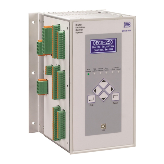
Basler DECS-250 Instruction Manual (352 pages)
Digital Excitation Control System
Brand:
Basler
| Category:
Controller
| Size: 9 MB
Table of Contents
Table of Contents
7
Introduction
17
Features and Functions
17
Applications
18
Package
18
Optional Features and Capabilities
18
Style Number
19
Storage
19
Electrolytic Capacitor Considerations
19
Controls and Indicators
21
Front Panel Illustration and Description
21
Menu Navigation
22
Adjusting Settings
23
Display Setup
23
Lcd
23
Sleep Mode
23
Language
23
Screen Scrolling
24
Power Inputs
25
Control Power
25
Operating Power
25
Inrush Current Reduction Module (ICRM)
25
Power Stage
27
Voltage and Current Sensing
29
Generator Voltage
29
Generator Current
29
Phase Sensing
29
Cross-Current Compensation
30
Bus Voltage
31
Synchronizer
33
Generator Synchronization
33
Frequency Correction
33
Voltage Correction
33
Angle Compensation
34
Failure of Synchronization
34
Voltage Matching
35
Breaker Hardware Configuration
35
Breaker Failure
35
Generator Breaker
35
Generator and Bus Condition Detection
36
Generator Condition
36
Generator Stability
37
Bus Condition
37
Bus Stability
37
Generator Governor Control
39
Regulation
41
Regulation Modes
41
Avr
41
Fcr
41
Fvr
41
Var
42
Power Factor
42
Pre-Position Setpoints
43
Transient Boost
44
Operation with Paralleled Generators
44
Reactive Droop Compensation
45
Cross-Current Compensation
45
Network Load Sharing
45
Line Drop Compensation
46
Autotracking
47
Internal Setpoint Tracking
47
External Setpoint Tracking
48
Setpoint Configure
48
Auxiliary Control
49
Auxiliary Control Input Type
49
Auxiliary Control Input Function
49
PSS Test Input
49
Limiter Scaling
49
Setpoint Limits
49
Auxiliary Control Gains
49
AVR Mode
50
FCR Mode
50
FVR Mode
50
Var Mode
50
Power Factor Mode
50
Summing Type
50
Contact Inputs and Outputs
53
Contact Inputs
53
Start and Stop Inputs
53
Programmable Inputs
53
Contact Outputs
54
Watchdog Output
54
Programmable Outputs
54
Protection
57
Voltage Protection
57
Overexcitation (Volts Per Hertz)
57
Generator Undervoltage
59
Generator Overvoltage
60
Loss of Sensing
60
Frequency Protection
61
Overfrequency
61
Underfrequency
62
Power Protection
62
Reverse Power
62
Loss of Excitation
63
Field Protection
64
Field Overvoltage
65
Field Overcurrent
65
Exciter Diode Monitor
66
Power Input Failure
68
Sync-Check Protection
69
Generator Frequency Less than 10 Hertz
70
Configurable Protection
70
Limiters
73
Overexcitation Limiter
73
Summing Point OEL
73
Takeover OEL
75
Underexcitation Limiter
77
Stator Current Limiter
79
Low-Level Limiting
79
High-Level Limiting
79
Initial Delay
79
Var Limiter
80
Limiter Scaling
80
Underfrequency Limiter
81
Volts Per Hertz
82
Metering
85
Metering Explorer
85
Hmi
85
Bestcomsplus
85
Metered Parameters
86
Generator
86
Power
86
Bus
87
Field
88
Pss
88
Synchronization
89
Auxiliary Control Input
89
Tracking
89
Control Panel
90
Metering Summary
91
Status Indication
92
System Status
92
Inputs
93
Outputs
94
Network Load Share
95
Configurable Protection
95
Alarms
96
Real-Time Clock
99
Auto Export Metering
100
Event Recorder
101
Sequence-Of-Events Recording
101
Data Logging
101
Setup
102
Triggers
102
Trending
105
Power System Stabilizer
107
Supervisory Function and Setting Groups
107
Supervisory Function
107
Setting Groups
107
Theory of Operation
107
Speed Signal
109
Rotor Frequency Calculation
109
Generator Electrical Power Signal
109
Derived Mechanical Power Signal
110
Stabilizing Signal Selection
110
Torsional Filters
111
Phase Compensation
111
Washout Filter and Logic Limiter
111
Output Stage
112
Terminal Voltage Limiter
112
Stability Tuning
117
AVR Mode
117
Predefined Stability Settings
117
Custom Stability Settings
117
Auto Tuning
119
FCR and FVR Modes
120
FCR Mode Stability Settings
120
FVR Mode Stability Settings
121
Other Modes and Functions
122
Var Mode
122
Power Factor Mode
122
Overexcitation Limiter (OEL)
122
Underexcitation Limiter (UEL)
122
Stator Current Limiter (SCL)
122
Var Limiter
122
Voltage Matching
122
Mounting
125
Mounting Considerations
125
Projection Mounting
125
Behind-The-Panel Mounting
125
Terminals and Connectors
129
Overview
129
Terminal Types
133
Typical Connections
135
Bestcomsplus Software
139
General Description
139
Installation
140
Install Bestcomsplus
140
Activation of the DECS-250 Plugin for Bestcomsplus
140
Connect a USB Cable
141
Start Bestcomsplus
141
And Activate DECS-250 Plugin Automatically
141
Manual Activation of the DECS-250 Plugin
143
Establishing Communication
144
Menu Bars
144
Upper Menu Bar (Bestcomsplus Shell)
144
Lower Menu Bar (DECS-250 Plugin)
146
Settings Explorer
146
Metering Explorer
146
Settings File Management
147
Opening a Settings File
147
Saving a Settings File
147
Upload Settings And/Or Logic to Device
147
Download Settings and Logic from Device
147
Printing a Settings File
147
Comparing Settings Files
147
Automatic Metering Export
149
Firmware Updates
149
Upgrading Firmware in Expansion Modules
150
Upgrading Firmware in the DECS-250
151
Bestcomsplus Updates
152
Bestlogic™Plus
153
Introduction
153
Overview of Bestlogic™Plus
153
Bestlogic™Plus Composition
154
Logic Schemes
168
The Active Logic Scheme
168
Sending and Retrieving Logic Schemes
168
Default Logic Schemes
169
Programming Bestlogic™Plus
172
Pickup and Dropout Timers
173
Offline Logic Simulator
174
Bestlogic™Plus File Management
174
Saving a Bestlogicplus File
175
Opening a Bestlogicplus File
175
Protecting a Bestlogicplus File
175
Uploading a Bestlogicplus File
175
Downloading a Bestlogicplus File
175
Copying and Renaming Preprogrammed Logic Schemes
175
Printing a Bestlogicplus File
175
Clearing the On-Screen Logic Diagram
176
Bestlogic™Plus Examples
176
Example 1 - GOVR Logic Block Connections
176
Example 2 - and Gate Connections
176
Communication
177
Local Communication
177
Communication with a Second DECS
177
Modbus™ Communication
178
RS-485 Port
178
Ethernet Port
179
CAN Communication
179
Connections
180
Port Configuration
180
Remote Module Setup
180
Ethernet Communication
181
Ethernet Connection
181
PROFIBUS Communication
184
Configuration
185
Generator, Field, and Bus Ratings
185
Bridge
186
Sensing Transformer Ratings and Configuration
186
Generator PT
187
Generator Cts
187
Bus PT
187
Startup Functions
187
Soft Start
188
Field Flashing
188
Device Information
188
Firmware and Product Information
189
Device Identification
189
Display Units
190
Security
191
Password Access
191
Password Creation and Configuration
191
Port Security
192
Port Access Configuration
192
Login and Access Controls
193
Access Timeout
193
Login Failure
193
Timekeeping
195
Time and Date Format
195
Daylight Saving Time Adjustments
195
Network Time Protocol (NTP)
195
NTP Settings
195
Irig
195
Testing
199
Real-Time Metering Analysis
199
Graph Parameters
200
Frequency Response
201
Test Mode
201
Bode Plotting
201
Transfer Function
201
Frequency Response
202
Time Response
202
Signal Input
203
Test Signal Characteristics
203
Step Response Analysis
204
AVR, FCR, and FVR Tabs
204
Var and PF Tabs
205
Analysis Options
205
Layout Tab
205
Graph Display Tab
206
CAN Communication
207
Introduction
207
CAN Parameters
207
Diagnostic Trouble Codes (Dtcs)
209
Modbus™ Communication
211
Introduction
211
Message Structure
211
Modbus Modes of Operation
212
Modbus™ over Serial Line
212
Modbus on TCP/IP
213
Error Handling and Exception Responses
214
DECS-250 Modbus™ Via Ethernet
214
Detailed Message Query and Response for RTU Transmission Mode
215
Read Holding Registers
215
Return Query Data
215
Restart Communications Option
216
Listen Only Mode
216
Preset Multiple Registers
216
Preset Single Register
217
Data Formats
218
Floating Point Data Format (Float)
218
Long Integer Data Format (Uint32)
218
Integer Data Format (Uint16) or Bit-Mapped Variables in Uint16 Format
219
Short Integer Data Format/Byte Character Data Format (Uint8)
219
String Data Format (String)
219
CRC Error Check
220
Secure DECS-250 Login Via Modbus
220
Modbus Parameters
220
General
220
Security
221
Binary Points
221
Metering
230
Limiters
235
Setpoints
238
Global Settings
239
Relay Settings
241
Protection Settings
242
Gains Settings
244
Legacy Modbus
245
PROFIBUS Communication
253
Data Types
253
Float/Uint32
253
Uint8
253
Setup
255
PROFIBUS Parameters
256
Maintenance
301
Storage
301
Preventive Maintenance
301
Connections
301
Electrolytic Capacitors
301
Cleaning the Front Panel
302
Troubleshooting
302
DECS-250 Appears Inoperative
302
Display Blank or Frozen
302
Generator Voltage Does Not Build
302
Low Generator Voltage in AVR Mode
302
High Generator Voltage in AVR Mode
303
Generator Voltage Unstable (Hunting)
303
Protection or Limit Annunciation
303
HMI Meter Readings Incorrect
303
No Communication
303
DECS-250 Reboots Frequently
303
Support
303
Specifications
305
Operating Power
305
Control Power
305
Style LXXXXXX
305
Style CXXXXXX
306
Terminals
306
Generator and Bus Voltage Sensing
306
50 Hz Sensing Voltage Nominal Input, Range
306
Generator Current Sensing
306
Accessory Inputs
307
Current Input
307
Voltage Input
307
Contact Inputs
307
Terminals
307
Communication Ports
307
Universal Serial Bus (USB)
307
Ethernet
308
Controller Area Network (CAN)
308
IRIG Time Synchronization Input
308
Contact Outputs
308
Rs-485
308
Field Power Output
309
Minimum 10-Second Forcing Output Rating
309
Minimum Field Resistance
309
Regulation
309
FCR Operating Mode
309
FVR Operating Mode
309
AVR Operating Mode
309
Var Operating Mode
309
Parallel Compensation
310
Reverse Power (32R)
311
Synchronism Check (25) Protection
312
On-Line Overexcitation Limiting
313
Environment
314
Physical
315
Analog Inputs
317
RTD Inputs
317
Thermocouple Inputs
317
Analog Outputs
317
Analog Expansion Module
317
Communication Interface
318
Type Tests
318
Environment
318
UL Approval
318
CSA Certification
318
CE Compliance
319
Physical
319
Installation
319
Mounting
319
Connections
320
Communications
326
Functional Description
326
Analog Inputs
326
RTD Inputs
327
Thermocouple Inputs
328
Analog Outputs
329
Metering
330
Analog Inputs
330
RTD Inputs
331
Thermocouple Inputs
331
Analog Input Values
331
Analog Outputs
333
Maintenance
333
Firmware Updates
333
Contact Expansion Module
335
General Information
335
Features
335
Specifications
335
Operating Power
335
Contact Inputs
335
Contact Outputs
335
Communication Interface
335
Type Tests
335
Environment
336
UL Approval (CEM-2020 and CEM-2020H)
336
CSA Certification
336
CE Compliance
336
Physical
337
Installation
337
Mounting
337
Connections
339
Communications
344
Functional Description
344
Contact Inputs
344
Contact Outputs
345
Metering
346
Contact Inputs
346
Contact Outputs
346
Maintenance
346
Firmware Updates
346
Revision History
347
Advertisement
Basler DECS-250 Instruction Manual (344 pages)
DIGITAL EXCITATION
Brand:
Basler
| Category:
Control Systems
| Size: 12 MB
Table of Contents
Table of Contents
5
Introduction
9
Features and Functions
9
Application
10
Package
10
Optional Features and Capabilities
10
Storage
11
Controls and Indicators
13
Front Panel Illustration and Description
13
Menu Navigation
14
Adjusting Settings
15
Display Setup
15
Power Inputs
17
Control Power
17
Operating Power
17
Power Stage
19
Voltage and Current Sensing
21
Generator Voltage
21
Generator Current
21
Bus Voltage
23
Synchronizer
25
Generator Synchronization
25
Voltage Matching
27
Breaker Hardware Configuration
27
Generator and Bus Condition Detection
28
Generator Governor Control
31
Regulation
33
Regulation Modes
33
Pre-Position Setpoints
35
Transient Boost
36
Operation with Paralleled Generators
37
Autotracking
39
Setpoint Configure
40
Auxiliary Control
41
Auxiliary Control Input Type
41
Auxiliary Control Input Function
41
Auxiliary Control Gains
41
Summing Type
42
Contact Inputs and Outputs
43
Contact Inputs
43
Contact Outputs
44
Protection
47
Voltage Protection
47
Frequency Protection
51
Power Protection
52
Field Protection
55
Sync-Check Protection
59
Generator Frequency Less than 10 Hertz
60
Configurable Protection
60
Limiters
63
Overexcitation Limiter
63
Underexcitation Limiter
67
Stator Current Limiter
69
Var Limiter
70
Limiter Scaling
71
Underfrequency Limiter
71
Metering
75
Metering Explorer
75
Metered Parameters
76
Status Indication
82
Auto Export Metering
90
Event Recorder
91
Sequence-Of-Events Recording
91
Data Logging
91
Trending
95
Power System Stabilizer
97
Supervisory Function and Setting Groups
97
Theory of Operation
97
Stability Tuning
107
AVR Mode
107
FCR and FVR Modes
111
Other Modes and Functions
112
Mounting
115
Mounting Considerations
115
Projection Mounting
115
Behind-The-Panel Mounting
115
Terminals and Connectors
119
Overview
119
Terminal Types
123
Typical Connections
125
Bestcomsplus
129
Software
129
General Description
129
Installation
130
Activation of the DECS-250 Plugin for Bestcomsplus
130
Menu Bars
134
Settings Explorer
136
Metering Explorer
137
Settings File Management
137
Automatic Metering Export
139
Firmware Updates
140
Bestcomsplus Updates
143
Bestlogic™Plus
145
Introduction
145
Overview of Bestlogic™Plus
145
Logic Schemes
159
Programming Bestlogic™Plus
164
Bestlogic™Plus File Management
166
Bestlogic™Plus Examples
167
Communication
169
Local Communication
169
Communication with a Second DECS
169
Modbus™ Communication
170
CAN Communication
172
Ethernet Communication
173
PROFIBUS Communication
176
Configuration
177
Generator, Field, and Bus Ratings
177
Bridge
178
Sensing Transformer Ratings and Configuration
178
Startup Functions
179
Device Information
180
Display Units
182
Security
183
Password Access
183
Port Security
184
Login and Access Controls
185
Timekeeping
187
Time and Date Format
187
Daylight Saving Time Adjustments
187
Network Time Protocol (NTP)
187
Irig
187
Testing
191
Real-Time Metering Analysis
191
Frequency Response
193
Time Response
194
Step Response Analysis
196
Analysis Options
197
CAN Communication
199
Introduction
199
CAN Parameters
199
Modbus™ Communication
203
Introduction
203
Modbus Modes of Operation
204
Detailed Message Query and Response for RTU Transmission Mode
207
Data Formats
210
Secure DECS-250 Login Via Modbus
212
Modbus Parameters
213
PROFIBUS Communication
245
Data Types
245
Setup
248
PROFIBUS Parameters
248
Maintenance
295
Storage
295
Preventive Maintenance
295
Cleaning the Front Panel
296
Troubleshooting
296
Support
297
Specifications
299
Operating Power
299
Control Power
299
Generator and Bus Voltage Sensing
300
Generator Current Sensing
300
Accessory Inputs
300
Contact Inputs
301
Communication Ports
301
IRIG Time Synchronization Input
302
Contact Outputs
302
Field Power Output
303
Regulation
303
Parallel Compensation
303
Generator Protection Functions
304
Field Protection Functions
305
Synchronism Check (25) Protection
305
Startup
306
Voltage Matching
306
On-Line Overexcitation Limiting
306
Off-Line Overexcitation Limiting
307
Sequence of Events Recording (SER)
307
Data Logging (Oscillography)
307
Environment
307
Type Tests
307
Patent
308
Physical
308
Regulatory Standards
308
Analog Expansion Module
311
General Information
311
Features
311
Specifications
311
Installation
313
Communications
320
Functional Description
320
Metering
324
Maintenance
327
Contact Expansion Module
329
General Information
329
Features
329
Specifications
329
Installation
331
Communications
338
Functional Description
338
Metering
340
Maintenance
340
Revision History
341
Basler DECS-250 Instruction Manual (374 pages)
Digital Excitation Control System
Brand:
Basler
| Category:
Control Systems
| Size: 10 MB
Table of Contents
Table of Contents
11
Introduction
13
Controls and Indicators
17
Power Inputs
21
Power Stage
23
Voltage and Current Sensing
25
Synchronizer
29
Regulation
35
Auxiliary Control
45
Contact Inputs and Outputs
49
Protection
53
Limiters
69
Grid Code
81
Metering
101
Event Recorder
117
Power System Stabilizer
123
Stability Tuning
133
Mounting
139
Terminals and Connectors
143
Typical Connections
149
Bestcomsplus ® Software
153
Bestlogic™Plus
169
Communication
197
Configuration
205
Security
211
Timekeeping
215
Testing
217
CAN Communication
225
Modbus® Communication
229
PROFIBUS Communication
277
Maintenance
327
Specifications
331
Analog Expansion Module
343
Contact Expansion Module
361
Advertisement
Basler DECS-250 Instruction Manual (8 pages)
Digital Excitation Control System
Brand:
Basler
| Category:
Control Systems
| Size: 0 MB
Advertisement
Related Products
Basler DECS-200
Basler DGC-2020ES
Basler DGC-500
Basler DGC-2020
Basler DGC-2020HD
Basler DECS-400
Basler DECS-250N
Basler DECS-100
Basler DECS-150
Basler daA2500-60mc-SD820-DB8
Basler Categories
Relays
Digital Camera
Controller
Security Camera
Protection Device
More Basler Manuals
Login
Sign In
OR
Sign in with Facebook
Sign in with Google
Upload manual
Upload from disk
Upload from URL