Table of Contents
Advertisement
Quick Links
C60_2-028_823024_0401-e.p65
1
2
No. 823 024 D/E • Edition 0401
Subject to modification.
Replaces edition 0301.
http://www.balluff.de
http://www.balluff.de
http://www.balluff.de
http://www.balluff.de
http://www.balluff.de
Balluff GmbH
Schurwaldstrasse 9
73765 Neuhausen a.d.F.
Germany
Phone +49 (0) 71 58/1 73-0
Fax +49 (0) 71 58/50 10
E-Mail: balluff@balluff.de
2
E
Electronic Identification Systems BIS
Processor BIS C-60_2
Profibus DP with Memory Optimization
Deutsch – bitte wenden!
Manual
Advertisement
Table of Contents

Related Manuals for Balluff BIS C-6002


Summary of Contents for Balluff BIS C-6002
- Page 1 No. 823 024 D/E • Edition 0401 Subject to modification. Replaces edition 0301. http://www.balluff.de http://www.balluff.de http://www.balluff.de http://www.balluff.de http://www.balluff.de Balluff GmbH Schurwaldstrasse 9 73765 Neuhausen a.d.F. Germany Phone +49 (0) 71 58/1 73-0 Fax +49 (0) 71 58/50 10 E-Mail: balluff@balluff.de...
-
Page 2: Table Of Contents
Should there ever be indications that the identification system is not working properly, it Fault Conditions should be taken out of commission and secured from unauthorized use This manual applies to processors in the series BIS C-6002-028-...-03-_ _ _ and Scope BIS C-6022-028-050-03-ST.. -
Page 3: Introduction Bis C Identification Systems
System Components The main components of the BIS C Identification Systems are: – Processor, – Read/Write Heads and – Data carriers Configuration with PROFIBUS-DP BIS C-6002 processor Processor BIS C-6002 Processor BIS C-6002 with with adapter adapter Processor BIS C-6002 Read/write... -
Page 4: Bis C-60_2 Processor Basic Knowledge For Application
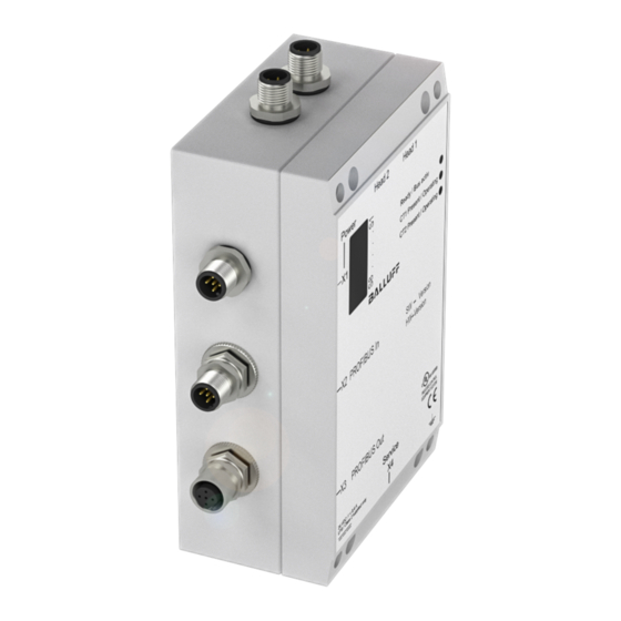
BIS C-60_2 Processor Basic knowledge for application The BIS C-6002 processor has a plastic housing. Depending on the version, connections are Selecting System made either through a terminal strip, with the cable secured using a PG fitting, or via round Components connectors. -
Page 5: Optimized Data Carrier Memory Management
Optimized data carrier memory management Protocol The BIS C-60_2-028 version works with a further developed Balluff protocol, which optimizes memory handling in the data carrier. This version would be required whenever the required number of write cycles exceeds the number permitted for the EEPROM in the data carrier. -
Page 6: Bus Interface Profibus-Dp
In this method the PLC cycle is unaffected nor is the bus access time changed. All that is required is that a byte in the data buffer be used for the 2nd bit header instead of for user data. This 2nd alternative is the Balluff recommended setting (factory default). - Page 7 19 18 17 16 15 14 13 12 11 10 9 8 7 6 5 4 3 2 1 Slide switch S1 (with cover removed) To open the cover of the processor, see 50 for BIS C-6002 or 66 for BIS C-6022.
-
Page 8: Compatibility With Bis C-6_2 Processor
In the illustration compatibility with the BIS C-6_2 is not set. 19 18 17 16 15 14 13 12 11 10 9 8 7 6 5 4 3 2 1 To open the cover of the BIS C-6002 processor, see and for BIS C-6022 see... -
Page 9: Input And Output Buffers
C60_2-028_823024_0401-e.p65 Function Description Input and Output Buffers Input and Output In order to transmit commands and data between the BIS C-60_2 and the host system, the Buffers latter must prepare two fields. These two fields are: – the output buffer for the control commands which are sent to the BIS Identification System and for the data to be written. -
Page 10: Output Buffer, Configuration And Explanation
C60_2-028_823024_0401-e.p65 Function Description Output buffer, configuration and explanation Configuration of the The last byte can be arranged as a 2nd bit header through parametering (default). output buffer for one (1) read/write head Sub- Meaning Function Description Description of address Name Output Buffer Data carrier type Select data carrier type: for data carrier type:... -
Page 11: Output Buffer, Configuration And Explanation
C60_2-028_823024_0401-e.p65 Function Description Output buffer, configuration and explanation Description of Sub- Meaning Function Description Output Buffer address (continued) Start address Address at which reading from or writing to the data carrier begins (Low Byte) (the Low Byte includes the address range from 0 to 255). (Das Low Byte deckt den Adressbereich von 0 bis 255 ab). -
Page 12: Input Buffer, Configuration And Explanation
C60_2-028_823024_0401-e.p65 Function Description Input buffer, configuration and explanation Configuration of the The last byte can be arranged as a 2nd bit header through parametering (default). input buffer for one (1) Read/Write head Sub- Meaning Function Description Description of address Name Input Buffer Ready The BIS Identification System is in the Ready state. - Page 13 C60_2-028_823024_0401-e.p65 Function Description Input buffer, configuration and explanation Description of Sub- Meaning Function Description Input Buffer address (continued) Error code (continued) Data carrier was removed from the active zone of the read/write head while it was being written. 07Hex AV bit is set but the command designator is missing or invalid. Number of bytes is 00Hex.
-
Page 14: Parametering The Bis C-60_2 Processor
C60_2-028_823024_0401-e.p65 Function Description Parametering the BIS C-60_2 processor Parameters, There are 6 user parameter bytes stored on the Profibus master that can be used to activate Overview and deactivate various functions. Setting is done directly by linking a device to the Profibus master. -
Page 15: Processing Data Carriers
C60_2-028_823024_0401-e.p65 Function Description Parametering the BIS C-60_2 processor Parametering Bytes 4th byte, bit 8, Arrange a 2nd bit header at the end of the input and output buffers. (continued) If this function is selected, then the minimum size of both buffers is 4 words (8 bytes) each. 4th byte, bit 7, Display state of the digital input in the bit header of the input buffers: 0 = no... -
Page 16: Reading And Writing In Dynamic Mode
C60_2-028_823024_0401-e.p65 Function Description Processing data carriers Special To adjust the read/write functions to the numerous possible applications, a few unique fea- characteristics tures have been implemented that the user can select and set when parametering or program- ming the processor. These are as follows: Reading and writing In normal operation a read/write job is rejected by the BIS C-60_2 processor by setting the AF in dynamic mode... -
Page 17: Monitoring Data Carrier Initialization
To store a second program, repeat this process. The procedure for writing these settings to the EEPROM is described in the 7th example on 40...42. Replacing the EEPROM is described on 59 for BIS C-6002 and on 71 for BIS C-6022. Function Description Monitoring initialization, splitting memory... -
Page 18: Examples For Protocol Sequence
C60_2-028_823024_0401-e.p65 Function Description Examples for protocol sequence Example No. 1 Initializing the data carrier for memory optimization (data carrier type with 32 byte block size) For configuring with Host: BIS C-60_2 Identification System: double bit header and 8-byte buffer 1.) Process subaddresses of the output buffer in the 2.) Process subaddresses of the input buffer in the order shown: size! - Page 19 C60_2-028_823024_0401-e.p65 Function Description Examples for protocol sequence Example No. 4 Read 17 bytes starting at data carrier address 10 (data carrier type with 32 byte block size): Host: BIS C-60_2 Identification System: For configuring with 1.) Process subaddresses of the output buffer in the 2.) Process subaddresses of the input buffer in the double bit header order shown:...
- Page 20 C60_2-028_823024_0401-e.p65 Function Description Examples for protocol sequence Example No. 6 Write 16 bytes starting at data carrier address 20 (data carrier type with 32 byte block size): Host: BIS C-60_2 Identification System: For configuring with 1.) Process subaddresses of the output buffer in the 2.) Process subaddresses of the input buffer in the double bit header order shown:...
- Page 21 C60_2-028_823024_0401-e.p65 Function Description Examples for protocol sequence Example No. 7 Host: Host: Store Mixed Data 5.) Process subaddresses of the output buffer: 6.) Process subaddresses of the input buffer: Access program (continued) For configuring with double bit header and 8-byte buffer size! 7.) Process subaddresses of the output buffer: 8.) Process subaddresses of the input buffer:...
- Page 22 C60_2-028_823024_0401-e.p65 Function Description Examples for protocol sequence Example No. 8 Read data carrier using Program No. 1 (data carrier type with 32 byte block size): Use Mixed Data Host: BIS C-60_2 Identification System: Access program 1.) Process subaddresses of the output buffer in the 2.) Process subaddresses of the input buffer in the order shown: order shown:...
-
Page 23: Read/Write Times
C60_2-028_823024_0401-e.p65 Function Description Examples for protocol sequence Example No. 10 Put the relevant read/write head into ground state: Both read/write heads can be independently set to the ground state. Host: BIS C-60_2 Identification System: 1.) Process subaddresses of the output buffer: 2.) Go to ground state;... -
Page 24: Led Display
C60_2-028_823024_0401-e.p65 Read/Write Times Read times from Read times within the 1st block for dual read and compare: data carrier to processor in The indicated times apply after the data carrier has been recognized. If the data carrier is not dynamic mode yet recognized, an additional 45 ms for building the required energy field until the data carrier is recognized must be added. -
Page 25: Mounting Head / Processor
4 M4 screws. BIS C-6002 processor BIS C-6002 Opening the Processor Opening the The BIS C-6002 processor must be opened to perform the following steps: Processor – Set PROFIBUS-DP address BIS C-6002 – Activate/deactivate termination resistor – Set/change compatibility mode –... - Page 26 C60_2-028_823024_0401-e.p65 BIS C-6002-...-KL2 Installing the connection cables Make connections The BIS C-6002 processor must be opened in order to make the connections for the supply on the BIS C-6002 voltage, the digital input and the PROFIBUS connections (see 50). processor First be sure that the unit is disconnected from power.
-
Page 27: Interface Information / Wiring Diagrams
You can either use the connections 1 and 2 or 5 and 6. The last bus module must terminate the bus with a resistor. In the case of the BIS C-6002, this can be realized in two different ways: Terminating resistor 1. - Page 28 C60_2-028_823024_0401-e.p65 BIS C-6002-...-KL2 Interface Information / Wiring Diagrams Wiring diagram Connection for Read/Write Head 1 for BIS C-6002 Connection for processors with Read/Write Head 2 BIS C-650 adapter Head 1 Head 2 01 = CT Present 1 02 = CT Present 2...
- Page 29 BIS C-6002-...-ST11 Interface Information / Wiring Diagrams Remote bus cable To insert BIS C-6002-...-ST11 processor into the serial PROFIBUS-DP, there are the terminal for PROFIBUS-DP X2 for the PROFIBUS input and the terminal X3 for the PROFIBUS output. Bus station Bus station BIS C-6002-...-ST11...
-
Page 30: Changing The Eeprom
C60_2-028_823024_0401-e.p65 BIS C-6002 Changing the EEPROM Changing the To replace the EEPROM, open up the processor as described on EEPROM in the BIS C-6002 processor Be sure before opening that the unit is discon- nected from power.. To avoid damaging the EEPROM, please ob- serve the requirements for handling electrostati- cally sensitive components. - Page 31 89/336/EEC (EMC-Guideline) and the EMC Law. Testing in our EMC Laboratory, which is accredited by the DATech for Testing of Electromagnetic Compatibility, has confirmed that Balluff products meet the EMC requirements of the Generic Standard EN 61000-6-4 (Emission) and EN 61000-6-2 (Noise Immunity).
-
Page 32: Ordering Information
C60_2-028_823024_0401-e.p65 BIS C-6002 Ordering Information BIS C-6002-028-_ _ _-03-_ _ _ Ordering Code Balluff Identification System Type C Read/Write System Hardware Type 6002 = plastic housing, PROFIBUS-DP Software-Type 028 = PROFIBUS-DP with memory optimization Read/Write Head 000 = no read/write head... - Page 33 C60_2-028_823024_0401-e.p65 BIS C-6022 Mounting Processor Mounting the The processor is mounted using 4 M4 screws. BIS C-6022 processor Head 2 Head 1 ca. 20 BIS C-6022 Opening the processor / Interface information Opening the To set the PROFIBUS-DP address, activate or deactivate the internal termination resistor, set BIS C-6022 the compatibility mode or to change the EEPROM, you must open up the BIS C-6022 proces- processor...
- Page 34 C60_2-028_823024_0401-e.p65 BIS C-6022 Interface Information / Wiring Diagrams To insert BIS C-6022 processor into the serial PROFIBUS and to connect the supply voltage and the digital input, the cables have to be connected to the terminals of the processor. For more details regarding the wiring see the following .
- Page 35 C60_2-028_823024_0401-e.p65 BIS C-6022-...-ST10 Interface Information / Wiring Diagrams Wiring diagram for Head 2 Head 1 X1, supply voltage, digital input, and BIS C-6022-...-ST10 CT Present outputs processor .unction X2, PROFIBUS output .unction Head 1 X3, PROFIBUS input Head 2 19 18 17 16 15 14 13 12 11 10 9 8 7 6 5 4 3 2 1 n.c.
- Page 36 C60_2-028_823024_0401-e.p65 BIS C-6022 Changing the EEPROM Changing the To change the EEPROM, open the processor as described on EEPROM in the BIS C-6022 processor Be sure before opening that the unit is disconnected from power. Head 2 Head 1 To avoid damaging the EEPROM, please observe the requirements for handling electrostatically sensitive components.
- Page 37 89/336/EEC (EMC-Guideline) and the EMC Law. Testing in our EMC Laboratory, which is accredited by the DATech for Testing of Electromagnetic Compatibility, has confirmed that Balluff products meet the EMC requirements of the Generic Standard EN 61000-6-4 (Emission) and EN 61000-6-2 (Noise Immunity).
-
Page 38: Appendix, Ascii Table
C60_2-028_823024_0401-e.p65 Appendix, ASCII Table Deci- Control Deci- Control Deci- Deci- Deci- Deci- ASCII ASCII Hex ASCII Hex ASCII Hex ASCII Hex ASCII Code Code...
Need help?
Do you have a question about the BIS C-6002 and is the answer not in the manual?
Questions and answers