Table of Contents
Advertisement
Advertisement
Table of Contents

Subscribe to Our Youtube Channel
Related Manuals for Grundfos MGE-F


Summary of Contents for Grundfos MGE-F
- Page 1 GRUNDFOS INSTRUCTIONS MGE model F Service instructions...
- Page 2 Preface These service instructions describe fault finding of pumps with Grundfos motors, type MGE model F (hereafter called MGE-F). The service instructions are aimed at specially trained staff who are familiar with the service of electrotechnical products. The use of these service instructions presupposes knowledge of these documents: •...
-
Page 3: Table Of Contents
Contents Identification ..........................4 Nameplates..............................4 Type key ..............................5 Configuration .............................. 5 General description ........................6 Wiring diagrams and signal terminals......................6 Control panel .............................. 7 Indicator lights............................. 8 Setting using the R100 remote control ....................... 8 R100 menu structure ..........................9 Alarms and warnings .......................... -
Page 4: Identification
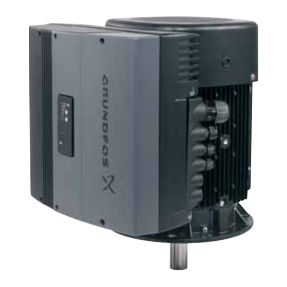
1. Identification 1.1 Nameplates The MGE-F nameplate (fig. 1) is fitted on the side of the terminal box (fig. 2). 9 10 Type Serial No : TP 211 P.N. P.C. Env.Type : 3R PF : Made in Hungary INPUT OUTPUT... -
Page 5: Type Key
See figs and 6. Fig. 5 Configuration label Fig. 6 Position of configuration label If the terminal box is replaced or mounted on another motor, it must be reconfigured. Contact Grundfos Service. 5 / 32... -
Page 6: General Description
2. General description Rectifier Intermediate circuit Inverter RFI filter Inrush circuit Driver circuit Control circuit Fig. 7 Block diagram showing the functional blocks of the frequency converter 2.1 Wiring diagrams and signal terminals The wiring diagram and the signal terminals depend on the pump application. Figures are examples of the different functional modules available. -
Page 7: Control Panel
A: RS485A (ext. bus) TWIN PUMP Y: RS485 GND (ext. bus) SWITCH B: RS485B (ext. bus) CONNECTION FOR A1: RS485A (int. bus ) TWIN PUMP Y: RS485 GND (int. bus) B1: RS485B (int. bus ) 7: SENSOR INPUT 8: +24V 9: GND 1: DIGITAL INPUT 1 7: SENSOR INPUT... -
Page 8: Indicator Lights
2.3 Indicator lights 2.3.1 Indicator lights on the control panel The indicator lights on the control panel show the MGE-F motor's operating and alarm condition. 2.3.2 Indicator lights inside the terminal box The indicator lights beside the terminal block on the control board normally have the same functions as the indicator lights on the control panel. -
Page 9: R100 Menu Structure
The R100 menus will adapt to the application set and possible functional modules. The menu structure below applies to a CRE pump. To see the correct menu structure, see Note installation and operating instructions for the pump on which the MGE-F motor is mounted. 0. GENERAL 1. OPERATION 2. -
Page 10: Alarms And Warnings
All service work must be carried out by specially trained staff. Warning Due to the capacitors of the MGE-F, touching live electrical parts may be fatal, even after the mains supply has been switched off. Disconnect the mains supply, and as a minimum wait the amount of time stated on the warning label under the terminal box cover before touching any live parts. -
Page 11: Operating Conditions
2.1 Wiring diagrams and signal terminals and installation and operating instructions for MGE 160 and MGE 180. • Check that terminals 2 and 3 are connected and that the MGE-F has been started via the control panel. Sensors connected •... -
Page 12: Fault Finding Using The Indicator Lights On The Control Panel
Has the communication cable been disconnected? been activated, but YES: Check the communication cable. there is no Contact Grundfos Service. communication with the standby pump. 2. The pump is running at a) Does the sensor setting correspond to the sensor type installed? maximum speed. - Page 13 Indicator lights Condition/cause Remedy Green 3. The pump is running at a) Set the pump to "open loop" operation, and connect 10 V supply to minimum speed. the setpoint input. – The setpoint signal is Does the pump switch to maximum speed? outside the set signal Proceed to point b).
- Page 14 Indicator lights Condition/cause Remedy Green Normal operation 1. The pump is running. – Normal operational state. 2. The pump is not running. a) The flow switch is closed. Operational stop which may be caused by – the flow switch connected –...
- Page 15 3. The terminal box is Replace the terminal box, or contact Grundfos Service. defective. [To be continued on the next page] 15 / 32...
- Page 16 • with the button • with the R100 • using the Grundfos GENIbus • by the motor start/stop function. (Input on terminal 2-3 is open). Flashing, Normal operational stop + indication of previous fault 1 Hz The pump has been stopped •...
-
Page 17: Fault Finding Using Alarm And Warning Codes
Replace varistor Motor varistor(s) need change (service information) The varistor has been exposed to the allowable Contact Grundfos Service. number of transients and needs replacing. Overvoltage Overvoltage The supply voltage has been or is too high. - Page 18 Cause: • Continued overload. • Reduce the load by limiting the pump flow. • Incorrect configuration of the terminal box. • Contact Grundfos Service. • Fault in stator windings. • Contact Grundfos Service. Underload Underload The motor is underloaded. Cause: •...
- Page 19 100 °C. The measured temperature can be read via PC Tool E-products. Cause: • Temperature sensor defective. • Contact Grundfos Service. • Continued overload. • Reduce the load. • The ambient temperature is too high, or •...
- Page 20 Explanation/cause Remedy Other fault Internal communication failure in frequency converter Internal communication fault in the pump due to defect Contact Grundfos Service. in the terminal box. Temperature sensor 2 signal outside Temperature sensor 2 signal fault signal range Same as fault 91.
-
Page 21: Maintenance
The recommended grease type and quantity and the recommended lubrication intervals in hours appear from the lubricating plate fitted to the motor. When the MGE-F has reached the prescribed number of operating hours, it will give a lubrication warning (fig. 17) that will appear on the R100 or PC Tool E-products. See section 2.6 Alarms and... -
Page 22: Replacement Of Motor Bearings
4.2 Replacement of motor bearings When the MGE-F has reached the prescribed number of operating hours, it will give a warning about replacement of bearings (fig. 19) that will appear on the R100 or PC Tool E-products. See section 2.6 Alarms and warnings. - Page 23 15. Confirm the replacement of the bearings in the INSTALLATION menu of the R100 (or via PC Tool Fig. 22 Detail from fig. 29, exploded view of the MGE-F E-products). See fig. 21. Fig. 21 Confirmation of bearing lubrication...
-
Page 24: Emergency Operation (Bypass)
5. Emergency operation (bypass) If it is necessary to continue pump operation even if replacement or repair of the terminal box is not possible, establish emergency operation by connecting the motor direct to the mains supply. Before establishing emergency operation of the pump, make sure that the motor is OK. Caution You may for instance meg the motor. -
Page 25: Re-Establishment Of Frequency Converter Operation
5. Pull the insulating hose around the motor conductors up over the joint. Wind insulating tape or similar around the ends of the insulating hose in order to fasten it over the joint. See figs and 28. Fig. 27 Insulating the joint Fig. -
Page 26: Drawings And Diagrams
6. Drawings and diagrams The position numbers in fig. refer to the list on page 27. Fig. 29 Exploded view, MGE-F 26 / 32... - Page 27 Position numbers Pos. Description Fan cover Screw, fan cover 152a Rubber bushing Ball bearing, drive end Ball bearing, non-drive end 155a Inner bearing cover, drive end 155d Inner bearing cover, non-drive end 156a Bearing end shield, non-drive end 156b Bearing end shield, drive end 156c Circlip for fan O-ring, bearing, non-drive end flange...
- Page 28 The position numbers in fig. refer to the list on page 29. Fig. 30 Exploded view, terminal box 28 / 32...
- Page 29 Position numbers Pos. Description Terminal box cover Screw for terminal box cover 251a Terminal box, lower part 251b Terminal box top 251c Gasket for terminal box top 251d Screw for terminal box top 251e Screw for terminal box top Cable entry block, complete Screw for cable entry block, Control panel Functional module, complete with plugs...
-
Page 30: Tightening Torques And Lubrication
Lubricating intervals, grease quantity and type appear from the motor lubricating plate. Pos. Description Bearing, drive end Grease type Ambient temperature Ambient temperature Bearing, non-drive end Quantity of grease Lubricating interval Lubricating interval Fig. 31 Lubricating plate of MGE-F 30 / 32... -
Page 31: Service Tools
8. Service tools Special tools Pos. Designation Supplementary information Product number R100 96615297 PC Tool E-products 96562869 Standard tools Pos. Designation Supplementary information Product number Puller Slotted screwdriver ® Torx screwdrivers (set) T20, T25 96884908 Hexagon socket screwdriver 8 mm Torque tools Pos. - Page 32 Tel.: +43-6246-883-0 Telefax: +49-(0) 211 929 69-3799 Veluwezoom 35 Turkey Telefax: +43-6246-883-30 e-mail: infoservice@grundfos.de 1326 AE Almere GRUNDFOS POMPA San. ve Tic. Ltd. Sti. Service in Deutschland: Postbus 22015 Gebze Organize Sanayi Bölgesi Belgium e-mail: kundendienst@grundfos.de 1302 CA ALMERE N.V. GRUNDFOS Bellux S.A.
Need help?
Do you have a question about the MGE-F and is the answer not in the manual?
Questions and answers