
Related Manuals for Accorroni MEC MIX C


Summary of Contents for Accorroni MEC MIX C
- Page 1 Wall mounted air heaters with premixed gas burner MEC MIX C condensation and modulation MEC MIX F fixed power...
-
Page 3: Technical Information
6 - A2B Accorroni E.G. S.r.l. is responsible for product’s conformity to the laws, directives and technical regulation in force on the date of commercialization. A2B Accorroni E.G. S.r.l. is not responsible for plant design, use and maintenance’s compliance with laws and regulation in force. -
Page 4: Table Of Contents
GENERAL FEATURES ......................5 Description of operation ......................5 Construction features ......................... 5 Table of technical data MEC MIX C condensation axial ............6 Table of technical data MEC MIX F axial .................. 6 Wiring diagram MEX MIX C condensation centrifuge ..............7 Table of technical data MEC MIX F centrifuge ................ -
Page 5: General Warnings
SECTION A - GENERAL INFORMATION 1. GENERAL WARNINGS 2.5 USE Do not allow children nor not qualified operators The present manual is integral part of the product. of running the unit. It must be stored carefully for any future use or reference. -
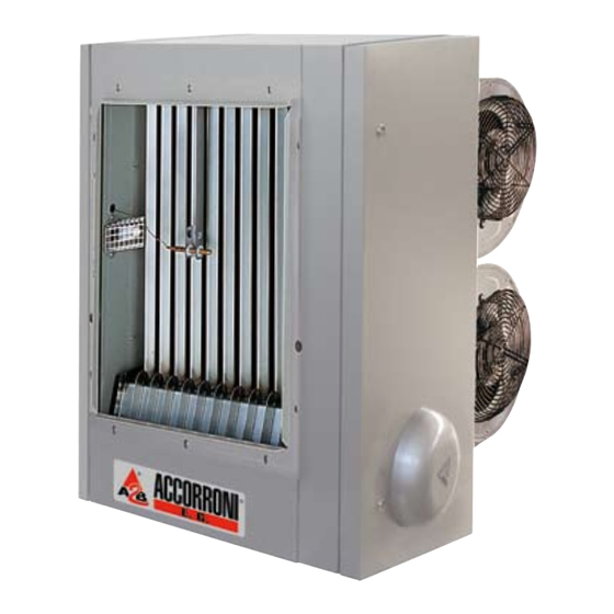
Page 6: General Features
3. GENERAL FEATURES In summer mode the unit can run the air blower either in automatic or manual mode, in order to have a pleasant 3.1 DESCRIPTION OF OPERATION air circulation inside the room. The MEC MIX COND is classified as individual gas- fired air heater equipped with hermetically sealed 3.2 CONSTRUCTION FEATURES combustion chamber and premix-burner. -
Page 7: Table Of Technical Data Mec Mix C Condensation Axial
3.3 TABLE OF TECHNICAL DATA MEC MIX C CONDENSATION AXIAL 3.4 TABLE OF TECHNICAL DATA MEC MIX F AXIAL... -
Page 8: Table Of Technical Data Mec Mix F Centrifuge
3.5 TABLE OF TECHNICAL DATA MEC MIX C CONDENSATION CENTRUFUGE 3.6 TABLE OF TECHNICAL DATA MEC MIX F CENTRUFUGE... - Page 9 Serie MEC MIX C condensation model 20/35 - 20/45 centrifuge fans Serie MEC MIX F model 35-50 centrifuge fans TOP VIEW connection air inlet exhaust Condensate outlet Drain Values in mm * The condensate drain is present only in the Model MEC MIX C...
- Page 10 Serie MEC MIX C condensation model 20/35 - 20/45 axial fans Serie MEC MIX F model 35-50 axial fans TOP VIEW connection exhaust Condensate air inlet outlet Drain Values in mm * The condensate drain is present only in the Model MEC MIX C...
- Page 11 Dimensions Serie MEC MIX C condensation model 20/70 – 20/90 centrifuge Serie MEC MIX F model 70-100 centrifuge connection connection air inlet air inlet exhaust exhaust outlet outlet Values in mm...
- Page 12 3.10 Dimensions Serie MEC MIX C condensation model 20/70 – 20/90 axial Serie MEC MIX F model 70-100 axial connection connection air inlet air inlet exhaust exhaust outlet outlet Values in mm...
-
Page 13: Electrical Wiring
3.11 Electrical wiring - Range MEC MIX C/F LEGEND FAN2 Air motor fan 2 ACC1 Remote ignition transformer Chrono-thermostat Capacitor 1 (5μF) Detecting electrode Capacitor 2 (5μF) Terminal 1 Ignition electrode RESET Reset button Premix blower Room temperature sensor (optional) -
Page 14: Control And Safety
SECTION B - OPERATING AND MAINTENANCE 4. CONTROL AND SAFETY control used as room or outdoor temperature the MEC MIX COND are shown. The unit is operated sensor byBRAHMATC340 control board. The control panel - possibility of connecting afire damper actuator also includes the room temperature thermostat, - possibility of connecting an analogue signal programmable timer and function/failure display. -
Page 15: Start-Up Inspection
Flame monitoring - the activation of safety devices shall cause the unit The flame detecting device exploits the self rectifying lockout or the safety stop, in compliance property of the flame. Note that, about safety, this with the type of application. device is more sensitive to the flame during the purging ventilation and the ignition steps (negative differential 5. -
Page 16: Chronothermostat Ga1
5.2 TECHNICAL DATA Mode “automatic” Connection: not-polarized two wires type The unit run the programme. The graphic, time and temperature are lighted on the display while Protection class: IP20 automatically running the program, related to the day Weight: 110g of the week lighted on the left side of the display. Mode “freezing prevention”... - Page 17 keeping the already set parameters. Weekly programme Press the [PROG] button to start the weekly Then press [PROG] to return to the selection of the programming. By the encoder, select the day of the day of the week. By holding pressed the [OK] button week and press [OK] to enter the setting.
- Page 18 information via Open Therm) it is possible to visualize Standard communication the value closed to indicator “tou”. The communication icon is steadily lighted on if communication with the heater is running properly. By which the set point “Tset” can be loaded and the Normally the requested heat output is displayed as outdoor temperature displayed.
-
Page 19: Description Of Error Codes
5.4 DESCRIPTION OF ERROR CODES FRONT PANEL ASSEMBLY Front Basic Fig.9 5.5 INSTRUCTIONS FOR INSTALLATION The position of the control panel shall be selected based on a proper location of the room sensor, embedded in the panel; however at 1.5 m from the floor and far from any heat/cold source (different heaters, windows, CONNECTION OF THE PULL OUT etc). -
Page 20: Wiring Diagram For Equipment Brahma Type Tc340P
5.6 WIRING DIAGRAM FOR EQUIPMENT BRAHMA TYPE TC340P Fig.12 LEGEND Chrono thermostat ENCRONO type GA1 Fire damper Fan motor of the burner Room temperature sensor (optional) Fan motor of treated air Led lights ACC1 Auxiliary ignition transformer RESET First stage valve Cascade connection Temperature control sensor Flame sensor... -
Page 21: Wiring Diagram For Cascade Connections Of Multiple Devices Via Open Therm
5.7 WIRING DIAGRAM FOR CASCADES CONNECTIONS OF MULTIPLE DEVICES VIA OPEN THERM NOTE 1. The cascade connection is possible with a chrono thermostat too. This configuration is not used in the versions TC340P1 Fig.13... -
Page 22: Type Of Connections
5.8 TYPE OF CONNECTIONS The following table shows the required connections Description Type of connection Flame detector’s grounding Faston female 6,3 mm Detecting electrode Faston female 4,8 mm Faston fermale 4,8 mm ACC2 Ignition electrode Faston female 2,8 mm Safety grounding ) Faston female 6,3 mm (7 poles Ground 2 poles screw terminal for Ø... -
Page 23: Installation
6.2 INSTALLATION SEQUENCE The gas piping, the electric power supply cabling and This chapter refers to the MEC MIX F and MEC MIX C the exhaust flue shall be in compliance with the plant Hydro Installation work and outlines the procedure and design, following the local regulation. - Page 24 DISTANCES MEC MIX C AXIAL A min 200 cm B min 250 cm max. 350 cm C min 40 cm D min 50 cm E min 33 cm OBJECT Fig.15 A DISTANCES MEC MIX C CENTRIFUGE A min 200 cm B min 250 cm max.
- Page 25 EXEAMPLE OF POSITION Fig.16 - type C63: this type of layout allow of using forming along the flue shall be collected and drained by proper system, based on the local regulation. exhaust flue and air duct with elbows and As described in Tab. 13 for each special piece couplings not delivered by the manufacturer.
- Page 26 % Mod. Exhaust temperature°C Exhaust mass flow rate kg/h Methane 9,4-9,6 10,7 Table 13 DESIGN PARAMETERS USING A2B ACCORRONI's DUCTS Ø 60 / Ø 80 Corresponding Lenght Ø60 Mod. elbow 15° elbow 45° elbow 87° Coaxial adapter u.m. 35-45 6.4 EXEMPLE OF CALCULATION...
- Page 27 INSTALLATION TYPE C13 - SPLITTED DUCTS Ø 80 MAXIMUM LENGHT ALLOWED (m) Mod. AIR DUCT EXHAUST FLUE WARNING! the above mentioned length shall be considered for straight Fig. 19 duct. Otherwise the pressure drop shall be calculated. INSTALLATION TYPE C13 - WALL CROSS COAXIAL DUCT Ø 60 - 100 MAXIMUM LENGHT ALLOWED (m) Mod.
- Page 28 INSTALLATION TYPE C53 - SPLITTED DUCTS Ø 80 MAXIMUM LENGHT ALLOWED (m) Mod. AIR DUCT EXHAUST FLUE WARNING! the above mentioned length shall be considered for straight Fig. 22 duct. Otherwise the pressure drop shall be calculated. INSTALLATION TYPE B23 - DUCTS Ø 60 MAXIMUM LENGHT ALLOWED (m) Mod.
- Page 29 INSTALLATION TYPE B23 - ONLY EXHAUST FLUE Ø 80 ROOF INSTALLATION MAXIMUM LENGHT ALLOWED (m) Mod. EXHAUST FLUE WARNING! the above mentioned length shall be considered for straight Fig. 25 duct. Otherwise the pressure drop shall be calculated. INSTALLATION TYPE B23 - ONLY EXHAUST FLUE Ø 60 ROOF INSTALLATION MAXIMUM LENGHT ALLOWED (m) Mod.
-
Page 30: Condensate Drainage
6.5 CONDENSATE DRAINAGE The pipe used shall be suitable for connection to the heater, considering that heat, chemicals and vibration The MEC MIX is equipped with a condensate drain, can stress the pipe. Avoid the use of copper or iron (if which a proper pipe shall be connected to. -
Page 31: Installation
SECTION D - ELECTRICAL INSTALLATION 7. INSTALLATION 7.2 INSTALLATION OF THE CRONO THERMOSTAT This section refers to the electric connection required for the MEC MIX. - The electric connection shall be carried out by 7.1 HEATER CONNECTION TO THE POWER qualified operator as per local regulation. -
Page 32: Service And Maintenance
SECTION E - SERVICE AND MAINTENANCE 8.1 FIRST START GAS PRESSURE VS AIR PRESSURE The start-up of the heater shall be carried out by expert operator, trained on the gas-fired heater function and safety. First check the data reported on the heater’s label match with the gas and power supply data;... - Page 33 GAS REGULATOR VALVE Fig. 31 LEGEND 7 Off set adjustment 1 SolenoidEV1 2 SolenoidEV2 8 Ratio adjustment (opt.) 9 Pilot outlet (optional) 3 Attack of inlet pressure 4 Attack of outlet pressure Pint 10 Primary gas outlet 5 Addictional attack of outlet pressure 11 Side outlet 6 Air signal connection Gas valve adjustment...
-
Page 34: Maintenance
OFF SET ADJUSTMENT REGOLATION GAS - AIR Air signal Pa Air signal Pa Fig. 33 Fig. 34 Table n. 16 8.4 MAINTENANCE VALUES OF CO2 FOR GAS VALVE Maintenance shall be carried out in accordance to the ADJUSTMENT local regulation about gas-fired heating system. However it is recommended to perform the unit METHANE 9,8% - 10,2 %... - Page 36 A2B Accorroni E.G. s.r.l. Via d’Ancona, 37 - 60027 Osimo (An) - Tel. 071.723991 r.a. - Fax 071.7133153 web site: www.accorroni.it - e-mail: a2b@accorroni.it...
Need help?
Do you have a question about the MEC MIX C and is the answer not in the manual?
Questions and answers