Table of Contents
Advertisement
Quick Links
User Manual
Digital Storage Oscilloscopes
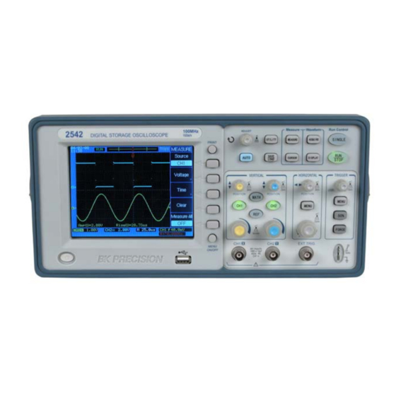
Models 2534, 2540 & 2542
Version 1.02
General Safety Summary
General Safety Summary
Review the following safety precautions to avoid injury and prevent
damage to this product or any products connected to it. To avoid potential
hazards, use this product only as specified.
Only qualified personnel should perform service procedures.
To Avoid Fire or Personal Injury
Use Proper Power Cord. Use only the power cord specified for this
product and certified for the country of use.
Connect and Disconnect Properly. Do not connect or disconnect probes
or test leads while they are connected to a voltage source.
Ground the Product. This product is grounded through the grounding
conductor of the power cord. To avoid electric shock, the grounding
conductor must be connected to earth ground. Before making connections
to the input or output terminals of the product, ensure that the product is
properly grounded.
Connect the Probe Properly. The probe ground lead is at ground
potential. Do not connect the ground lead to an elevated voltage.
Observe All Terminal Ratings. To avoid fire or shock hazard, observe
all ratings and marking on the product. Consult the product manual for
further ratings information before making connections to the product.
Do Not Operate Without Covers. Do not operate this product with
covers or panels removed.
Avoid Exposed Circuitry. Do not touch exposed connections and
components when power is present.
Do Not Operate With Suspected Failures. If you suspect there is
damage to this product, have it inspected by qualified service personnel.
Advertisement
Table of Contents

Subscribe to Our Youtube Channel
Related Manuals for BK Precision 2540


Summary of Contents for BK Precision 2540
- Page 1 Digital Storage Oscilloscopes Connect and Disconnect Properly. Do not connect or disconnect probes Models 2534, 2540 & 2542 or test leads while they are connected to a voltage source. Ground the Product. This product is grounded through the grounding conductor of the power cord.
- Page 2 General Safety Summary General Safety Summary Do Not Operate in Wet/Damp Conditions. Do Not Operate in an Explosive Atmosphere. Keep Product Surfaces Clean and Dry. Symbols and Terms on the Product. Protective Ground (Earth) Terminal. CAUTION. Refer to user manual. Caution indicates a hazard to property including this product...
-
Page 3: Table Of Contents
Contents Contents Capture a Single-Shot Signal......... 131 Contents Reduce the Random Noise on a Signal ....... 133 Contents ..................5 Trigger on a Video Signal ..........135 Getting Started...............7 PASS/FAIL Measurement..........138 Inspect package content............7 Waveform Recorder ............140 Front Panel ................8 Cursor Measurements............. -
Page 4: Getting Started
Five softkeys are located along the Verify that you received the following items: right side of the display screen. Oscilloscope The following figure shows the front panel of the 2534/2540 Two high performance 150MHz oscilloscope probes series oscilloscopes. Power cord... - Page 5 Getting Started Getting Started PRINT key Perform automated measurements waveform Press this key to print the current display to a USB mass parameters. storage device. ACQUIRE AUTO key The ACQUIRE menu lets you set the oscilloscope to When you press the AUTO key, the oscilloscope will acquire waveforms in Normal, Peak Detect, or Average quickly determine which channels are active and mode and lets you select Real Time or Equivalent...
- Page 6 Getting Started Getting Started Press the RUN/STOP key again to stop acquiring data. contract or expand relative to the ground reference level. The RUN/STOP key will be red. Now you may examine There is one vertical scale control knob for each channel. the acquired waveform by panning and zooming.
-
Page 7: Rear Panel
Getting Started Getting Started Rear panel Use these two probe compensation terminals to match each probe’s characteristics to the oscilloscope channel to which it is connected. 11. External trigger input This is the external trigger input BNC connector. 12. Channel input BNC This is the channel’s input BNC connector. -
Page 8: Interpreting The Display
Getting Started Getting Started record line color corresponds to the selected waveform color. Interpreting the display The trigger position icon shows the trigger location within The oscilloscope display contains channel acquisition the record. information, setup information, measurement results, and soft The trigger position icon shows the trigger location in the keys for setting up measurement parameters. -
Page 9: Basic Operation
Using Autoset Perform this adjustment to match your probe to the input The 2534 & 2540 series digital storage oscilloscopes provide channel. This should be done whenever you attach a passive the Autoset function which sets the vertical, horizontal, and probe for the first time to any input channel. -
Page 10: Vertical Controls
Basic Operation Basic Operation To undo the effects of Autoset, press the Undo Autoset softkey in the AUTO menu before pressing any other key. Vertical Controls This is useful when you have unintentionally pressed the AUTO key or do not like the settings Autoset has selected and want to return to your previous settings. -
Page 11: Ch1, Ch2 Menu
Basic Operation Basic Operation the voltage difference between the vertical center of the size. When coarse is selected, the vertical scale knob display and the ground level( ). changes the channel scale in a 1-2-5 step sequence. Press the small vertical position knob above the channel key ... - Page 12 Basic Operation Basic Operation Press the channel key CH1, then press the Coupling softkey Press the channel key CH1, then press the Coupling softkey to select DC coupling mode. to select GND coupling mode. DC coupling passes both AC and DC components of the GND mode blocks both AC and DC components of the input input signal.
- Page 13 Basic Operation Basic Operation Bandwidth Limit When Bandwidth limit is on, the maximum bandwidth for the Press the channel key CH1, then press the BW Limit softkey channel is approximately 20 MHz. For waveforms with to turn the bandwidth limit on for the selected channel 1. BW frequencies below this, turning bandwidth limit on removes Limit on mode blocks the high frequency components over unwanted high frequency noise from the waveform.
- Page 14 Basic Operation Basic Operation Probe Attenuation Setting Digital Filter Probes are available with various attenuation factors which Press the channel key CH1, then press the Digital Filter affect the vertical scale of the signal. You can manually select softkey to display the FILTER-CH1 menu.
- Page 15 Basic Operation Basic Operation Vertical Scale Turn the large vertical scale knob below the channel key to set the scale factor for the channel. The channel scale factor value is displayed in the bottom left portion of the display. Press CH1→...
- Page 16 Basic Operation Basic Operation Vertical Invert Press CH1→ More 1/2 → Invert to turn Invert on or off. When Invert is turned on, the voltage values of the displayed waveform are inverted. Invert affects how a channel is displayed, but does not affect triggering.
- Page 17 Basic Operation Basic Operation MATH Functions Press the softkey More ½ to display the MATH menu page Dual Waveform Calculation 2/2. Press the MATH channel key to turn on the MATH menu Softkey Options Description page1/2. Add A and B Softkey Options Description...
- Page 18 Basic Operation Basic Operation For example, we select the A+B math function, select CH1 as Press the MATH key to turn on the MATH menu page 1/2, the Source A, and select CH2 as the Source B, then we will and then press the Operate softkey to select FFT.
- Page 19 Basic Operation Basic Operation Press the softkey More 1/2 to display the FFT menu page For example, we select CH1 as the source for the FFT, select 2/2. the rectangular window, set the vertical scale to dBV RMS, and then we will get an FFT waveform similar to the following Softkey Options...
-
Page 20: Ref Function
Basic Operation Basic Operation Press the softkey More 1/2 to display REF menu page 2/2. REF Function You might make measurement on a known good system, save the result to internal memory or to a USB mass storage Softkey Options Description... -
Page 21: Horizontal Controls
Basic Operation Basic Operation Press REF→ Internal Storage →Save to save the waveform of the Source channel as the reference waveform to internal Horizontal Controls memory. Use the horizontal controls to adjust the time base, adjust the trigger location, and to examine waveform details more closely. - Page 22 The horizontal scale factor can be set in a 1-2.5-5 sequence (2534) or in a 1-2-5 sequence (2540/2542). Press the horizontal scale control knob to toggle between Main and Delayed horizontal mode.
- Page 23 Basic Operation Basic Operation Press the horizontal MENU key and then press the Main Press the softkey More 1/2 to display the HORIZONTAL softkey to select the main horizontal mode. menu page 2/2. Options Description Softkey Set the holdoff time Holdoff between two triggers.
- Page 24 Basic Operation Basic Operation Delayed Horizontal Mode Delayed horizontal mode is an expanded version of main mode. When Delayed mode is selected, the display divides in half. The top half of the display shows the normal waveform and bottom half displays the delayed waveform. The Delayed waveform is a magnified portion of the normal waveform.
- Page 25 Basic Operation Basic Operation X-Y Horizontal Mode X-Y mode changes the display from a volts-versus-time display to a volts-versus-volts display. The time base is turned off. The CH1 signal is plotted on the X axis and CH2 signal is plotted on the Y axis. You can use X-Y mode to compare the frequency and phase relationships between two signals.
- Page 26 Basic Operation Basic Operation Roll Horizontal Mode Roll mode causes the waveform to move slowly across the screen from right to left. It only operates on time base settings of 500 ms/div or slower. If the current time base setting is faster than the 500 ms/div limit, it will be set to 500ms/div when Roll mode is selected.
- Page 27 Basic Operation Basic Operation Holdoff Function Holdoff sets the amount of time that the oscilloscope will wait before rearming the trigger circuit. You can use the holdoff function to stabilize the display of complex waveforms. With the holdoff function, you can synchronize triggers. The oscilloscope will trigger on one edge of the waveform, and ignore further edges until the holdoff time is up.
-
Page 28: Trigger Controls
Basic Operation Basic Operation Trigger Controls Trigger Control MENU key The trigger controls determine when the oscilloscope starts Press the trigger control MENU key to show the TRIGGER to acquire and display the waveform. When a trigger is found, menu and then press the Type softkey to select Edge, Pulse the oscilloscope will acquire sufficent data to display the or Video. - Page 29 Basic Operation Basic Operation Trigger Level Control the pre-trigger buffer will contain the events that occurred just Use the trigger level control knob to adjust the trigger level. before the trigger. If no trigger is found, the oscilloscope This is the voltage level on the trigger waveform that causes generates a trigger and displays the data as though a trigger a trigger event.
- Page 30 Basic Operation Basic Operation In either Auto or Normal mode, the trigger may be missed. This is because the oscilloscope will not recognize a trigger event until the pre-trigger buffer is full. Softkey Options Description Video Video triggering Video Trigger Type Edge...
- Page 31 Basic Operation Basic Operation Note: The trigger level control is unavailable when Video type is selected. The following figures show the video waveforms triggered on odd fields and line 6. Edge Trigger Use edge triggering to trigger on the rising or falling edge of the input signal at the trigger threshold.
- Page 32 Basic Operation Basic Operation Pulse Width Trigger Press the trigger control MENU key to display the TRIGGER Pulse width triggering sets the oscilloscope to trigger on a positive or negative pulse of a specified width from 20ns to Softkey Options Description...
- Page 33 Basic Operation Basic Operation Press the trigger control MENU key to display the TRIGGER Press the trigger control MENU key to display the TRIGGER menu, press the Type softkey to select Pulse trigger, and menu, then press the Type softkey to select Pulse trigger. then press the More 1/2 softkey to display TRIGGER menu Softkey Options...
-
Page 34: Acquire Menu
Basic Operation Basic Operation ACQUIRE Menu Softkey Options Description Press the ACQUIRE menu key to show the ACQUIRE menu. Normal Normal acquisition. Average Average Mode waveforms. Peak detect Peak Detect acquisition. Equivalent Equivalent sampling. Sampling Real Time Real time sampling. ---- Select Record menu. - Page 35 Basic Operation Basic Operation Press the Mode softkey to select the Average mode. Connect a sine wave signal to the CH1 channel, press ACQUIRE → Mode to select Average mode. Turn the Entry Softkey Options Description knob to set the number of averages to 16. The following two Normal Normal acquisition.
- Page 36 Basic Operation Basic Operation Waveform recorder The waveform recorder can record input waveforms in a sequence of frames originating from channel 1 or channel 2, with a maximum acquisition depth of 1000 frames of 4k data points each. The time interval between each frame is adjustable from 1ms –...
- Page 37 Basic Operation Basic Operation Set the time interval between captured Play back the record waveform sequence (menu 1 of 2 Interval frames. <1ms Press ACQUIRE → Record to show the RECORD menu. – 1000s> Press the Mode softkey to select the Play Back function. Set the number of Softkey Options...
- Page 38 Basic Operation Basic Operation Play back the record waveform sequence (menu 2 of 2) Save/Recall the recorded waveform Press ACQUIRE → Record to show the RECORD menu. Press ACQUIRE → Record to show the RECORD menu. Press the Mode softkey to select the Save/Recall function. Softkey Options Description...
-
Page 39: Utility Menu
Basic Operation Basic Operation Exit the waveform recorder Press the Mode softkey to select the OFF option and return UTILITY Menu to the ACQUIRE menu. Press the UTILITY menu key to show the UTILITY menu. Softkey Options Description Record Record the waveform Play back... - Page 40 Basic Operation Basic Operation Press the UTILITY key to display the UTILITY menu page I/O Setup 1/2. Press UTILITY → I/O Setup to display the I/O SETUP menu. Softkey Options Description Softkey Options Description I/O Setup ---- Select I/O SETUP menu USB Slave Select USB Print ----...
- Page 41 Basic Operation Basic Operation System Setup Print Setup Press UTILITY → System Setup to display the SYSTEM Press UTILITY → Print Setup to display the PRINT menu. menu. Press the Print to softkey to select File. Softkey Options Description Softkey Options...
- Page 42 Basic Operation Basic Operation Press Date&Time softkey display Service DATE&TIME menu. Press UTILITY → Service to display the Service menu. Softkey Options Description Softkey Options Description Date & time display on Display system Display Date & time display off information: Model, System...
- Page 43 Basic Operation Basic Operation Press UTILITY → Service to display the Service menu, then press the System Info softkey to display the system Pass/Fail Mask test The Mask Test function monitors waveform changes by. If information, such as Model, Serial number, Power up times, the input signal is within the mask threshold, a PASS verdict Software version and a list of installed modules.
- Page 44 Basic Operation Basic Operation Press More 1/2 to display the PASS/FAIL menu 2/2. Press UTILITY → Pass/Fail → Setup Mask to display the MASK menu 1/2. Softkey Options Description Softkey Options Description Display P/F information Set the mask’s Turn Display P/F Display X Mask...
- Page 45 Basic Operation Basic Operation Press More 1/2 to display the MASK menu 2/2. Self-Calibration To maximize the measurement accuracy, it is recoomended Softkey Options Description to perform a self-calibration. Store the PASS/FAIL Internal Self-calibration uses internally-generated signals to calibrate ---- tolerance mask...
-
Page 46: Measure Menu
Basic Operation Basic Operation Note: Warm up the oscilloscope for at least 30 minutes Press the MEASURE key to display the MEASURE menu. before performing self-calibration. Softkey Options Description MEASURE Menu Measure CH1 Source Measure CH2 Select the Voltage Voltage ---- measurement menu. - Page 47 Basic Operation Basic Operation Voltage Measurements Press the More 1/4 softkey to display the VOLTAGE menu Press MEASURE → Voltage to display the VOLTAGE menu page 2/4. page 1/4. Softkey Options Description Softkey Options Description Measures the flattop The Peak-Peak value is voltage (average value) ----...
- Page 48 Basic Operation Basic Operation Press the More 2/4 softkey to display the VOLTAGE menu Press the More 3/4 softkey to display the VOLTAGE menu page 3/4. page 4/4. Softkey Options Description Softkey Options Description The Cycle Avg value is Return to the MEASURE ---- the sum of the samples...
- Page 49 Basic Operation Basic Operation Time Measurements Press More 1/5 softkey to display the TIME menu page 2/5. Press MEASURE → Time to display the TIME menu page Softkey Options Description 1/5. +Width is the time Softkey Options Description between the 50% +Width ----...
- Page 50 Basic Operation Basic Operation Measures the delay Press the More 2/5 softkey to display the TIME menu page between 2 waveforms 3/5. using the time between ---- Delay Softkey Options Description the first falling edge of Measures the delay CH1 and the first rising edge of CH2.
- Page 51 Basic Operation Basic Operation X at Min is the X axis value Press the More 3/5 softkey to display the TIME menu page (i.e., time) referred to the 4/5. trigger point at the first Softkey Options Description displayed occurrence of the X at Min ---- Phase 1→2 is the time in...
- Page 52 Basic Operation Basic Operation Press the Clear softkey to clear all displayed measurement Automatic Measurement Procedure parameter. Press MEASURE → Measure All to turn on Auto Measurements. Up to 20 measurements of the current Note: Up to three parameters can be displayed at the channel are displayed at the center of the screen.
-
Page 53: Save/Load Menu
Basic Operation Basic Operation Measurement definitions SAVE/LOAD Menu The following figure shows the voltage measurement points. SAVE/LOAD MENU key Press the SAVE/LOAD key to display the SAVE/LOAD menu. The following figure shows the time measurement points. Softkey Options Description Internal Display the INTERNAL... - Page 54 Basic Operation Basic Operation Internal Storage Press SAVE/LOAD→Internal Storage→Storage type to Press SAVE/LOAD→Internal Storage→Storage type to display the INTERNAL menu and select Setups storage type. display the INTERNAL menu and select Waveforms storage Softkey Options Description type. Waveform file format Storage Waveforms Softkey...
- Page 55 Basic Operation Basic Operation External Storage Press SAVE/LOAD→External Storage→New to display the Press SAVE/LOAD→External Storage to display the New menu. EXTERNAL menu. Softkey Options Description Softkey Options Description ---- Display the New File menu. New File Create a new file or folder in Display the New Folder ---- ----...
- Page 56 Basic Operation Basic Operation Press SAVE/LOAD→External Storage→New→New Foler Press SAVE/LOAD→External Storage→New→New File to to display the New Folder menu. display the New File menu. Softkey Options Description Softkey Options Description Enter the selected Enter Setups Save as setup files ---- character and go to the Character...
- Page 57 Basic Operation Basic Operation Press SAVE/LOAD→External Storage→Rename to display Press SAVE/LOAD→External Storage→Delete to display the Rename menu. the Delete menu. Softkey Options Description Softkey Options Description Enter the selected Confirm the deletion of Enter ---- ---- character and go to the the selected file or folder.
- Page 58 Basic Operation Basic Operation Finally, the message “Restart to complete updating” will Firmware Update be displayed to remind you to restart (power cycle) the The oscilloscope firmware can be conveniently updated via instrument. the front panel USB host interface. If the software update failed, repeat the above procedures to Press SAVE/LOAD→External Storage to display the update again.
-
Page 59: Cursor Menu
Basic Operation Basic Operation Manual Cursor Mode CURSOR Menu In manual cursor mode, you can move the cursors to You can measure waveform parameters using the cursors. measure the voltage or time on the selected waveform. Cursors are horizontal and vertical markers that indicate Press CURSOR→Mode to display the CURSOR menu and X-axis values (usually time) and Y-axis (usually voltage) on a select the Manual mode. - Page 60 Basic Operation Basic Operation Press CURSOR→Mode to display the CURSOR menu and Track Cursor Mode In the track mode, the screen displays two cross hair cursors. select the Manual mode. Press the Type softkey to select Time measurement. The cross hair of the cursor is positioned on the waveform automatically.
- Page 61 Basic Operation Basic Operation Auto Cursor Mode Press CURSOR→Mode to display the CURSOR menu and The Auto mode cursors are displayed only when the auto select the Track mode. measurement function is enabled. The oscilloscope displays Softkey Options Description auto cursors...
-
Page 62: Display Menu
Basic Operation Basic Operation Press the DISPLAY menu key to display the DISPLAY menu DISPLAY Menu page 1/2. Softkey Options Description Vector mode draws a line Vector between adjacent sample Type points in the waveform. Dot mode displays only Dots the sample points. -
Page 63: Run Controls
Basic Operation Basic Operation Press More 1/2 softkey to display the DISPLAY menu page RUN Controls 2/2. Softkey Options Description The scope updates the waveform without erasing Persist previously-displayed waveforms. Turn persistence function Press the softkey to Clear ---- erase the previous Persistence... - Page 64 Basic Operation Basic Operation RUN/STOP key be green. When the trigger mode is set to Normal mode, the display will not update until a trigger is found. If the trigger mode is set to Auto mode, the oscilloscope looks for a trigger, and if no trigger is found, it will be triggered automatically and the input signal(s) will be displayed immediately.
-
Page 65: Application Examples
Application Examples Application Examples Press the MEASURE key to display the MEASURE menu. 3. Application Examples Press the Voltage softkey to display the VOLTAGE menu. This section presents 7 typical application examples. These Press the Amplitude softkey to measure the amplitude. examples highlight the features of the oscilloscope and give The amplitude value will be displayed at the bottom of you ideas on how to solve your own test problems. -
Page 66: Capture A Single-Shot Signal
Application Examples Application Examples Press the SINGLE key to start the search for the trigger event. The SINGLE key is illuminated in orange Capture a Single-Shot Signal When trigger condition is met, the captured waveform is displayed, the SINGLE key is not lit, and the RUN/STOP A digital storage oscilloscope can easily capture an key is illuminated in red. -
Page 67: Reduce The Random Noise On A Signal
Application Examples Application Examples Press the Trigger MENU key to display the TRIGGER menu. Reduce the Random Noise on a Signal Press the Type softkey to select Edge trigger type. Press the Coupling to select HF Reject or LF Reject If the test signal is noisy, you can set up the oscilloscope to coupling mode to reduce the noise from the trigger reduce the noise on the displayed waveform. -
Page 68: Trigger On A Video Signal
Application Examples Application Examples Trigger on a Video Signal The video trigger can be used to capture standard video signals. The trigger circuit detects the vertical and horizontal intervals of the waveform and produces triggers based on the video trigger settings you have selected. Trigger on Odd or Even Fields of the Video Signal Press the Trigger MENU key to display the TRIGGER menu. -
Page 69: Pass/Fail Measurement
Application Examples Application Examples PASS/FAIL Measurement The oscilloscope measures and compares the input signal with a predefined Pass/Fail mask. If the input signal is within the mask threshold, a PASS verdict will be generated. If the input signal lies outside the threshold, a FAIL verdict will be generated. -
Page 70: Waveform Recorder
Application Examples Application Examples Press the More 1/2 softkey to display the PASS/FAIL menu page 2/2. Waveform Recorder Press the Msg Display softkey to display the Pass/Fail The waveform recorder lets you monitor and analyze long measurement results on the top left corner of the screen. term signal behavior by recording data continuously over long Press the Output softkey to set how the results will be periods of time then playing it back for post acquisition... - Page 71 Application Examples Application Examples Press the Operate softkey to playback the waveform. Perform the following steps to playback the waveforms. Press the ACQUIRE key to display the ACQUIRE menu. Press the RECORD softkey to display the RECORD menu. Press the Mode softkey to select Play back mode. Press the Play Mode softkey to select mode.
-
Page 72: Cursor Measurements
Application Examples Application Examples Perforxm the following steps to save or recall the waveform recorded. Cursor Measurements Press the ACQUIRE key to display the ACQUIRE menu. You can use the cursors to quickly take time and voltage Press the RECORD softkey to display the RECORD measurements on a waveform. - Page 73 Application Examples Application Examples Perform the following steps to make a voltage measurement Measure the frequency and amplitude of an FFT signal on a waveform. Perform the following steps to take frequency measurements. Press the CURSOR key to display the CURSOR menu. Press the MATH key to display the Math menu.
- Page 74 Application Examples Application Examples Press the CURSOR key to display the CURSOR menu. Press the Mode softkey to select the Manual mode. Measure the Phase Difference Between Two Signals of Press the Source softkey to select FFT. the Same Frequency under X-Y Display Mode. Press the Type softkey to select the Voltage type.
- Page 75 Application Examples The ∆Y displayed in the softkey area is the voltage difference D (or 2B) between Y1 and Y2. Press the Y1--/ Y2— softkey or press the entry knob to select the Y1 cursor. Rotate the entry knob to move the Y1 cursor to the upper intersection of the signal and the Y axis.
-
Page 76: System Message And General Problems
System Message and General Problems System Message and General Problems Empty storage memory: This message will be displayed when you try to load a file which does not exist from the 4. System Message and internal memory. Unrecognized file: This message will be displayed when General Problems you try to load a file which cannot be recognized by the oscilloscope. -
Page 77: General Problems
System Message and General Problems System Message and General Problems Incompatible file: This message will be displayed when the update software is not compatible with the model type. General Problems Load error: This message will be displayed when you fail to load a file from the internal or external memory. - Page 78 System Message and General Problems Try using HF Reject or LF Reject to reduce the noise of the trigger signal. If the amplitude is not identical with the actual voltage: Check that the attenuation factor of the probe corresponds to the attenuation factor set in the channel menu.
-
Page 79: Specifications And Characteristics
CAT II, 400V Bandwidth 100 MHz: 2542 150 ps between two channels with the same Differential delay scale and coupling settings 5.83 ns: 2534, 2540 Calculated rise time 3.50 ns: 2542 (=0.35/bandwidth) Coupling AC, DC, GND BW Limit 20 MHz selectable Vertical sensitivity 2mV/div –... - Page 80 Source CH1, CH2, EXT, EXT/5, AC Line, Alternating. 2.5 ns/div to 50 s/div (2534) Modes Auto, Normal, Single Time base range 2 ns/div to 50 s/div (2540, 2542) Coupling DC, AC, LF-Reject, HF-Reject Modes Main, Delayed, Roll, and X-Y Type...
-
Page 81: Acquisition System
Acquisition system Trigger mode Positive pulse , Negative pulse Max. real-time 400 MSa/s: 2534 Pulse Width Range 20ns to 10s sample rate 1 GSa/s: 2540, 2542 Max. equivalent 40 GSa/s: 2534 sample rate 50 GSa/s: 2540, 2542 Memory Depth 4000 points... - Page 82 Specifications Specifications Display system Power and environmental requirments Display 5.7 inch (145cm) diagonal STN LCD. Line voltage 99V to 242VAC Resolution 240 vertical by 320 horizontal pixels Line frequency 47Hz to 440Hz Color 256 VGA colours Power consumption Less than 50VA Brightness Adjustable...
-
Page 83: Appendix A: Service And Warranty Information
Specifications Specifications Limited Two‐Year Warranty Appendix A: Service and B&K Precision Corp. warrants to the original purchaser that its products Warranty Information and the component parts thereof, will be free from defects in workmanship and materials for a period of one year from date of purchase. - Page 84 Specifications Specifications 22820 Savi Ranch Parkway Yorba Linda, CA 92887 www.bkprecision.com © 2008 B&K Precision Corp. Printed in China ...
Need help?
Do you have a question about the 2540 and is the answer not in the manual?
Questions and answers