Table of Contents
Advertisement
Quick Links
Advertisement
Table of Contents

Related Manuals for BK Precision 2522C


Summary of Contents for BK Precision 2522C
- Page 1 INSTRUCTION MANUAL Model 2522C 20 MHz DIGITAL STORAGE/ANALOG OSCILLOSCOPE...
-
Page 2: Test Instrument Safety
TEST INSTRUMENT SAFETY WARNING Normal use of test equipment exposes you to a certain amount of danger from electrical shock because testing must often be performed where exposed high voltage is present. An electrical shock causing 10 milliamps of current to pass through the heart will stop most human heartbeats. -
Page 3: Table Of Contents
TABLE OF CONTENTS TEST INSTRUMENT SAFETY......................2 TABLE OF CONTENTS ........................3 FEATURES ............................4 SPECIFICATIONS ..........................6 CONTROLS AND INDICATORS ...................... 8 GENERAL FUNCTION CONTROLS ......................8 VERTICAL CONTROLS ..........................8 HORIZONTAL CONTROLS........................10 TRIGGERING CONTROLS ........................ -
Page 4: Features
FEATURES LOW COST, HIGH PERFORMANCE DUAL TRACE FEATURES Dual Trace B&K Precision’s Model 2522C is one of the lowest cost digital storage oscilloscopes in the industry, yet it includes all Model 2522C has two vertical input channels for dis- the basic features needed by most technicians and engineers. playing two waveforms simultaneously. - Page 5 F E A T U R E S T R I G G E R I N G F E A T U R E S Variable Holdoff Trigger inhibit period after end of sweep adjustable. Permits Two Trigger Modes stable observation of complex pulse trains.
-
Page 6: Specifications
SPECIFICATIONS HORIZONTAL AMPLIFIER (Input through channel 1 input) Type: 6-inch rectangular with integral graticule, P31 phosphor. X Y mode: CH 1 = X axis. Display Area: 8 x 10 div (1 div = 1 cm). CH2 = Y axis. Accelerating Voltage: 2 kV. Sensitivity: Same as vertical channel 2. - Page 7 Trigger Sensitivity: USB Host Interface 1.0 div (internal) Save screen image to USB flash drive ≥0.5 Vp-p (external) 30 Hz – 20 MHz OTHER SPECIFICATIONS TV-V: 1.0 div (internal) Cal/Probe Compensation Voltage: 0.5 V p-p ± 3% square wave, 1 ≥0.5 Vp-p (external) kHz nominal.
-
Page 8: Controls And Indicators
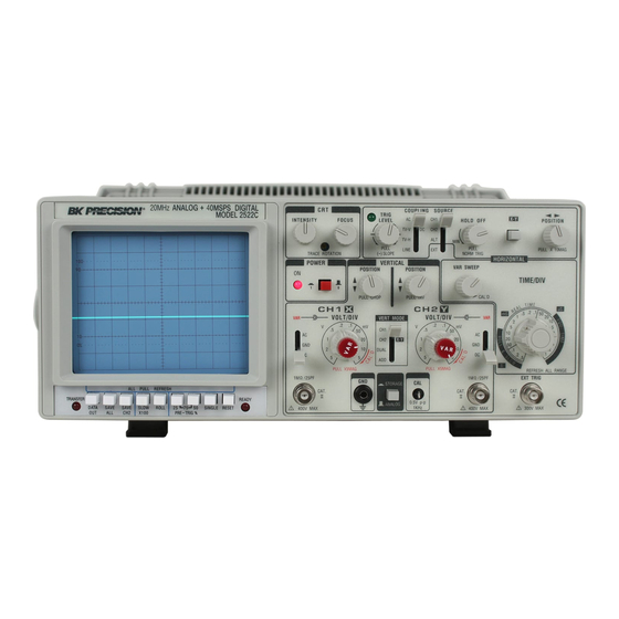
CONTROLS AND INDICATORS Fig. 1. Model 2522C Controls and Indicators. X-Y: used in conjunction with the X-Y control and GENERAL FUNCTION CONTROLS 1. ON Indicator. Lights when oscilloscope is “on”. Trigger SOURCE switch to enable X-Y display mode. 2. POWER Pushbutton. Turns oscilloscope “on” and DUAL: “off”. - Page 9 Fig. 2. Rear Panel Controls and Indicators. PULL CHOP: Direct coupling of channel 1 input signal; both ac When this switch is pulled out in the dual-trace mode, the and dc components of signal produce vertical de- channel 1 and channel 2 sweeps are chopped and displayed flection.
-
Page 10: Horizontal Controls
PULL X5 MAG: PULL NORM TRIG: When pulled out, increases vertical sensitivity by a When pushed in, selects AUTOmatic triggering factor of five. Effectively provides two extra sensitivity mode. In this mode, the oscilloscope generates settings: 2 mV/div and 1 mV/div. In X-Y mode, increases sweep (free runs) in absence of an adequate trigger;... - Page 11 HOLDOFF: Rotation adjusts holdoff time (trigger inhibit period TRIGger LEVEL: Trigger level adjustment; determines the point on beyond sweep duration). When control is rotated the triggering waveform where the sweep is trig- fully counterclockwise, the holdoff period is MIN- gered. Rotation in the (–) direction (counterclock- inum (normal).
-
Page 12: Digital Storage Controls
C O N T R O L S A N D I N D I C A T O R S sweep. PULL (—) SLOPE: 35. READY Indicator. Lights when the RESET switch readies Two-position push-pull switch. The “in” position the scope for single sweep, and goes out when trigger signal selects a positive-going slope and the “out”... -
Page 13: Operating Instructions
OPERATING INSTRUCTIONS SAFETY PRECAUTIONS EQUIPMENT PROTECTION PRECAUTIONS W A R N I N G The following precautions will help avoid The following precautions must be observed damage to the oscilloscope. to help prevent electric shock. 1. When the oscilloscope is used to make measurements in 1. -
Page 14: Operating Tips
OPERATING INSTRUCTIONS A trace should appear on the CRT. Adjust the trace brightness OPERATING TIPS with the INTENSITY control, and the trace sharpness with The following recommendations will help obtain the best the FOCUS control. performance from the oscilloscope. 1. Always use the probe ground clips for best results, SINGLE TRACE DISPLAY attached to a circuit ground point near the point of measurement. -
Page 15: Triggering
5. In the CHOP sweep mode (PULL CHOP switch pulled form observation until other controls can be properly set. out), the sweep is chopped (switched) between channel 1 Once the controls are set, operation is often switched back and channel 2. Using CHOP, one channel does not have to the normal triggering mode, since it is more sensitive. - Page 16 mode (VERT MODE set to DUAL), and with TIME BASE Control alternate sweep only (PULL CHOP not engaged). Set the Time Base TIME/DIV control to display the desired 3. In the EXT position, the signal applied to the EXT number of cycles of the waveform. If there are too many cycles TRIG jack becomes the trigger source.
-
Page 17: Magnified Sweep Operation
OPERATING INSTRUCTIONS At most points of measurement, a composite video signal is of the () polarity, that is, the sync pulses are negative and the MAGNIFIED SWEEP OPERATION video is positive. In this case, use () SLOPE. If the waveform Since merely shortening the sweep time to magnify a portion is taken at a circuit point where the video wave-form is inverted, of an observed waveform can result in the desired portion... - Page 18 4. Once a waveform is digitized, it can be stored in Single-sweep mode can be used in the presence of very rapidly long-term memory by pressing the SAVE ALL or occurring events, even continuous waveforms if desired. In that SAVE CH2 switches. The SAVE CH2 switch case, the period between pushing the RE-SET switch and the immediately stores the channel 2 waveform.
- Page 19 OPERATING INSTRUCTIONS 3. The rolling display can be frozen at any time by pressing the SAVE CH2 or SAVE ALL switches (as discussed in the section on “Digitizing Repetitive Waveforms”). N O T E ROLL mode cannot be used on sweep speeds greater than 10 ms/div.
-
Page 20: Maintenance
MAINTENANCE PERIODIC ADJUSTMENTS W A R N I N G Probe compensation and trace rotation adjustments should be The following instructions are for use by checked periodically and adjusted if required. These procedures are qualified service personnel only. To given below. avoid electrical shock, do not perform any servicing other than contained in P r o b e C o m p e n s a t i o n... -
Page 21: Calibration Check
MAINTENANCE CALIBRATION CHECK INSTRUMENT REPAIR SERVICE A general check of calibration accuracy may be made by Because of the specialized skills and test equipment required displaying the output of the CAL terminal on the screen. for instrument repair and calibration, many customers prefer This terminal provides a square wave of 0.5 V p-p. -
Page 22: Appendix I
APPENDIX I IMPORTANT CONSIDERATIONS FOR RISE TIME AND FALL TIME MEASUREMENTS Error in Observed Measurement Calculated Measurements The observed rise time (or fall time) as seen on the For observed rise times of less than 54 ns, the pulse rise time should CRT is actually the cascaded rise time of the pulse being be calculated to eliminate the error introduced by the cascaded measured and the oscilloscope’s own risetime. -
Page 23: Appendix Ii
APPENDIX II UNIQUE CHARACTERISTICS OF DIGITAL STORAGE OSCILLSCOPES Digital Storage Oscilloscopes (DSO’s) use a digital sampling obviously incorrect. This occurs because the DSO is technique to convert analog input signals to a series of digital taking one sample every 0.1 ms and a 10 kHz signal has words that can be stored in memory. - Page 24 Intentionally left blank...
-
Page 25: Service Information
SERVICE INFORMATION Warranty Service: Please go the support and service section on our website www.bkprecision.com to obtain a RMA #. Return the product in the original packaging with proof of purchase to the address below. Clearly state on the RMA the performance problem and return any leads, probes, connectors and accessories that you are using with the device. - Page 26 22820 Savi Ranch Parkway Yorba Linda, CA 92887 www.bkprecision.com © 2009 B&K Precision Corp. 481-315-9-001 Printed in Taiwan...
Need help?
Do you have a question about the 2522C and is the answer not in the manual?
Questions and answers