
Subscribe to Our Youtube Channel
Related Manuals for BK Precision 2120C


Summary of Contents for BK Precision 2120C
- Page 1 GlobalTestSupply www. .com Find Quality Products Online at: sales@GlobalTestSupply.com...
-
Page 2: Test Instrument Safety
TEST INSTRUMENT SAFETY WARNING Normal use of test equipment exposes you to a certain amount of danger from electrical shock because testing must often be performed where exposed high voltage is present. An electrical shock causing 10 milliamps of current to pass through the heart will stop most human heartbeats. Voltage as low as 35 volts dc or ac rms should be considered dangerous and hazardous since it can produce a lethal current under certain conditions. - Page 3 GlobalTestSupply www. .com Find Quality Products Online at: sales@GlobalTestSupply.com...
-
Page 4: Table Of Contents
TABLE OF CONTENTS Page Page TEST INSTRUMENT SAFETY ..inside front cover OPERATING INSTRUCTIONS (Continued) X−Y Operation ......15 FEATURES . - Page 5 GlobalTestSupply www. .com Find Quality Products Online at: sales@GlobalTestSupply.com...
-
Page 6: Features
FEATURES AUTO Sweep Built-in Probe Adjust Square Wave Selectable AUTO sweep provides sweep without trig- A 2 V p-p, 1 kHz square wave generator permits probe ger input, automatically reverts to triggered sweep compensation adjustment. operation when adequate trigger is applied. Component Test Function (Model 2125C &... - Page 7 GlobalTestSupply www. .com Find Quality Products Online at: sales@GlobalTestSupply.com...
-
Page 8: Specifications
≥0.5 Vp-p (external) Input Impedance: Approximately 50 kΩ. 100 Hz – 40 MHz (2125C) Usable Frequency Range: DC to 5 MHz. 100 Hz – 30 MHz (2120C) Maximum Input Voltage: 30 V (dc + ac peak). Norm: 1.5 div (internal) ≥0.5 Vp-p (external) -
Page 9: General Function Controls
GlobalTestSupply www. .com Find Quality Products Online at: sales@GlobalTestSupply.com... - Page 10 GlobalTestSupply www. .com Find Quality Products Online at: sales@GlobalTestSupply.com...
-
Page 11: Controls And Indicators
23. Main Time Base TIME/DIV Control. Provides step 29. 2120C Only. X-Y Switch. Used with the VERTical selection of sweep rate for the main time base. When MODE switch and Trigger SOURCE switch to se- the VARiable Sweep control is set to CAL, sweep rate lect X-Y operating mode. -
Page 12: Triggering Controls
CONTROLS AND INDICATORS NORM: TRIGGERING CONTROLS Selects normal triggered sweep operation. A sweep 30. HOLDOFF/PULL CHOP Control. is generated only when an adequate trigger signal is HOLDOFF: present. Rotation adjusts holdoff time (trigger inhibit period TV-V: beyond sweep duration). When control is rotated Used for triggering from television vertical sync fully counterclockwise, the holdoff period is MIN- pulses. -
Page 13: Operating Instructions
OPERATING INSTRUCTIONS NOTE EQUIPMENT PROTECTION All operating instructions in this chapter PRECAUTIONS apply equally to all Models except for the sections on “Delayed Sweep Operation" and “Component Test”, which apply only to the Models 2125C & 2160C. Other The following precautions will help avoid differences are noted when necessary. -
Page 14: Operating Tips
OPERATING INSTRUCTIONS 2. Press the red POWER pushbutton (Model 2120C & OPERATING TIPS 2160C), or rotate the POWER control clockwise The following recommendations will help obtain the best “away from "OFF" (Model 2125C & 2160C). performance from the oscilloscope. 3. A trace should appear on the CRT. Adjust the trace 1. -
Page 15: Triggering
OPERATING INSTRUCTIONS 3. To view both waveforms simultaneously, set the TRIGGERING VERTical MODE switch to DUAL and select either These Oscilloscopes provide versatility in sync ALT (alternate) or CHOP with the PULL CHOP triggering for ability to obtain a stable, jitter-free display switch. - Page 16 OPERATING INSTRUCTIONS the control is centered, the threshold level is set at the Trigger SOURCE Switch approximate average of the signal used as the triggering The trigger SOURCE switch (CH 1, CH 2, etc.) selects source. Proper adjustment of this control usually synchro- the signal to be used as the sync trigger.
-
Page 17: Magnified Sweep Operation
1. On Models 2125C & 2160C, set the SWEEP MODE adjust the oscilloscope for a normal display. switch to the X−Y position. On the Model 2120C, de- 2. Set the Sweep Mode switch to the MIX position. The -press the X−Y switch. On both models, set the Trigger display will show the main sweep on the left portion Source and VERTical MODE switches to X−Y. -
Page 18: Component Test Operation
OPERATING INSTRUCTIONS component test function can be used to view the signatures of resistors, capacitors, inductors, diodes, and other semi- Delayed Sweep conductor devices. Devices may be analyzed in-circuit or out-of-circuit and combinations of two or more devices may be displayed simultaneously. Each component produces a different signature and the components can be analyzed as outlined below. - Page 19 OPERATING INSTRUCTIONS Fig. 6. Typical Resistive Signatures. GlobalTestSupply www. .com Find Quality Products Online at: sales@GlobalTestSupply.com...
- Page 20 OPERATING INSTRUCTIONS Inductors Like capacitance, a purely inductive impedance produces a signature that is an ellipse or circle and value is determined by the size and shape of the ellipse. A very high inductance causes the ellipse to flatten out horizontally and a very low inductance causes the ellipse to flatten out vertically.
- Page 21 OPERATING INSTRUCTIONS Semiconductors Purely semiconductor devices (such as diodes and transis- tors) will produce signatures with straight lines and bends. Typical diode junctions produce a single bend with a hori- zontal and vertical line as shown in Fig. 9. Zener diodes produce a double bend with two vertical and one horizontal line as shown in Fig.
-
Page 22: Maintenance
MAINTENANCE PERIODIC ADJUSTMENTS WARNING Probe compensation and trace rotation adjustments should be checked periodically and adjusted if required. The following instructions are for use by These procedures are given below. qualified service personnel only. To avoid electrical shock, do not perform any serv- Probe Compensation icing other than contained in the operat- 1. -
Page 23: Calibration Check
MAINTENANCE CALIBRATION CHECK INSTRUMENT REPAIR SERVICE A general check of calibration accuracy may be made by Because of the specialized skills and test equipment re- displaying the output of the CAL terminal on the screen. quired for instrument repair and calibration, many custom- This terminal provides a square wave of 2 V p-p. -
Page 24: Appendix
X10 magni- When a probe is used, its rise time is also cascaded in square fication. For the Models 2125C and 2120C, this sweep rate law addition. Thus the probe rating should be considerably is 10 ns/div. -
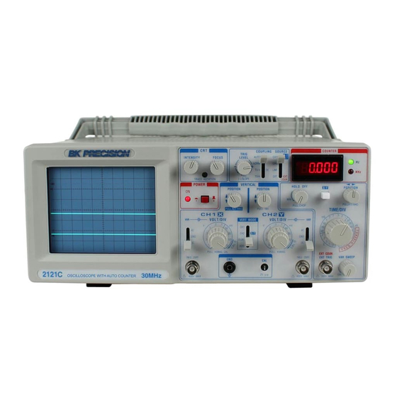
Page 25: 2121C Specifications & Operating Instruction
GlobalTestSupply www. .com Find Quality Products Online at: sales@GlobalTestSupply.com... - Page 26 DISPLASY RESOLUTION: NOTE: If input signal is not synchronized correctly on CRT display Frequency counter Auto select from 0.001Hz to 1KHz depending may have incorrect measurements. on the frequency. To check power line frequency with the 2121C MAX COUNTER RANGE: set Trigger SOURCE switch to LINE position.
- Page 27 GlobalTestSupply www. .com Find Quality Products Online at: sales@GlobalTestSupply.com...
-
Page 28: Service Information
GlobalTestSupply www. .com Find Quality Products Online at: sales@GlobalTestSupply.com... - Page 29 INFORMATION One of the best tutorials on oscilloscopes in the industry. Valuable to those with little knowledge of oscilloscopes as well as the experienced technician or engineer who wishes to refresh their memory or explore new uses for oscilloscopes. GlobalTestSupply www.
- Page 30 ©201 4 B +K P rec is ion C orp. v072914 Pr inted in Taiwan GlobalTestSupply www. .com Find Quality Products Online at: sales@GlobalTestSupply.com...
Need help?
Do you have a question about the 2120C and is the answer not in the manual?
Questions and answers