
Related Manuals for BK Precision 2522B


Summary of Contents for BK Precision 2522B
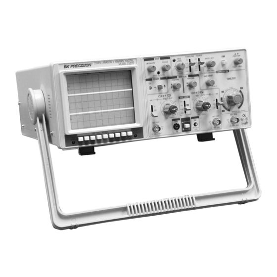
- Page 1 BK PRECISION ® INSTRUCTION MANUAL MODEL 2522B 20 MHz DIGITAL STORAGE/ANALOG OSCILLOSCOPE BK PRECISION ®...
-
Page 2: Test Instrument Safety
TEST INSTRUMENT SAFETY WARNING Normal use of test equipment exposes you to a certain amount of danger from electrical shock because testing must often be performed where exposed high voltage is present. An electrical shock causing 10 milliamps of current to pass through the heart will stop most human heartbeats. Voltage as low as 35 volts dc or ac rms should be considered dangerous and hazardous since it can produce a lethal current under certain conditions. - Page 3 Instruction Manual BK PRECISION ® Model 2522B 20 MHz Digital Storage/Analog Oscilloscope ©2000 B+K Precision Corp. This symbol on oscilloscope means “refer to instruction manual for further precautionary information”. This symbol appears in the manual where the corresponding information is given.
-
Page 4: Table Of Contents
TABLE OF CONTENTS Page Page TEST INSTRUMENT SAFETY ..inside front cover OPERATING INSTRUCTIONS (Continued) Digital Storage Operation ..... 15 FEATURES . -
Page 5: Features
FEATURES LOW COST, HIGH PERFORMANCE DUAL TRACE FEATURES B+K Precision’s Model 2522B is one of the lowest cost Dual Trace digital storage oscilloscopes in the industry, yet it includes Model 2522B has two vertical input channels for dis- all the basic features needed by most technicians and engi- playing two waveforms simultaneously. - Page 6 FEATURES Variable Holdoff TRIGGERING FEATURES Trigger inhibit period after end of sweep adjustable. Two Trigger Modes Permits stable observation of complex pulse trains. Selectable normal (triggered) or automatic sweep modes. OTHER FEATURES Triggered Sweep X−Y Operation Sweep remains at rest unless adequate trigger signal is Channel 1 can be applied as horizontal deflection applied.
-
Page 7: Specifications
SPECIFICATIONS HORIZONTAL AMPLIFIER Type: 6-inch rectangular with integral graticule, P31 (Input through channel 1 input) phosphor. X−Y mode: Display Area: 8 x 10 div (1 div = 1 cm). CH 1 = X axis. CH 2 = Y axis. Accelerating Voltage: 2 kV. Sensitivity: Same as vertical channel 2. - Page 8 SPECIFICATIONS Trigger Sensitivity: PLOT OUTPUT 1.0 div (internal) Analog output of the stored display. ≥0.5 Vp-p (external) CH 1 and CH 2 Outputs: 30 Hz – 30 MHz Selected by PLOT switch. Output via CH1 OUTPUT TV-V: 1.0 div (internal) and CH2 OUTPUT jacks on rear panel.
-
Page 9: Controls And Indicators
CONTROLS AND INDICATORS Fig. 1. Model 2522B Controls and Indicators. X-Y: used in conjunction with the X-Y control and GENERAL FUNCTION CONTROLS Trigger SOURCE switch to enable X-Y display 1. ON Indicator. Lights when oscilloscope is “on”. mode. 2. POWER Pushbutton. Turns oscilloscope “on” and DUAL: “off”. - Page 10 CONTROLS AND INDICATORS PLOT OUTPUT (ANALOG) OUTPUT OUTPUT DOWN OUTPUT LINE VOLTAGE SLELCTOR SELECTOR LINE VOLTAGE FUSE WARNING SERIALNO’ Fig. 2. Rear Panel Controls and Indicators. PULL CHOP: Direct coupling of channel 1 input signal; both ac When this switch is pulled out in the dual-trace and dc components of signal produce vertical de- mode, the channel 1 and channel 2 sweeps are flection.
-
Page 11: Horizontal Controls
On the 17. CH2 (Y) Input Jack. Vertical input for channel 2. Model 2522B, automatic triggering is applicable to Y-axis input for X-Y operation. both the main sweep and delayed sweep. -
Page 12: Digital Storage Controls
CONTROLS AND INDICATORS PULL (—) SLOPE: operation. A suitable trigger signal arriving after press- ing the RESET switch initiates the single sweep. Two-position push-pull switch. The “in” position selects a positive-going slope and the “out” position 35. READY Indicator. Lights when the RESET switch selects a negative-going slope as triggering point for readies the scope for single sweep, and goes out when main sweep. -
Page 13: Operating Instructions
OPERATING INSTRUCTIONS SAFETY PRECAUTIONS EQUIPMENT PROTECTION PRECAUTIONS WARNING The following precautions must be ob- The following precautions will help avoid served to help prevent electric shock. damage to the oscilloscope. 1. When the oscilloscope is used to make measurements 1. Never allow a small spot of high brilliance to remain in equipment that contains high voltage, there is al- stationary on the screen for more than a few seconds. -
Page 14: Operating Tips
OPERATING INSTRUCTIONS 3. A trace should appear on the CRT. Adjust the trace OPERATING TIPS brightness with the INTENSITY control, and the The following recommendations will help obtain the best trace sharpness with the FOCUS control. performance from the oscilloscope. 1. -
Page 15: Triggering
Trigger SOURCE Switch TRIGGERING The trigger SOURCE switch (CH 1, CH 2, etc.) selects The Model 2522B Oscilloscope provides versatility in the signal to be used as the sync trigger. sync triggering for ability to obtain a stable, jitter-free dis- play in single-trace, or dual-trace operation. - Page 16 OPERATING INSTRUCTIONS mode (VERT MODE set to DUAL), and with alter- TIME BASE Control nate sweep only (PULL CHOP not engaged). Set the Time Base TIME/DIV control to display the 3. In the EXT position, the signal applied to the EXT desired number of cycles of the waveform.
-
Page 17: Magnified Sweep Operation
An X−Y OPERATION analog/digital unit such as the Model 2522B allows the user X−Y operation permits the oscilloscope to perform many to set up sensitivity, sweep, and triggering in a familiar measurements not possible with conventional sweep opera- analog setting, and then switch to the digital mode. - Page 18 “pre-trigger” information, that is, events occurring before these higher sweep speeds cannot be used the arrival of a trigger event. On the Model 2522B, pre-trig- for capture of one-time events. Equivalent ger operation is available in single-sweep mode by setting time sampling is discussed in detail in Ap- the PRE TRIG switches.
-
Page 19: Applications Guidebook
PEN DOWN output is at a constant TTL Using Plotter Output high. The Model 2522B oscilloscope provides facilities for Engaging the SLOW X100 switch slows driving an analog plotter. The following instructions explain the plot output by a factor of 100 on the how to output a waveform;... -
Page 20: Maintenance
MAINTENANCE PERIODIC ADJUSTMENTS WARNING Probe compensation and trace rotation adjustments should be checked periodically and adjusted if required. The following instructions are for use by These procedures are given below. qualified service personnel only. To avoid electrical shock, do not perform any serv- Probe Compensation icing other than contained in the operat- 1. -
Page 21: Calibration Check
MAINTENANCE CALIBRATION CHECK INSTRUMENT REPAIR SERVICE A general check of calibration accuracy may be made by Because of the specialized skills and test equipment re- displaying the output of the CAL terminal on the screen. quired for instrument repair and calibration, many custom- This terminal provides a square wave of 0.5 V p-p. -
Page 22: Important Considerations For Rise Time And Fall Time Measurements
Direct Measurements For fast rise time measurements which approach the limits The Model 2522B has a rated rise time of 18 ns. Thus, of measurement, direct connection via 50 Ω coaxial cable pulse rise times of about 54 ns or greater can be measured and 50 Ω... -
Page 23: Unique Characteristics Of Digital Storage Oscilloscopes
APPENDIX II UNIQUE CHARACTERISTICS OF DIGITAL STORAGE OSCILLSCOPES Digital Storage Oscilloscopes (DSO’s) use a digital sam- obviously incorrect. This occurs because the DSO is pling technique to convert analog input signals to a series of taking one sample every 0.1 ms and a 10 kHz signal digital words that can be stored in memory. -
Page 24: Service Information
SERVICE INFORMATION Warranty Service: Please return the product in the original packaging with dated proof of purchase to the address below. Clearly state in writing the performance problem and return any leads, connectors, and accessories that you are using with the device. -
Page 25: Limited Warranty
LIMITED WARRANTY B+K Precision Corp. warrants to the original purchaser that its product, and the component parts thereof, will be free from defects in workmanship and materials for a period of three years from the date of purchase. B+K Precision Corp. will, without charge, repair or replace, at its option, defective product or component parts upon delivery to an authorized B+K Precision service contractor or the factory service department, accompanied by proof of the purchase date in the form of a sales receipt. - Page 26 INFORMATION One of the best tutorials on oscilloscopes in the industry. Valuable to those with little knowledge of oscilloscopes as well as the experienced technician or engineer who wishes to refresh their memory or explore new uses for oscilloscopes. Download your FREE copy from our Web site www.bkprecision.com...
- Page 27 ® 1031 Segovia Circle, Placentia, CA 92870 © 2000 B+K Precision Corp. 481-315-9-001 Printed in Taiwan...
Need help?
Do you have a question about the 2522B and is the answer not in the manual?
Questions and answers