Table of Contents
Advertisement
This service information is designed for experienced repair technicians only and is not designed for use by the general public.
It does not contain warnings or cautions to advise non-techical individuals of potential dangers in attempting to service a product.
Products powered by electricity should be serviced or repaired only by experienced professional technicians. Any attempt to service
or repair the product or products dealt with in this service information by anyone else could result in serious injury or death.
CONTENTS
--------------------------------------------------------
------------------------------------------------------
------------------------------------------
-----------------------------------------------------
--------------------------------------------------
-------------------------------------------------
-----------------------------------------------
---------------------------------------------------
-----------------------------------
R
R
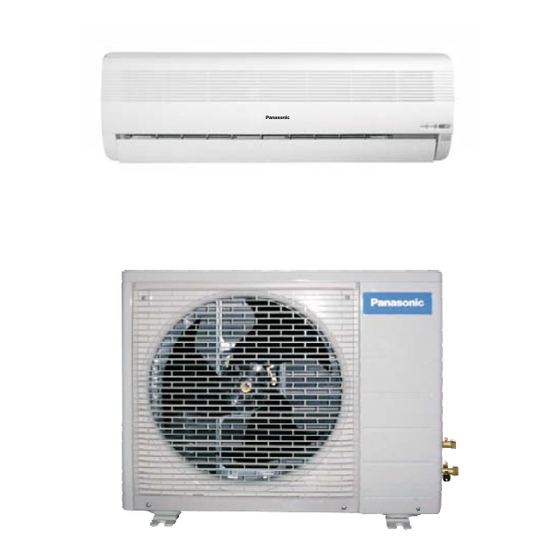
CS/CU-PA7DKD
CS/CU-PC7DKD
CS/CU-PA9DKD
CS/CU-PC9DKD
WARNING
Page
2
3
6
14
16
17
19
21
35
C
(GMAC) All rights reserved. Unauthorized copying
and distribution is violation of law.
Order No. GMAC0504036C3
Room Air Conditioners
-----------------------------------------------------
--------------------------------------
----------------------------------------
--------------------------------------------------
--------------------------------------------------
-----------------------------------------
--------------------------------------------------
-----------------------------------------
--------------------------------------
Guangzhou Matsushita Air Conditioner Co., Ltd.
Page
49
56
59
61
64
65
66
67
68
Advertisement
Table of Contents


Need help?
Do you have a question about the cs-pa7dkd and is the answer not in the manual?
Questions and answers