Table of Contents
Advertisement
Quick Links
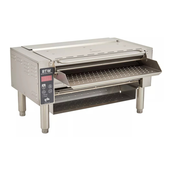
Rolling Tortilla Warmer
Owner's Manual
Models
RTW14E and RTW20E [patent pending]
This manual includes material related to installation,
use , cleaning, and care. Exploded view[s], as well
as any available parts list[s] and wiring diagram[s]
pertaining to the unit[s] covered by this manual are
also included.
This manual must be read and understood by all
persons using or installing this appliance. Contact
your Star dealer if you have any questions concerning
installation, use, or maintenance of this equipment.
DO NOT DISCARD THIS MANUAL.
RTW14E
2M-Z19213 - Rev D - 06.2016
Advertisement
Table of Contents

Subscribe to Our Youtube Channel
Related Manuals for Star RTW14E


Summary of Contents for Star RTW14E
- Page 1 This manual must be read and understood by all persons using or installing this appliance. Contact your Star dealer if you have any questions concerning installation, use, or maintenance of this equipment. DO NOT DISCARD THIS MANUAL. RTW14E...
- Page 2 LIMITED EQUIPMENT WARRANTY All workmanship and material in Star products have a one (1) year limited warranty on parts and labor in the United States and Canada unless otherwise noted below. Such warranty is limited to the original purchaser only and shall be eff ective from the date the equipment is placed in service.
-
Page 3: Table Of Contents
TABLE OF CONTENTS Warranty General Information and Installation 1–2 Daily Operation 3–4 Cleaning Maintenance Wiring Diagram Exploded Views 8–13 Parts List 14–17 Wall Mount Installation 18–19 Specifications Factory Settings Adjustment... - Page 4 NOTES...
- Page 5 Due to periodic changes in designs, methods, procedures, policies, and regulations, the specifications contained in this sheet are subject to change without notice. Star reserves the right to change product specifications and design without notice. Such revisions do not entitle the buyer to corresponding changes, improvements, additions or replacements for previously purchased equipment.
-
Page 6: General Information And Installation
Before making any electrical connection to this unit, check that the power supply is adequate for the voltage, amperage, and requirements stated on the rating plate. RTW14E units will require a NEMA 5-15R receptacle. RTW20E units will require a NEMA 6-15R receptacle. Make certain to disconnect the unit from the power source before installing or removing any parts. -
Page 7: Daily Operation
DAILY OPERATION CERTAIN SURFACES ARE EXTREMELY HOT DURING OPERATION AND CARE SHOULD BE TAKEN WHILE USING THIS UNIT. THIS UNIT IS DESIGNED TO WARM DRY, FLEXIBLE PRODUCTS ONLY. DO NOT ATTEMPT TO RUN WET OR LOOSE MATERIAL THROUGH IT. ELECTRONIC CONTROLS BUTTONS (PRIMARY USES) •... - Page 8 UNITS OF TEMPERATURE SELECTION With the machine OFF hold the “SET/TEMP” and “▲/CLEAN” buttons. Once the menu pops up hit the “SET/TEMP” button to scroll through until “SCALE” is displayed on the screen. At this point hit the “▲/CLEAN” button to toggle between Fahrenheit and Celsius. Continue scrolling through using the “SET/TEMP”...
-
Page 9: Cleaning
Remove the inlet tray and wash using warm water and mild detergent. iv. Wipe the drum using a damp cloth. v. Reassemble the parts previously removed. Wipe with damp cloth. Clean using warm water and detergent. Clean using warm water and detergent. RTW14E... -
Page 10: Maintenance
DISCONNECT UNIT FROM POWER SOURCE i. Remove the screws holding the right side panel and remove the panel. ii. Use an extreme pressure synthetic chain lubricant rated up to at least 400°F (204°C) [Star part number 1L-Z12397] and liberally lubricate the chain and sprockets. -
Page 11: Wiring Diagram
WIRING DIAGRAM POWER MUST BE REMOVED FROM THE UNIT BEFORE ATTEMPTING REPAIR OR SERVICE. MAKE CERTAIN TO CHECK ALL CONNECTIONS THOROUGHLY BEFORE RESTORING POWER TO THE UNIT. THE BELOW INFORMATION IS FROM WIRING DIAGRAM WD-Z20778. Please review the following information before proceeding with any electrical diagnosis or repair. i. -
Page 12: Exploded Views
CENTER DRUM, ROLLERS, AND ELEMENTS RTW14E-120 pictured SCRAPER ASSEMBLY RTW14E-120 pictured... - Page 13 RIGHT SIDE [CHAIN DRIVE] RTW14E-120 pictured 23 34...
- Page 14 LEFT SIDE RTW14E-120 pictured 10 6...
- Page 15 REAR [1] RTW14E-120 pictured...
- Page 16 REAR [2] RTW14E-120 pictured...
- Page 17 CENTER SECTION RTW20E-208 pictured...
-
Page 18: Parts List
2A-Z5942 leg, 4-inch RTW20E 2A-307628 leg, 6-inch ALL RTW 2A-Z10076 spacer, steel RTW14E 2A-Z18673 scraper support rod, RTW14E RTW20E 2A-Z18701 scraper support rod, RTW20E RTW14E-120 RTW14E-230 2C-200004 screw, 6-32 x 0.375 [phillips head] 8, 9, 10, 11, 12 RTW20E-208 ALL RTW... - Page 19 ALL RTW 2C-Z5192 rivet, 0.1875-inch RTW20E 2A-Z19909 standoff, 0.219 x 0.035 x 0.500 RTW14E 2C-Z9632 screw, #10-32 x 0.5-inch RTW20E RTW14E 2D-Z20318 top roller, RTW14E RTW20E 2D-Z19995 top roller, RTW20E RTW14E 2D-Z20320 drum, RTW14E RTW20E 2D-Z20250 drum, RTW20E ALL RTW 2E-Z12427...
- Page 20 ALL RTW D6-Z20383 idler bracket ALL RTW 2P-Z8392 sprocket, idler RTW14E 2C-Z20417 screw, #10-32 x 0.75-inch RTW20E RTW14E D6-RTW041 inlet tray assembly, RTW14E RTW20E D6-RTW035 inlet tray assembly, RTW20E RTW14E D6-Z20496 inlet tray, RTW14E RTW20E D6-Z20314 inlet tray, RTW20E RTW14E D6-Z20497...
- Page 21 D6-Z20313 tortilla slide, RTW20E RTW14E D6-Z20534 top cover, RTW14E RTW20E D6-Z20308 top cover, RTW20E RTW14E D6-Z20535 top cover, rear RTW14E RTW20E D6-Z20309 top cover, rear RTW20E ALL RTW D6-Z20536 mount, gear motor ALL RTW D6-Z20537 cover panel, right side ALL RTW 2C-Z20722 screw, #10-24 x 0.375-inch...
-
Page 22: Wall Mount Installation
LAG SCREWS MUST BE INSTALLED INTO STUDS FOR SUPPORT OF THE RTW UNIT. FAILURE TO INSTALL IN STUDS COULD RESULT IN DAMAGE TO UNIT AND/OR HARM TO PERSONS OR PROPERTY. STAR IS NOT RESPONSIBLE FOR DAMAGE RELATED TO INCORRECT INSTALLATION OR FAULTY CONSTRUCTION. - Page 23 lag screws Step Three—Tighten mounting bolts. Once the bracket is properly positioned, tighten lag bolts down the rest of the way. Install truss screws in lower holes and tighten fully. truss screws Step Four—Finish installation. Place tortilla warmer into bracket as shown below. Align mounting holes on the bottom of unit with the holes in wall mount bracket.
-
Page 24: Specifications
13.9 in. 353 mm CLEARANCES Please allow at least ten [10] inches (254 mm) of space to open the top RTW14E is the model for cleaning if the unit is to remain used in these drawings. 5.8 in. 10 in. - Page 26 STAR MANUFACTURING INTERNATIONAL INC. Printed in the U.S.A. • 2M-Z19213 • Rev D • 06.2016 Specifications are subject to change without notice. 10 Sunnen Drive Saint Louis, Missouri 63143 • Telephone 800 264 7827 Fax 314 781 5445 • www.star-mfg.com...
Need help?
Do you have a question about the RTW14E and is the answer not in the manual?
Questions and answers