Table of Contents
Advertisement
Advertisement
Table of Contents

Related Manuals for Bowens XMS Studio Flash

Summary of Contents for Bowens XMS Studio Flash
- Page 1 XMS Studio Flash User Guide Bowens.co.uk...
- Page 2 page left intentionally blank...
- Page 3 In order to obtain the full benefit from your purchase, please take a few moments to familiarise yourself with this user manual. For more information about Bowens products or to find details of your nearest Bowens dealer, please visit the website.
-
Page 4: Table Of Contents
Table of Contents SAFET Y INSTRUCTIONS • Warning ......5 Safety precautions ......5 Environmental safety . -
Page 5: Safety Instructions
• Always study and understand this user guide and accompanying safety instructions before using this unit. • Make sure that the Bowens User Guide and Safety Instructions always accompany this unit. • Bowens products are intended for professional photographic use only and should not be used for any other purpose. - Page 6 Safety Instructions Environmental Safety • Do not place or use the unit where it could be exposed to moisture, dripping, splashing, extreme electromagnetic fields or in areas with flammable liquids, gases or dust. • Do not expose the unit to rapid temperature changes in humid conditions as this can lead to internal condensation.
-
Page 7: Xms
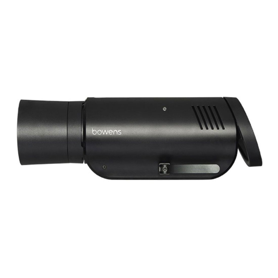
Protector Cap Reflector S-Mount Accessory Release Stand Mount Angle Adjustment Lever AC Input 3.5mm Jack Sync Power: On / Standby Menu Test / Open Flash 12 . Rotary Control Sync: Radio / Photocell Ready Indications: Beep / Dim Lamp: Prop / Free Photocell Display Handle... - Page 8 Quick Start Guide The following is a quick guide to the individual controls, display and functions. Unless specified all push buttons operate as follow: • Press the button briefly to toggle the related function On or Off. • Press and hold the button to cycle through the options for the function. •...
-
Page 9: Head Angle Adjustment
Quick Start Guide Stand Mounting Pull the Angle Adjustment Lever away from the main unit and extract the Stand Mount from the recess. Push the Angle Adjustment Lever back in place to lock the Stand Mount in position. Loosen the Stand Mount Thumb Screw on the Stand Mount and place the unit onto a support stand. -
Page 10: Flash Output Setting
Operation Flash Output Setting Use the Rotary Control to change the flash output level. The current flash energy is shown on the digital display in digital f-stops. All flash settings are related to the max setting (100%) which is shown as 10. Turn the Rotary Control clockwise to increase the energy level in 1/10 f-stop increments, and counter-clockwise to decrease. -
Page 11: Test And Ready Indication
Operation Modelling Light Free Setting continued. While in FREE set mode, use the turn dial to change the FREE level. While an adjustment is being made it will stay in the FREE SET mode. Adjust the turn-dial clockwise to increase the FREE level in 1/10 f-stop increments, and counter-clockwise to decrease. - Page 12 Operation Ready Indication Setting continued. To turn off the READY indications, briefly press the READY Button. Both the indicators will be turned off. Briefly press the READY button again to turn the ready indications back on. Photocell The XMS photocell allows the unit to be triggered by another flash unit. The photocell is specially designed to work under studio light conditions.
-
Page 13: Sync Source Setting
Operation Sync Source Setting continued. To select the Pre-flash photocell, press and hold down the SYNC button until only the CELL Indicator is illuminated. The unit will be triggered by an infrared (IR) light pulse received from another flash unit or other pulsed light source but only after a pre-set number of flashes have been received in a pre-set time frame (see page 15). -
Page 14: User Options
User Options User Menu Use the MENU button to access various settings to allow function customisation of the unit. Review and Adjustment Select the required option by pressing the MENU button. Hold the MENU button down to advance quickly through the options. Release the button when the desired option is displayed. -
Page 15: Remote Channel (Ch)
User Options Pairing (Pr) This option allows the unit to be paired or un-paired with an XMSR as well as allowing all pairing associations to be cleared. Refer to the XMSR Radio Trigger and Remote Control section. Remote Channel (Ch) This allows selection of the radio remote channel for this unit. - Page 16 User Options Pre-Flash Number (Pn) continued: To exit the Auto mode if no flashes have been detected then either: Select a Pre-flash setting greater than 0. Choose another option and then allow the options display to time out. The Pre-flash value will be set to 1 (single main flash only). Press the TEST button to exit immediately.
- Page 17 User Options Controls Sounder (So) Use this option to select the beep sounder to ‘Off, Warnings only, Button clicks only, or Both’. Note that the sounder will still produce a ‘ready’ beep regardless of this setting if the ‘ready’ beep is enabled. Lamp Saver (LS) This feature can be used to automatically dim the lamp to a minimum after a period of inactivity.
- Page 18 User Options Power Switch State (PS) This option allows the last state of the Standby/Power switch to be remembered if power to the unit is suddenly lost. Set this option to 0 (Off) to always power up in Standby or 1 (On) to remember the last Power Switch state. When set to on and power is lost and then restored, the unit will continue to operate in the same state that it was in before the power was lost.
- Page 19 XMSR Radio Remote & Trigger General The built-in XMSR radio trigger and remote control system is designed to be secure and interference tolerant. It allows the unit to be triggered and most functions to be controlled remotely. Refer to the instructions for the XMSR Remote Control. To enable an XMS and a remote control to communicate they need to be ‘paired’...
- Page 20 XMSR Radio Remote & Trigger Pairing With a Master (Pr/nP): Pr=pair / nP=new pair Ensure both the XMSR and XMS units are switched on and in fairly close proximity so that the two displays can be seen. On the XMS unit press the MENU button until the display shows ‘Pr’ to indicate ‘Pairing’...
-
Page 21: Thermal Management
XMSR Radio Remote & Trigger Clearing All Pairing Associations (Pr/CP): Pr=pair / CP clear pairs The XMS can be cleared of associations with ALL XMSR remotes without needing a remote. This can be useful if the XMS was originally ‘paired’ with a remote that is no longer available. -
Page 22: Modelling Lamp Fitting
User Maintenance Modelling Lamp Fitting Before fitting or removing a modelling lamp, always ensure the power is switched off and remove the mains cable from the unit. Avoid touching the flashtube and glass envelope of the modelling bulb with bare fingers as this can leave grease on the glass which can shorten the life of the bulb. -
Page 23: Warning And Error Management
Warnings Warning and Error Management The XMS is fitted with a comprehensive monitoring system to detect any miss- operation. If the display shows a Warning or an Error code and it does not automatically clear itself in a reasonable time then switch the unit to standby and back on again to see if it then clears. -
Page 24: Radio Fault
Warnings OH indication continued: CONDITION STEPS TO RECTIFY Flash rate excessively fast: Reduce the flash rate and/or only flash at a fast rate in blocks with longer cooling periods in between. Fan not running or slow: Unit requires repair. OH does not clear: Unit requires repair. -
Page 25: Xms500
Specifications XMS500 Specifications Energy (Ws/J) Power Range (f-stops) Power Range (Ws/J) 7.8 - 500 Power Range (Fraction) 1/1 - 1/64 Flash Duration (t=0.5) f4.0 - f8.7 = 1/2480 - 1/5180 f8.8 - f10 = 1/3080 - 1/4000 Recycle Time Range @ 230V 50Hz 0.2 (min) - 1.0 (max) sec. - Page 26 Specifications Features common to all units Specifications Power Increments (f-stop) 1/10-stop or 1-stop Flash to flash consistency (f-stop) ±0.05 Nominal colour temperature 5600ºK Flash to flash colour temperature consistency +/-30ºK Multivoltage (fitted with appropriate rated modelling lamp) Nominal operating voltage ranges (V) 100V / 120V / 230V +/-10% Nominal operating mains frequencies (Hz) 50Hz / 60Hz +/-5%...
- Page 27 page left intentionally blank...
- Page 28 Bowens International Ltd. Gilberd Court, Colchester, Essex, CO4 9WN, UNITED KINGDOM. email: info@bowens.co.uk tel: +44(0)1206 832650 Bowens.co.uk BWL0845 XMS User Guide...
Need help?
Do you have a question about the XMS Studio Flash and is the answer not in the manual?
Questions and answers