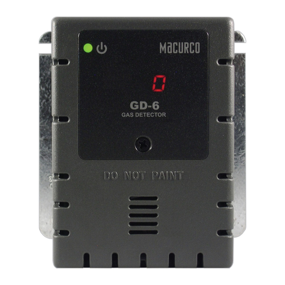
Macurco GD-6 User Instructions
Combustible gas detector, controller and transducer
Hide thumbs
Also See for GD-6:
- Operation manual (160 pages) ,
- Application manual (16 pages) ,
- User instructions (72 pages)

Related Manuals for Macurco GD-6


Summary of Contents for Macurco GD-6
- Page 1 Macurco GD-6 ™ Combustible Gas Detector, Controller and Transducer User Instructions Important: Keep these User Instructions for reference...
-
Page 2: Table Of Contents
Fan Minimum Runtime setting Fan Relay Latching setting Trouble Fan Setting 4-20mA Output setting On Board Diagnostics Sensor Poisons MAINTENANCE End-of-Life Signal Sensor Life Reset Cleaning Testing Operation Test Gas Test Quick Gas Test Field Calibration Procedure MACURCO GAS DETECTION PRODUCTS WARRANTY... -
Page 3: General Safety Information
Intended Use The Macurco GD-6 is a low voltage, dual relay Combustible Gas detector, controller and transducer. The GD-6 has selectable 4-20 mA output, buzzer and digital display options. It is an electronic detection system used to measure the concentration of Combustible Gas and provide feedback and automatic exhaust fan, louver or valve control to help reduce gas concentrations in parking garages, battery rooms or other commercial applications. -
Page 4: Use Instructions And Limitations
4-20 mA output. The GD-6 has a low maintenance long life (5+ years) pellistor sensor and optional gas test and calibration kits. The GD-6 is a low level meter... -
Page 5: Features
INSTALLATION AND OPERATING INSTRUCTIONS The following instructions are intended to serve as a guideline for the use of the Macurco GD-6 Combustible Gas Detector. It is not to be considered all-inclusive, nor is it intended to replace the policy and procedures for each facility. If you have any doubts about the... -
Page 6: Location
If the target gas is heavier than air; propane (LP), mount the GD-6 low on a wall or column (about one foot above the floor) in a central area where air movement is generally good. -
Page 7: Garage Diagram
The Fan Relay can be configured for latching or non-latching (default) when activated (when the gas concentration exceeds fan relay set point). Once latched in, power will need to be interrupted or the “TEST” button pressed to un-latch the relay condition. The Fan Relay will engage if the fan setting Combustible Gas concentration is exceeded for longer than the Fan Relay Delay time. -
Page 10: Alternate Alarm Panel
Power Up The GD-6 cycles through an internal self-test cycle for the first minute that it is powered. The unit will execute the test cycle any time power is dropped and reapplied (i.e. power failure). During the self-test cycle the unit will display the firmware version number, then count down from 60 to 0 (if the display setting is “On”) and finally go into normal operation. -
Page 11: Display Setting
Gas Selection To select the Gas Option, in normal mode, press the Next button once to display the current gas selection (mE is Methane, Pro is Propane and Hy is Hydrogen). Then press the Enter button twice to enter the selection menu. The currently selected gas will be shown on the display. -
Page 12: Buzzer Setting
Selecting Buzzer Option – “bUZ” To select the Buzzer Configuration, in normal mode, press the Next button twice to get to “Con” or the Configuration menu. Then press the Enter button to enter the Con menu. The fourth selection is the “bUZ” or Buzzer setting. Press Next three times to get to “bUZ” then press Enter. -
Page 13: Fan Minimum Runtime Setting
Onboard Diagnostics The GD-6 monitors all critical functions of the unit through software diagnostics that continuously test and verify unit operations. If a problem is found, the unit will switch to a fail-safe/error mode or trouble condition. . In this error mode, the Alarm relay will be activated, the 4-20 mA current loop will go to 24 mA, the unit will display the error code, the green status indicator LED light will flash and the buzzer will chirp intermittently. -
Page 14: Sensor Poisons
The GD-6 has a long life, non-replaceable catalytic bead sensor. Five (5) years after the GD-6 is installed the sensor end-of-life signal will be activated indicating that the GD-6 has reached the end of its typical usable life. The end-of-life signal will cause an error code t200 “Sensor expired”. -
Page 15: Cleaning
Operation Test Check that the green GD-6 status indicator LED light is illuminated continuously. If not, do not proceed with the tests. If the unit is in error mode contact your local representative or Macurco technical service representative for information on resolving the problem. - Page 16 The display progresses through the BUZ (Buzzer Test) Art (alarm relay test), Frt (fan relay test) then 42t (4-20 mA output test). Make sure that the settings are “on” or not disabled “diS”. During the first 10 seconds of the test cycle, the display will show BUZ and set off the audible buzzer The alarm relay will be closed, so any devices connected to that relay will be tested.
-
Page 17: Gas Test
General The GD-6 can be bump-tested or calibrated with the GD-6 Field Calibration Kit using Methane, Propane or Hydrogen gas, regulator and test hood, available through your local representative or from Macurco. Contents of the FCK GDM-FCK: Two Gas Cylinders, 10% LEL Methane gas in air, 20% LEL Methane in air, Gas regulator with two feet of plastic tubing, Humidifier and Gas test hood ... - Page 18 Turn on the regulator to start the gas flow and wait with the gas applied continuously. With the display function turned “On”, the GD-6 will show the current concentration of gas or “0” (zero) in clean air. When the gas concentration reaches the fan relay setting (5% LEL, for example) the display will flash back and forth between “FAn” and “5”.
- Page 19 Detector has 4-20 mA option set to “OFF”. Set 4-20 mA option to “On” and repeat the test. Remove the gas from the sensor. Re-assemble the GD-6 (make sure the LED is aligned with the hole on the front of the case).
-
Page 20: Field Calibration Procedure
The display option should be set to “On” and reading 0% LEL in clean air. With the GD-6 cover on, aim the lighter into the sensor grate area (under “DO NOT PAINT”) on the front cover and release the gas (without igniting the flame) for 1 second or less Wait for a few seconds. -
Page 21: Macurco Gas Detection Products Warranty
If there is proper pressure in the cylinder repeat steps 4 through 11. If the unit fails to calibrate twice contact Macurco Technical Assistance at 1-877-367-7891. Disassemble the cylinder and regulator. Re-assemble the GD-6 (make sure the LED is aligned with the hole in the front case). See Calibration Flowchart on the inside of the housing. - Page 22 MACURCO FIXED GAS DETECTION PRODUCTS LIMITED WARRANTY Macurco warrants the GD-6 gas detector will be free from defective materials and workmanship for a period of two (2) years from date of manufacture (indicated on the inside cover of the GD-6), provided it is maintained and used in accordance with Macurco instructions and/or recommendations.
Need help?
Do you have a question about the GD-6 and is the answer not in the manual?
Questions and answers