Table of Contents
Advertisement
Quick Links
Download this manual
See also:
Service Manual
Advertisement
Table of Contents

Related Manuals for Patton electronics 2500 Series


Summary of Contents for Patton electronics 2500 Series
- Page 1 USER MANUAL MODEL 2500 Series Models 2500, 2510, 2520 All-Rate CSU/DSU SALES OFFICE Part# 07M2500-C (301) 975-1000 Doc# 099021UC TECHNICAL SUPPORT Revised 3/13/96 (301) 975-1007...
-
Page 2: Table Of Contents
The Model 2500 Series has been tested and found to comply with the limits for a Class A... -
Page 3: Fcc Information
The telephone company may decide to temporarily discontinue your service if they believe your Model 2500 Series may cause harm to the telephone network. Whenever possible, they will contact you in advance. If you elect to do so, you have the right to file a complaint with the FCC. -
Page 4: Supported Applications
If the DTR signal on the RS-232 is active, then the RS-232 inputs are selected. Otherwise, the V.35 inputs are selected. If you choose, you may re-configure the Model 2500 Series for fixed V.35 or fixed RS-232 operation. To do this, follow the steps below: 1) Turn the power switch off. -
Page 5: Network Interface Connections
The Network Interface is an 8 position modular connector. Connect this port to the RJ-48S jack provided by the digital data service provider. If the Model 2500 Series is being used for private short haul communication, the twisted pair cable will connect to this port. See Appendix D for the pin assignments of this connector. - Page 6 Figure 2. Close up of DIP switches showing ON/OFF positions. 4.1.1 SWITCH SET SW1 The configuration switches on switch set SW1 allow you to specify Line Rate, Circuit Assurance, RTS, Character Length, Data Format and DSR Loop Status. Figure 3 (below) summarizes SW1 switch settings, including the factory defaults.
- Page 7 On Disabled Anti-Stream Timer Switch SW2-8 RTS/ Off Normal CTS Delay Figure 4. Summary of switch settings, showing factory defaults The Model 2500 Series includes a rate adapter that allows the unit SW2-1 SW2-2 SW2-3 DTE Rate 2.4 kbps 4.8 kbps 9.6 kbps...
-
Page 8: Configuration Using Software Switches
1) Connect the serial RS-232C port of the terminal to the modular EIA-561 control port on the front panel of the Model 2500 Series. To construct an RS-232 to EIA-561 patch cable, refer to the control port pinout diagram in Appendix D. - Page 9 4.2.1 USING THE SOFTWARE MENU SYSTEM The Model 2500 Series Menu System operates as follows: 1) All selections must be followed by [RETURN]. 2) To make a selection from any menu, enter the option number at the prompt and press [RETURN].
- Page 10 DTE equipment. This extra stop bit reduces the DTE’s effective data rate by a few percent to allow synchronization with the 56 kbps line speed. Set the Model 2500 Series for two stop bits by selecting “11 bit character length” in the Character Length Menu.
- Page 11 Choosing option 8 in the Software Switch Menu takes you to the DTE Loop Control Menu (below). The local and remote loopbacks on the Model 2500 Series can be controlled from the DTE interface by raising or lowering the LL and RL signals. To allow the DTE to control these loopbacks in this manner, enable this option.
- Page 12 • Internal (Master): To use the Model 2500 Series internal reference clock as the timing source, select item 1. Use internal timing in point-to- point applications where the Model 2500 Series is being used as a limited distance modem. (Set the far-end Model 2500 Series unit for looped timing as described below.)
-
Page 13: Operation
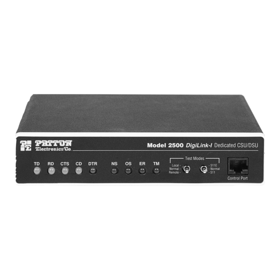
The Model 2500 Series is equipped with nine LED indicators that monitor the status of communication. Figure 5 (below) shows the location of the LEDs on the Model 2500 Series front panel. Note also the location of the test mode switches and RS-232 control port (used in Switched 56 dialing as well as software configuration). -
Page 14: Loopback Test Modes
5.3.1 LOCAL ANALOG LOOPBACK (LAL) The Local Analog Loopback (LAL) test checks the operation of the local Model 2500 Series. Any data sent to the local Model 2500 Series in this test mode will be echoed (returned) back to the user device. For example, characters typed on the keyboard of a terminal will appear on the terminal screen (see Figure 6, below). - Page 15 LAL Test Procedure Once LAL is activated, the Model 2500 Series transmit output is connected to its own receiver. The “Test” LED should be lit. Follow these steps to complete the test: 1) Verify that the data terminal equipment is operating properly and can be used for a test.
-
Page 16: The V.52 Ber Test Pattern Generator
(using one operator). The following example requires two operators–one to initiate and monitor the test at the local Model 2500 Series, and one at the remote Model 2500 Series. To use the V.52 BER test by itself, both operators should simultaneously follow these steps: (continued) 1) Locate the “511/511E”... -
Page 17: Switched 56 Dialing Commands (Models 2510 & 2520)
After dialing the number, the Model 2500 Series will display the message, “Dialing” and then display each number as it is dialed. The Model 2500 Series will then prompt the user to wait while the connection is made. One of the following messages will then be displayed to indicate the success or failure or the connection: •... -
Page 18: Appendix Aspecifications
2400 bps 15.1 14.2 APPENDIX B CABLE RECOMMENDATIONS The Patton Model 2500 Series operates at frequencies of 20kHz or less and has been performance tested by Patton technicians using twisted-pair cable with the following characteristics: Wire Gauge Capacitance 19 AWG 83nf/mi or 15.72 pf/ft. -
Page 19: Appendix C - Factory Replacement Parts And Accessories
APPENDIX C FACTORY REPLACEMENT PARTS AND ACCESSORIES Patton Model # Description 10-2500 ...DDS Cable, RJ48 - RJ48, 6 foot 10-561S...Control Port Cable, EIA-561, 6ft, shielded 12M-561 ...Adapter, EIA-561 to DB-25 Male 12F-561 ...Adapter, EIA-561 to DB-25 Female 082R2...Fuse 5x20mm, 200mA, 250V, Time-lag Little Fuse P/N 239.200 0805US ...American Power Cord 0805EUR...European Power Cord CEE 7... -
Page 20: Appendix Etransmitter Clock Source During Test Loops
(APPENDIX D - Continued) DB-25 CONNECTOR, TERMINAL INTERFACE Pin # Signal Frame Ground SGND (Signal Ground) LL (Local Loop) RL (Remote Loop) TM (Test Mode) CONTROL PORT INTERFACE 8 Position modular connector compliant with EIA-561. Pin # Signal Signal Ground RD (Output) TD (Input) APPENDIX E...