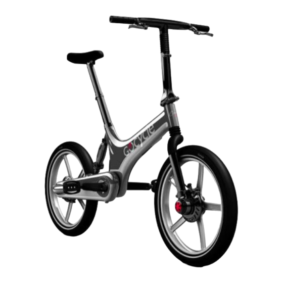
Gocycle G2 Assembly Manual
Hide thumbs
Also See for G2:
- Assembly manual (15 pages) ,
- Owner's manual (91 pages) ,
- Service document (23 pages)
Table of Contents
Advertisement
Quick Links
Advertisement
Table of Contents

Summary of Contents for Gocycle G2
- Page 1 : G2 K SSEMBLY UIDE ICKSTAND Version 2.0 Installation of the G2 Kickstand...
-
Page 2: Table Of Contents
Assembly Guide: G2 Kickstand 2013/14 ONTENTS Contents i Overview ......................1 1. Gocycle Model Identification ................1 2. Kickstand Assembly Parts List (For Frame Numbers <240000) ......2 Tool List <240000 ....................2 3. Battery Removal ..................... 3 4. Kickstand Preparation ..................6 5. -
Page 3: Overview
Assembly Guide: G2 Kickstand VERVIEW This assembly guide details installation of the G2 Kickstand for both 2013 and 2014 model Gocycles. If you have any questions, or require any further assistance, please contact techsupport@gocycle.com. OCYCLE ODEL DENTIFICATION 1.1. Locate the Gocycle unique frame number. -
Page 4: Kickstand Assembly Parts List (For Frame Numbers <240000)
Assembly Guide: G2 Kickstand ICKSTAND SSEMBLY ARTS RAME UMBERS <240000) To successfully complete the procedure you will require the following G2 Kickstand parts: Part Code Part Description Quantity 2181 Stand Rubber 2327 Kickstand Stud 2384 M8 SS Wave Spring 2385... -
Page 5: Battery Removal
Assembly Guide: G2 Kickstand ATTERY EMOVAL 3.1. For ease, invert the Gocycle so that it rests on its handlebars and saddle. Remove the PitstopWheels. WHEN INVERTING THE GOCYCLE, DO SO ON A SOFT, NON-MARKING SURFACE, E.G. CARPET, TO AVOID DAMAGE TO... - Page 6 Assembly Guide: G2 Kickstand 3.4. Remove both the black and red Anderson connectors from within the frame and unplug one at a time, as shown. 3.5. Locate the other Anderson connectors and unplug. 3.6. Ensure all cables are unplugged and none are trapped before continuing.
- Page 7 Assembly Guide: G2 Kickstand 3.8. Completely remove the battery from the frame. © Karbon Kinetics Limited. All Rights Reserved.
-
Page 8: Kickstand Preparation
Assembly Guide: G2 Kickstand ICKSTAND REPARATION 4.1. Inspect the stud location hole for any overspray of paint. If the hole is clear and free from paint, continue to step 5.1. 4.2. Affix tape to an 8mm drill bit positioned no more than 10mm from the tip. -
Page 9: Kickstand Installation
Assembly Guide: G2 Kickstand ICKSTAND NSTALLATION 5.1. Use the supplied stud installation wire and insert it through the stud locating hole. Leave a short length of wire protruding from the stud locating hole and a long length protruding from the rear of the frame, as shown. - Page 10 Thread the stud installation wire through the Stand Rubber (A) and install over the stud as shown. 5.5. Open the legs of the G2 Kickstand (E), as shown. 5.6. Thread the installation wire through the Kickstand body and install over the Kickstand Stud.
- Page 11 Assembly Guide: G2 Kickstand 5.8. Now install the M8 SS Wave Spring (C) over the stud as shown. 5.9. Install the M8 Thin Nut SS (D) over the stud as shown. 5.10. Finger-tighten the installed M8 nut onto the Kickstand stud.
- Page 12 Assembly Guide: G2 Kickstand 5.11. Insert the 3mm Allen key into the Kickstand Stud as shown. Use a 13mm spanner to tighten the nut. DO NOT TURN THE ALLEN KEY Note: Tighten the nut until the wave spring is flat and the Kickstand does not rotate side to side.
-
Page 13: Kickstand Assembly Parts List (For Frame Numbers >240000)
Assembly Guide: G2 Kickstand ICKSTAND SSEMBLY ARTS RAME UMBERS >240000) To successfully complete the procedure you will require the following G2 Kickstand parts: Part Code Part Description Quantity 2387 G2 Kickstand Assembly 2181 Stand plastic 2385 M8 Thin Nut SS >240000... -
Page 14: Kickstand Preparation
Assembly Guide: G2 Kickstand ICKSTAND REPARATION 7.1. Locate the Rubber Mounting Cap on the underside off the bottom bracket. 7.2. With your fingers, turn the Rubber Mounting Cap anticlockwise to unscrew. 7.3. Remove Rubber Mounting Cap. © Karbon Kinetics Limited. All Rights Reserved. -
Page 15: Kickstand Installation
Assembly Guide: G2 Kickstand ICKSTAND NSTALLATION 8.1. Open G2 Kick stand assembly legs part ‘A’. Align Stand Plastic part ‘B’ with G2 Kickstand Assembly Legs part ’A’. 8.2. Align Stand Plastic part ‘B’ and G2 Kickstand Assembly part ‘A’ with M8 Bolt. - Page 16 Assembly Guide: G2 Kickstand 8.3. Ensure the kickstand Legs bend towards the back wheel on assembly when in ‘open position’ as shown. 8.4. Locate the M8 nut (Part ‘C’) and thread on to the kitckstand bolt as shown. © Karbon Kinetics Limited. All Rights Reserved.
- Page 17 Assembly Guide: G2 Kickstand 8.5. Use a 13mm spanner to tighten the nut to a 20Nm torque. 8.6. Kickstand assembly complete. Note: If Kickstand Adjustment is required please refer to section 9. © Karbon Kinetics Limited. All Rights Reserved.
-
Page 18: Kickstand Adjustment
IMPORTANT NOTE: THE ASSEMBLY STEPS MUST BE CARRIED OUT IN ORDER. FAILING TO DO SO MAY RESULT IN DAMAGE TO THE GOCYCLE. If you have any further queries or comments, please contact Gocycle Technical Support: techsupport@gocycle.com © Karbon Kinetics Limited. All Rights Reserved.


Need help?
Do you have a question about the G2 and is the answer not in the manual?
Questions and answers