Chauvin Arnoux pel 102 User Manual
Power energy logger
Hide thumbs
Also See for pel 102:
- User manual (86 pages) ,
- Quick start manual (52 pages) ,
- User manual (70 pages)
Table of Contents
Advertisement
Quick Links
Advertisement
Table of Contents

Subscribe to Our Youtube Channel
Related Manuals for Chauvin Arnoux pel 102


Summary of Contents for Chauvin Arnoux pel 102
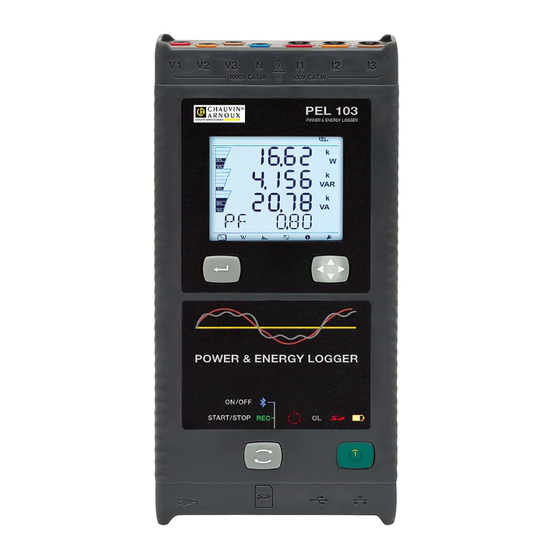
- Page 1 P E L 1 0 2 P E L 1 0 3 POWER ENERGY LOGGER User’s manual E N G L I S H...
- Page 2 Thank you for purchasing a Power & Energy Logger PEL102/103. To obtain the best service from your unit: „ read these operating instructions carefully, „ comply with the precautions for use. WARNING, risk of DANGER! The operator must refer to these instructions whenever this danger symbol appears. CAUTION! Risk of electric shock.
-
Page 3: Table Of Contents
CONTENTS 1. GETTING STARTED ................................4 1.1. Unpacking ...................................4 1.2. Charging the battery ..............................5 2. PRODUCT FEATURES ................................6 2.1. Description ..................................6 2.2. Front Panel Features ..............................7 2.3. Back Panel Features ..............................8 2.4. Lead Inputs ..................................8 2.5. Installation of the colour-coded markers ........................9 2.6. -
Page 4: Getting Started
Nous certifions que ce produit a été fabriqué conformément aux spécifications techniques de constuction applicables. We certify that this product is manufactured in accordance with applicable constructing specifications. 907 009 119 - 02/03 QUICK START GUIDE OF THE PEL 102/103 (GB) English Cesky Control Features ®... -
Page 5: Charging The Battery
1.2. CHARGING THE BATTERY Before the first use, start by fully charging the battery at temperatures between 0°C and 40°C. Connect the mains cord to the device and to mains. 1000V CAT III 600V CAT IV 120 V ± 10 %, 60 Hz The device turns on. -
Page 6: Product Features
PEL: Power & Energy Logger The PEL 102/103 are simple-to-use single-, dual-, and three-phase (Y, ∆) Power & Energy Loggers. The PEL offers all necessary functions for Power/Energy data logging for most 50 Hz, 60 Hz, 400 Hz and DC distribution systems worldwide, with many connection possibilities. -
Page 7: Front Panel Features
2.2. FRONT PANEL FEATURES 1000V CAT III 600V CAT IV 1000V CAT III 600V CAT IV PEL 103 PEL 102 POWER & ENERGY LOGGER POWER & ENERGY LOGGER POWER & ENERGY LOGGER POWER & ENERGY LOGGER ON /OFF ON /OFF... -
Page 8: Back Panel Features
2.3. BACK PANEL FEATURES WARNING! Disconnect all inputs before opening the battery compartment Only replace with 8.4V NiMH custom battery pack Power Supply: 110-250V AC 50/60Hz 30VA MADE IN FRANCE Figure 4 Four magnets (molded into the rubber casing). Six recessed Torx screws (for factory service use only) ®... -
Page 9: Installation Of The Colour-Coded Markers
For multiple-phase measurements, start by marking the accessories and terminals with the colour-coded ID markers supplied with the device; a different colour for each terminal. Connect the measuring leads to your PEL as follows: „ Current measurement: I1, I2, I3 4-pins terminals „... -
Page 10: Mounting
The PEL should be placed in a well-ventilated room. Temperature should not exceed the values specified in § 5.6. The PEL 102/103 can be mounted on a flat ferromagnetic vertical surface using the built-in magnets. Figure 8 The PEL 102/103 can also be mounted to a flat vertical surface using the MultiFix multi-purpose mounting accessory (see #11 in Table 1). -
Page 11: Lcd Display (Pel 103)
2.10. LCD DISPLAY (PEL 103) Figure 10 Phase Indicates the percentage (0% to 100%) of the full range or full load programmed in the PEL by the user via the PEL Transfer ® software. Measurements or display page titles Measured values Measurement units The top and bottom bars indicate the following: Icon... -
Page 12: Led Status
2.11. LED STATUS ON /OFF START/STOP Figure 11 LED & Colour Status Green LED: Recording Status LED blinks once per second every 5 s: Logger in standby (not recording) LED blinks twice per second every 5 s: Logger in recording mode Blue LED: Bluetooth LED OFF: Bluetooth OFF (disabled) LED ON: Bluetooth ON (enabled - not transmitting) -
Page 13: Memory Capacity
LED & Colour Status Green LED: ON/OFF LED ON: External power supply present under LED OFF: No external power supply ON/OFF button Green LED: Ethernet LED OFF: No activity embedded in LED blinks: Activity the connector Yellow LED: Ethernet LED OFF: The stack failed to initialize or the Ethernet controller failed to initialize Slow blinking (once a second): The stack initialized properly Rapid blinking (10 times per second): The Ethernet controller initialized properly embedded in... -
Page 14: Operation
3. OPERATION Important: The following operation instructions assume that the PEL has been configured by the user prior to use. The PEL can only be configured through the PEL Transfer software. Please refer to § 4.3 for setup instructions. Operating the PEL is a simple process: „... -
Page 15: Connections
BLUETOOTH LED (ON/OFF) „ A release while LED is lit turns Bluetooth ON (if Bluetooth is OFF) A release while LED is lit turns Bluetooth OFF (if Bluetooth is ON) Note: If you want to make changes to both the Recording and Bluetooth, you need to go through the process twice. - Page 16 Note that the overall display brightness is also programmed via the PEL Transfer (see § 4.3.1). 3.3.3. MEMORY CARD (SD-CARD) The PEL 102/103 use an SD card for memory. FAT32-formatted SD-Cards SD-Cards (up to 2 GB) and SDHC-Cards (from 4 GB to 32 GB) are supported.
-
Page 17: Distribution Systems And Pel Hook-Ups
3.4. DISTRIBUTION SYSTEMS AND PEL HOOK-UPS This chapter describes how the current sensors and voltage test leads must be connected to your installation according to its distribution system. The PEL must also be configured (see § 4.3.3) for the selected distribution system. Source Load 3.4.1. - Page 18 ∆ 3.4.3.2. 3-Phase 3-Wire (with 3 current sensors) ∆ For 3-Phase 3-Wire measurements using three current sensors: „ Connect the V1 test lead to the L1 phase conductor „ Connect the V2 test lead to the L2 phase conductor „ Connect the V3 test lead to the L3 phase conductor „...
- Page 19 3.4.3.5. 3-Phase 3-Wire Y (with 2 current sensors) For 3-Phase 3-Wire Y measurements using two current sensors: „ Connect the V1 test lead to the L1 phase conductor „ Connect the V2 test lead to the L2 phase conductor „ Connect the V3 test lead to the L3 phase conductor „...
- Page 20 3.4.4. THREE PHASE 4-WIRE Y POWER NETWORKS 3.4.4.1. 3-Phase 4-Wire Y (with 3 current sensors) For 3-Phase 4-Wire Y measurements using three current sensors: „ Connect the N test lead to the Neutral conductor „ Connect the V1 test lead to the L1 phase conductor „...
- Page 21 ∆ 3.4.5.1. 3-Phase 4-Wire ∆ For 3-Phase 4-Wire measurements using three current sensors: „ Connect the N test lead to the Neutral conductor „ Connect the V1 test lead to the L1 phase conductor „ Connect the V2 test lead to the L2 phase conductor „...
-
Page 22: Measurement Display Modes (Pel 103)
3.4.6.2. DC 3-Wire For DC 3- Wire measurements: „ Connect the N test lead to the negative conductor „ Connect the V1 test lead to conductor +1 „ Connect the V2 test lead to conductor +2 „ Connect the I1 current probe to conductor +1 „... - Page 23 3.5.1. BASIC MEASUREMENTS - VALUES DISPLAYED The basic measurements, or instantaneous readings, are displayed sequentially in screens showing all phases. The display se- quence varies according to the type of power network. Table 5 below shows the readings for each type of network. „...
- Page 24 * : 3-Phase 3-Wire includes: 3-Phase 3-Wire ∆ (with 2 current sensors) „ 3-Phase 3-Wire ∆ (with 3 current sensors) „ 3-Phase 3-Wire Open ∆ (with 2 current sensors) „ 3-Phase 3-Wire Open ∆ (with 3 current sensors] „ 3-Phase 3-Wire Y (with 2 current sensors) „...
- Page 25 press press press press press press press press Figure 31...
- Page 26 Table 6 indicates the sequence of display unit screens (PEL103) for each type of hook-up. The displays on the previous page show an example of the energy values for a 3-Phase 4-Wire network. 1-Phase 1-Phase 3-Phase 3-Phase Step 2-Wire 2-Wire 3-Wire 3-Wire 3-Wire *...
- Page 27 3.5.3. HARMONICS DISPLAY Table 7 indicates the sequence of display unit screens (PEL103) for each type of connection. The displays show an example of the harmonic values for a 3-Phase 4-Wire network. 1-Phase 1-Phase 3-Phase 3-Phase Step 2-Wire 3-Wire 3-Wire * 4-Wire ** THD_I THD_I1...
- Page 28 3.5.4. MIN/MAX DISPLAY Table 8 indicates the sequence of display unit screens (PEL103) for each type of hook-up. The displays show an example of the min/max values for a 3-Phase 4-Wire network. 1-Phase 1-Phase 3-Phase 3-Phase Step 2-Wire 2-Wire 3-Wire 3-Wire 3-Wire * 4-Wire **...
- Page 29 3.5.5. INFORMATION DISPLAY Step Value Units 1P-2W = 1-phase 2-wire 1P-3W = 1-phase 3-wire 3P-3W∆3 = 3-phase 3-wire ∆ (3 current sensors) 3P-3W∆2 = 3-phase 3-wire ∆ (2 current sensors) 3P-3W02 = 3-phase 3-wire Open ∆ (2 current sensors) 3P-3W03 = 3-phase 3-wire Open ∆ (3 current sensors) 3P-3W∆B = 3-phase 3-wire ∆...
- Page 30 Step Value Units 1st number = DSP software version 2nd number = Microprocessor firmware version Soft Version Scrolling serial number Serial N° (a label is also pasted on the main board inside the PEL) Figure 34 Table 9...
-
Page 31: Pel Transfer Software
4. PEL TRANSFER SOFTWARE For contextual information on using PEL Transfer, refer to the Help Menu in the software. 4.1. INSTALLING PEL TRANSFERT Do not connect the instrument to the PC before installing the software and the drivers. Minimum Computer Requirements: „... - Page 32 Select your language and click on START in your browser. Authorize your browser to open the file. Figure 35 Select the Software column. Figure 36...
- Page 33 Select PEL Transfer. Figure 37 Select Read. Download the file, run it and follow the instructions. Figure 38...
-
Page 34: Connecting To A Pel
In the Ready to Install the Program window, click on Install. If the instrument selected for installation requires the use of a USB port, a warning box, similar to below, will appear. Click on OK. Figure 39 The installation of the drivers may take a few moments. Windows may even indicate that it is not responding, although it is running. - Page 35 The Control Panel will be displayed: Figure 40 To connect to an instrument, do one of the following: From the Instrument menu, From the Toolbar, click on the Add an Instrument icon. select Add an Instrument. Figure 42 Figure 41...
- Page 36 The first dialog box of the Add an Instrument Wizard will be displayed (illustrated below). Figure 43 Select the desired connection type. Note: The dialog boxes shown in this section correspond to the connection type chosen in Figure 43.
- Page 37 4.2.1. USB CONNECTION A USB connection is the simplest and easiest connection to establish and is recommended when first learning how to use the PEL and PEL Transfer. The USB connection dialog box lists all USB instruments currently connected to the computer. Figure 44 „...
- Page 38 The instrument will remain in the PEL Network list until it is removed. „ To remove an instrument from the list, click on the Remove an Instrument icon in the Toolbar. Figure 46 4.2.2. ETHERNET NETWORK CONNECTION Figure 47 „ In the Address field, enter the IP address assigned to the PEL. For PEL103, select the information screen (on the instrument) and scroll down to the IP Addr display (see §...
- Page 39 4.2.3. BLUETOOTH CONNECTION Note: The Bluetooth radio devices of the PC and of the PEL must be enabled and turned on before a Blue- tooth connection can be established. In the Bluetooth connection dialog box, the PEL will be listed either by name or by communication port number. If the PEL Transfer can identify the PEL by name it will be listed in the drop-down list by name.
-
Page 40: Configuring The Pel
4.3. CONFIGURING THE PEL To Configure the PEL, perform the following steps: Open the PEL Transfer and connect an instrument (refer to § 4.4 and 4.2). Next, select Configure from the Instrument menu (refer to § 4.3). The Configure Instrument dialog box consists of five tabs. Each tab contains a specific set of options associated with the instrument to be configured. - Page 41 „ Lock out the Control button on the instrument front panel: locks/unlocks the Control button. The Enter and Navigation buttons (PEL103) are not locked. „ Set Clock: displays the Date/Time dialog box allowing you to set the date and time of the instrument. „...
- Page 42 4.3.3. MEASUREMENT TAB OPTIONS Figure 51 The Measurement tab contains the following items: „ Distribution system: allows you to specify the type of distribution network the PEL is measuring. See § 3.4 for the distribu- tion systems available with the PEL. Selection of DC 2-, 3- or 4-Wire implies DC measurements only.
- Page 43 „ Nominal frequency: allows you to specify the default frequency of the distribution network. Auto: PEL detect the mains frequency of the distribution network. „ 50 Hz, 60 Hz and 400 Hz: PEL uses this frequency for measurements. „ Note: Auto mode may lead to inconsistencies if the frequency varies in an unstable distribution system. 4.3.4.
- Page 44 4.3.5. RECORDING TAB OPTIONS Figure 52 The Recording tab contains the following items: „ Session Name: allows you to assign a name to the recording session. Note: If %d is added to the session name, it will be incremented automatically for each subsequent session. „...
- Page 45 4.3.6. METERS TAB OPTIONS Figure 53 The Meters tab contains the following items: „ Reset total and partial energy meters: a check box used to reset the total meters in the instrument. Note: Total and partial energy meters reset automatically each time a recording is started. „...
-
Page 46: Pel Transfer
4.4. PEL TRANSFER The main menu at the top of the screen lists the following commands: File Open: loads a previously saved recording session. Close: closes the currently selected session. Save: saves the currently selected session. Save As: saves the currently selected session under a different name. Create Report: generates a report from the currently selected session. - Page 47 Help Topics: displays the PEL Transfer help table of contents. PEL Manual: displays the user manual for the instrument. Update: connects to the Chauvin Arnoux web site to determine the latest instrument software and firmware version. About: displays the About dialog box.
-
Page 48: Downloading Recorded Instrument Data
4.5. DOWNLOADING RECORDED INSTRUMENT DATA Recorded measurements stored in the instrument are transferred to a database on the PC using the Download command. To Download a Recording: Select a recorded session in the Recorded session branch of the PEL. Select Download from the PEL Instrument menu or click on the Download button on the toolbar. This begins the transfer of recorded data to the computer. -
Page 49: Specifications
5. SPECIFICATIONS 5.1. REFERENCE CONDITIONS Parameter Reference Condition Ambient temperature 23 ± 2 °C Relative humidity [45% RH; 75% RH] Voltage No DC component in AC, no AC component in DC (< 0.1 %) Current No DC component in AC, no AC component in DC (< 0.1 %) Phase voltage [100 V ;... - Page 50 5.2.3. INTRINSIC UNCERTAINTY (EXCLUDING CURRENT SENSORS) 5.2.3.1. Specifications at 50/60 Hz Quantity Measurement Range Intrinsic uncertainty Frequency (f) [42.5 Hz ; 69 Hz] ± 0.1 Hz [10 V ; 100 V[ ± 0.2% ± 0.2 V ** Phase to neutral voltage (V) [100 V ;...
- Page 51 Quantity Measurement Range Intrinsic uncertainty Sin ϕ = 1 V = [100 V ; 1000 V] ± 2% I = [5% Inom ; 120% Inom] Sin ϕ = [0.5 inductive ; 0.5 capacitive] V = [100 V ; 1000 V] ±...
- Page 52 *** : For AmpFLEX and MiniFLEX , the maximum current is limited to 60% Inom at 50/60 Hz, because of higher sensitivity. ® ® „ 5.2.3.3. Specifications in DC Quantity Measurement range Typical intrinsic uncertainty ** Voltage (V) V = [100 V ; 1000 V] ±...
- Page 53 5.2.4.2. Specifications The measurement ranges are those of the sensors. In some cases, they may differ from the ranges that can be measured by the PEL. Refer to the users manual distributed with the current sensor. a) MiniFLEX MA193 ® The MiniFLEX MA193 Flexible Current Sensor can be used to measure the current in a cable without opening the circuit.
- Page 54 c) C193 clamp C193 clamp for f ≤1 kHz Nominal Range 1000 A Measurement Range 0.5 to 1200 A max (I >1000 A more than 5 minutes) Maximum Clamping Diameter 52 mm Variation of the position of the con- < 0,1%, DC to 440 Hz ductor in the clamp Adjacent conductor carrying alter- <...
- Page 55 f) MN93A clamp MN93A clamp Nominal Range 5 A and 100 A Measurement Range 5 A: 0.01 to 6 A max; 100 A: 0.2 A to 120 A Maximum Clamping Diameter 20 mm Variation of the position of the con- <...
- Page 56 5.2.4.3. Intrinsic uncertainty The intrinsic uncertainties of the current and phase measured by the sensor must be added to the intrinsic uncertainties of the instrument for the quantity concerned (power, energy, power factor, tan Φ, etc.). The following specifications are considered to be in the conditions of references of the current sensor. Current sensors with 1 V output at Inom specifications Intrinsic Typical...
-
Page 57: Bluetooth
AmpFLEX and MiniFLEX specifications ® ® Typical Typical intrinsic Intrinsic Intrinsic uncer- Current uncertainty tainty on ϕ at Sensor type I nominal uncertainty uncertainty on ϕ (RMS or DC) at 50/60 Hz at 400 Hz 50/60 Hz at 400 Hz [200 mA;... -
Page 58: Mechanical Specifications
5.5. MECHANICAL SPECIFICATIONS „ Dimensions: 256 x 125 x 37 mm „ Weight: < 1 kg „ Drop Test: 1 m in the most severe position without permanent mechanical damage or functional deterioration „ Degrees of protection: Provided by enclosure (IP code) according to IEC 60529, IP 54) non-operating / not including terminals 5.6. -
Page 59: Maintenance
6. MAINTENANCE The instrument contains no parts that can be replaced by personnel who have not been specially trained and ac- credited. Any unauthorized repair or replacement of a part by an “equivalent” may gravely impair safety. 6.1. BATTERY Your instrument is equipped with an NiMH battery. This technology offers several advantages: „... -
Page 60: Metrological Check
6.6. UPDATING OF THE INTERNAL SOFTWARE With a view to providing, at all times, the best possible service in terms of performance and technical upgrades, Chauvin Arnoux invites you to update the embedded software of the device by downloading the new version, available free of charge on our web site. -
Page 61: Warranty
7. WARRANTY Except as otherwise stated, our warranty is valid for twelve months starting from the date on which the equipment was sold. Extract from our General Conditions of Sale provided on request. The warranty does not apply in the following cases: „... -
Page 62: To Order
8. TO ORDER 8.1. PEL102/103 POWER & ENERGY LOGGER PEL102 Power & Energy Logger ..........................P01157152 PEL103 Power & Energy Logger ..........................P01157153 PEL102 Power & Energy Logger with MiniFLEX ....................P01157150 ® PEL103 Power & Energy Logger with MiniFLEX .................... -
Page 63: Appendix
9. APPENDIX 9.1. MEASUREMENTS 9.1.1. DEFINITION Calculations are done according to IEC 61557-12 and IEC 61010-4-30. Geometric representation of active and reactive power: Export active power Import active power Import reactive power φ Export reactive power Figure 56 Diagram in accordance with clauses 12 and 14 of IEC 60375. The reference of this diagram is the current vector (fixed on the right-hand part of the axis). - Page 64 9.1.2.3. AC/DC The PEL makes AC and DC measurements for alternating current and direct current distribution systems. Selection of AC or DC is by the user. AC +DC values are not available with PEL. 9.1.2.4. Measurement of Neutral Current The PEL102 and PEL103 calculate the neutral current according to the distribution system. 9.1.2.5.
-
Page 65: Measurement Formulas
9.2. MEASUREMENT FORMULAS PEL measures 128 samples per cycle (16 at 400 Hz) and calculates the voltage, current and active power quantities over one cycle. PEL instruments calculate the aggregated value for 50 cycles (50 Hz), 66 cycles (60 Hz) or 400 cycles (400 Hz). (“1 second” quantities). Quantities Formula Comments... -
Page 66: Aggregation
9.3. AGGREGATION Aggregated quantities are calculated for a defined period according to the following formulas based on “1 second” values. They may be calculated by arithmetic or quadratic averaging, or other methods. Quantities Formula − Phase-to-neutral voltage (V ∑ × (RMS) −... -
Page 67: Supported Electrical Networks
Quantities Formula − ∑ Apparent Power (S × − Export Power Factor (PF ) with associated quad- ∑ × rant − Import Power Factor (PF ) with associated quad- ∑ × rant − Cos (ϕ at source with associated quadrant ∑... - Page 68 Distribution Phase Reference Abbreviation Comments system order diagram 3-Phase 3-Wire ∆ The power measurement is made by the 3-wattmeter 3P-3W∆2 see § 3.4.3.1 method with virtual neutral. [2 current sensors] Voltage measurements are made between L1, L2 3-Phase 3-Wire and L3. Open ∆...
-
Page 69: Quantities According To The Supply Systems
Distribution Phase Reference Abbreviation Comments system order diagram Voltage measurements are made between L1, L2 and N. Current measurements are made on the L1 and L2 con- DC 3-Wire DC-3W see § 3.4.6.2 ductors. The negative (return) current is calculated : iN = i1 + i2 Voltage measurements are made between L1, L2, L3 and N. - Page 70 3P-3W∆2 3P-3W∆3 3P-4W∆ Quantities 1P-2W 1P-3W 3P-3WO2 3P-3WO3 3P-3W∆B 3P-4WY 3P-4WYB 3P-4WY2 DC-2W DC-3W DC-4W 3P-4WO∆ 3P-3WY2 3P-3WY3 Sour. Load ...
-
Page 71: Glossary
3P-3W∆2 3P-3W∆3 3P-4W∆ Quantities 1P-2W 1P-3W 3P-3WO2 3P-3WO3 3P-3W∆B 3P-4WY 3P-4WYB 3P-4WY2 DC-2W DC-3W DC-4W 3P-4WO∆ 3P-3WY2 3P-3WY3 Φ Sour. Φ Load Hi_V ... - Page 72 I-CF Crest (peak) factor of current I-THD Total harmonic distortion of current Ix-Hh Current value or percentage for harmonic order n. Phase of a polyphased electrical power network. Maximum value. Measurement method: Any measurement method associated with an individual measurement. Minimum value.
- Page 74 Tel: +86 21 65 21 51 96 - Fax: +86 21 65 21 61 07 SCANDINAVIA - CA Mätsystem AB USA - Chauvin Arnoux Inc - d.b.a AEMC Instruments Box 4501 - SE 18304 TÄBY 200 Foxborough Blvd. - Foxborough - MA 02035...
Need help?
Do you have a question about the pel 102 and is the answer not in the manual?
Questions and answers