Vacon 10 Complete User's Manual
Hide thumbs
Also See for 10:
- Complete user's manual (102 pages) ,
- Quick manual (38 pages) ,
- User instruction (8 pages)
Table of Contents
Advertisement
Advertisement
Table of Contents

Related Manuals for Vacon 10


Summary of Contents for Vacon 10
-
Page 2: Table Of Contents
6. Vacon 10 Application Interface 6.1 Introduction 6.2 Control I/O 7. Control panel 7.1 General 7.2 Display 7.3 Keypad 7.4 Navigation on the Vacon 10 control panel 7.4.1 Main menu 7.4.2 Reference menu 7.4.3 Monitoring menu 7.4.4 Parameter menu 7.4.5 Fault history menu... - Page 3 8.8 Digital and analogue outputs (Control panel: PAR -> P7) 8.9 Protections (Control panel: Menu PAR -> P9) 8.10 Autorestart parameters (Control panel: Menu PAR -> P10) 45 8.11 PI control parameters (Control panel: Menu PAR -> P12) 8.12 Easy usage menu (Control panel: Menu PAR -> P0) 8.13 System parameters...
-
Page 4: Safety
1.1 Warnings The components of the power unit of the frequency converter are live when Vacon 10 is connected to mains potential. Com- ing into contact with this voltage is extremely dangerous and may cause death or severe injury. The control unit is isolated from the mains potential. - Page 5 After disconnecting the frequency converter from the mains, wait until the fan stops and the indicators on the display go out. Wait 5 more minutes before doing any work on Vacon 10 connections. 24-hour support +358 (0)40 837 1150 • Email: vacon@vacon.com...
-
Page 6: Safety Instructions
Do not open the cover of Vacon 10. Static voltage discharge from your fingers may damage the components. Opening the cover may also damage the device. If the cover of Vacon 10 is opened, warranty becomes void. 1.3 Earthing and earth fault protection The Vacon 10 frequency converter must always be earthed with an earthing conduc- tor connected to the earthing terminal. -
Page 7: Before Running The Motor
Before reversing the motor shaft rotation direction make sure that this can be done safely. Make sure that no power correction capacitors are connected to the motor cable. 24-hour support +358 (0)40 837 1150 • Email: vacon@vacon.com... -
Page 8: Receipt Of Delivery
If the delivery does not correspond to your order, contact the supplier immediately. Type designation code Vacon 0010 - 1L - 0001 - 4 Machinery +IPN1 +SMO2 Changes to default setup: +SM01 = AP I RS-485 -> API Full +E MC2 = EMC C4 ->... -
Page 9: Warranty
The local distributor may grant a warranty time different from the above. This war- ranty time shall be specified in the distributor's sales and warranty terms. Vacon as- sumes no responsibility for any other warranties than that granted by Vacon itself. -
Page 10: Installation
3. INSTALLATION 3.1 Mechanical installation There are two possible ways to mount Vacon 10 in the wall; either screw or DIN-rail mounting. The mounting dimensions are given on the back of the drive and on the fol- lowing page. -
Page 11: Vacon 10 Dimensions
3.1.1 Vacon 10 dimensions Figure 3.3: Vacon 10 dimensions, MI1-MI3 Type 156,5 137,3 65,5 37,8 98,5 62,5 101,5 262,5 252,3 241,3 108,5 Table 3.1: Vacon 10 dimensions in millimetres 24-hour support +358 (0)40 837 1150 • Email: vacon@vacon.com... -
Page 12: Cooling
3.1.3 EMC levels Vacon 10 frequency converters are divided into five classes according to the level of electromagnetic disturbances emitted, the requirements of a power system network and the installation environment (see below). The EMC class of each product is de- fined in the type designation code. -
Page 13: Changing The Emc Protection Class From H Or L To T
Category C4 (Vacon EMC class N): The drives of this class do not provide EMC emis- sion protection. These kinds of drives are mounted in enclosures. NOTE: An external EMC filter is usually required to fulfil the EMC emission requirements. -
Page 14: Cabling And Connections
Motor out L1 L2/N L3 R+ R- U/T1 V/T2 W/T3 Strip the plastic cable coating for 360° earthing BRAKE MOTOR MAINS RESISTOR Figure 3.5: Vacon 10 power connections, MI2 - MI3 Tel. +358 (0)201 2121 • Fax +358 (0)201 212205... -
Page 15: Control Cabling
3.2.2 Control cabling Attach the support AFTER installing the power cables Attach this plate BEFORE installing the power cables Figure 3.6: Mount the PE- plate and API cable support 24-hour support +358 (0)40 837 1150 • Email: vacon@vacon.com... - Page 16 • vacon installation Figure 3.7: Open the cover Control cable tightening torque: 0.4 Nm Strip the plastic cable coating for 360°earthing Figure 3.8: Install the control cables. See Chapter 6.2 Tel. +358 (0)201 2121 • Fax +358 (0)201 212205...
-
Page 17: Cable And Fuse Specifications
0017-0037 1,7-3,7 2*1.5+1.5 1.5-4 1.5-4 0.5-1.5 0.5-1.5 0048-0070 4,8-7,0 2*2.5+2.5 1.5-4 1.5-4 0.5-1.5 0.5-1.5 2*6+6 1.5-6 1.5-6 0.5-1.5 0.5-1.5 Table 3.6: Cable and fuse sizes for Vacon 10, 208 - 240V 24-hour support +358 (0)40 837 1150 • Email: vacon@vacon.com... -
Page 18: General Cabling Rules
0.5-1.5 0.5-1.5 Table 3.7: Cable and fuse sizes for Vacon 10, 380 - 480V Note! To fulfil standard EN61800-5-1, the protective conductor should be at least 10mm2 Cu or 16mm Al. Another possibility is to use an additional protective conduc- tor of at least the same size as the original one. -
Page 19: Stripping Lengths Of Motor And Mains Cables
Measure the insulation resistance of each motor winding. The measurement voltage must equal at least the motor nominal voltage but not exceed 1000 V. The insulation resistance must be >1MOhm. 24-hour support +358 (0)40 837 1150 • Email: vacon@vacon.com... -
Page 20: Commissioning
4. COMMISSIONING Before commissioning, note the warnings and instructions listed in Chapter 1! 4.1 Commissioning steps of Vacon 10 Read carefully the safety instructions in Chapter 1 and follow them. After the installation, make sure that: • both the frequency converter and the motor are grounded •... - Page 21 Connect the motor to the process (if the no-load test was run without the motor being connected) • Before running the tests, make sure that this can be done safely. • Inform your co-workers of the tests. • Repeat test 7A or 7B. 24-hour support +358 (0)40 837 1150 • Email: vacon@vacon.com...
-
Page 22: Fault Tracing
• vacon fault tracing 5. FAULT TRACING Note: The fault codes listed in this chapter are visible if the Application Interface has a display, like e.g. in API FULL or API LIMITED or if a personal computer has been connected to the drive... - Page 23 • component failure contact the distributor near to you. Should the fault re-occur, Internal bus commu- Ambient interference or defec- contact the distributor nication tive hardware near to you. Table 5.1: Fault codes 24-hour support +358 (0)40 837 1150 • Email: vacon@vacon.com...
- Page 24 Check installation. The data connection between the If installation is correct Fieldbus fault fieldbus Master and the fieldbus contact the nearest Vacon of the drive broken distributor. Table 5.1: Fault codes Tel. +358 (0)201 2121 • Fax +358 (0)201 212205...
-
Page 25: Vacon 10 Application Interface
• vacon 10 api vacon 6. VACON 10 APPLICATION INTERFACE 6.1 Introduction There are three versions of Application Interfaces (API) available for the Vacon 10 drive: API RS-485 (Modbus API Full API Limited RTU) 6 Digital inputs 3 Digital inputs... - Page 26 • vacon vacon 10 api • Current signal input fault • External fault • Undervoltage fault • Earth fault • Motor thermal, stall and underload protection • Fieldbus communication Special features in API Full and API Limited: • 8 preset speeds •...
-
Page 27: Control I/O
250Vac/2A or 250Vdc/ 25 RO 22 0,4A 26 RO 23 Table 6.2: Vacon 10 General purpose application default I/O configuration and connections for API FULL version P) = Programmable function, see parameter lists and descriptions, chapters 8 and 9. 24-hour support +358 (0)40 837 1150 • Email: vacon@vacon.com... - Page 28 250Vac/2A or 250Vdc/ opened) = FAULT 25 RO 22 0,4A Table 6.3: Vacon 10 General purpose application default I/O configuration and connections for API LIMITED version P) = Programmable function, parameter lists and descriptions, chapters 8 and 9. API RS-485...
-
Page 29: Control Panel
7. CONTROL PANEL 7.1 General The Vacon 10 API Full and API Limited versions have similar control panels. The panel is integrated to the drive consisting of corresponding application card and an overlay on the drive cover with status display and button clarifications. -
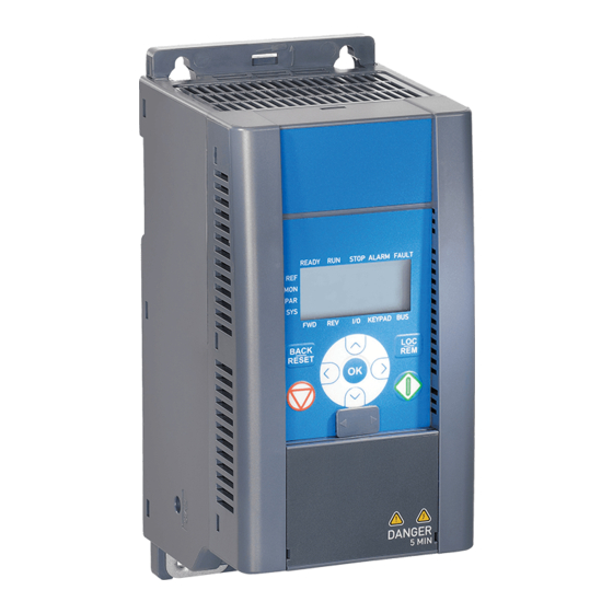
Page 30: Keypad
Stop button button Figure 7.1: Vacon 10 Control panel 7.3 Keypad The keypad section of the control panel consists of a navigation wheel and START and STOP buttons (see Figure 7.1). The navigation wheel is used for navigating on the panel display, but it also works as a reference potentiometer when KEYPAD has been selected as the control place of the drive. -
Page 31: Navigation On The Vacon 10 Control Panel
7.4 Navigation on the Vacon 10 control panel This chapter provides you with information on navigating the menus on Vacon 10 and editing the values of the parameters. 7.4.1 Main menu The menu structure of Vacon 10 control software consists of a main menu and several submenus. -
Page 32: Reference Menu
• vacon control panel 7.4.2 Reference menu READY RUN STOP ALARM FAULT I/O KEYPAD Push to enter Change Push to edit mode value confirm Figure 7.3: Reference menu display Move to the reference menu with the navigation wheel (see Figure 7.2). The refe- rence value can be changed with the navigation wheel as shown in Figure 7.3. -
Page 33: Monitoring Menu
Calculated motor speed M1.4 Motor current Measured motor current Calculated actual/nominal M1.5 Motor torque torque of the motor Calculated actual/nominal M1.6 Motor power power of the motor Table 7.1: Vacon 10 monitoring signals 24-hour support +358 (0)40 837 1150 • Email: vacon@vacon.com... - Page 34 PI feedback actual value In percent of the maximum M1.19 PI error value error value In percent of the maximum out- M1.20 PI Output put value Table 7.1: Vacon 10 monitoring signals Tel. +358 (0)201 2121 • Fax +358 (0)201 212205...
-
Page 35: Parameter Menu
The following figure shows the parameter menu view: Alternates in the display READY RUN STOP ALARM FAULT KEYPAD Browse Push to enter Change Push to P1.1 -> edit mode value confirm Figure 7.5: Parameter menu 24-hour support +358 (0)40 837 1150 • Email: vacon@vacon.com... -
Page 36: Fault History Menu
• vacon control panel 7.4.5 Fault history menu READY RUN STOP ALARM FAULT READY RUN STOP ALARM FAULT Push I/O KEYPAD BUS I/O KEYPAD Browse faults 1-9 READY RUN STOP ALARM FAULT READY RUN STOP ALARM FAULT Push I/O KEYPAD BUS... -
Page 37: General Purpose Application Parameters
Unit of parameter value; given if available Default: Factory preset value ID number of the parameter (used with fieldbus control) More information on this parameter available in chapter 9: ‘Param- eter descriptions’ click on the parameter name. 24-hour support +358 (0)40 837 1150 • Email: vacon@vacon.com... - Page 38 Activated by digital P3.4 Preset speed 0 0,00 P3.2 5,00 inputs Activated by digital P3.5 Preset speed 1 0,00 P3.2 10,00 inputs Activated by digital P3.6 Preset speed 2 0,00 P3.2 15,00 inputs Activated by digital P3.7 Preset speed 3 0,00 P3.2...
- Page 39 P10.4 Automatic restart 0 = Not used 1 = Used 0 = All parameters visi- Parameter P13.1 1 = Only quick setup conceal parameter group vis- ible Table 8.1: Quick setup parameters 24-hour support +358 (0)40 837 1150 • Email: vacon@vacon.com...
- Page 40 0 = Frequency control P1.8 mode 1 = Speed control 0 = Linear P1.9 U/f ratio selection 1 = Squared 2 = Programmable Field weakening P1.10 50,00 30,00 point Voltage at field % of Nominal voltage of P1.11 100,00 10,00 weakening point...
-
Page 41: Frequency References (Control Panel: Menu Par -> P3)
40,00 129 Activated by digital inputs P3.11 Preset speed 7 0,00 P3.2 50,00 130 Activated by digital inputs Table 8.4: Frequency references NOTE! These parameters are shown, when P13.1 = 0. 24-hour support +358 (0)40 837 1150 • Email: vacon@vacon.com... -
Page 42: Ramps And Brakes Setup (Control Panel: Menu Par -> P4)
8.5 Ramps and brakes setup (Control panel: Menu PAR -> P4) Code Parameter Unit Default Note 0 = Linear P4.1 Ramp shape 10,0 >0 = S-curve ramp time P4.2 Acceleration time 3000 P4.3 Deceleration time 3000 DC braking cur- Unit Unit P4.4... -
Page 43: Analogue Inputs (Control Panel: Menu Par -> P6)
6 = Reversed 7 = At Speed 8 = Motor Regulator Active In all API versions Relay output 2 P7.2 314 As parameter 7.1 content Table 8.8: Digital and analogue outputs 24-hour support +358 (0)40 837 1150 • Email: vacon@vacon.com... -
Page 44: Protections (Control Panel: Menu Par -> P9)
Motor ambient P9.8 temperature Motor cooling fac- P9.9 150,0 40,0 tor at zero speed Motor thermal P9.10 time constant Table 8.9: Protections NOTE! These parameters are shown, when P13.1 = 0. Tel. +358 (0)201 2121 • Fax +358 (0)201 212205... -
Page 45: Autorestart Parameters (Control Panel: Menu Par -> P10)
• parameters vacon 8.10 Autorestart parameters (Control panel: Menu PAR -> P10 ) Code Parameter Unit Default Note Delay before automatic P10.1 Wait time 0,10 10,00 0,50 restart after a fault has dis- appeared Defines the time before the frequency converter tries to P10.2... -
Page 46: Pi Control Parameters (Control Panel: Menu Par -> P12)
1 = PI for motor control 2 = PI for external use P12.2 PI controller gain 1000 100,0 PI controller I- P12.3 0,00 320,0 10,00 time Keypad PI refer- P12.4 100,0 ence 0 = Keypad PI reference, P12.4 1 = Fieldbus P12.5... -
Page 47: Easy Usage Menu (Control Panel: Menu Par -> P0)
3=2400, 4=4800, 5=9600, S2.5 Number of stop bits 0=1, 1=2 S2.6 Parity type 0= None (locked) 0= Not used, 1= 1 second, 2= S2.7 Communication time-out 2 seconds, etc. Table 8.13: System parameters 24-hour support +358 (0)40 837 1150 • Email: vacon@vacon.com... - Page 48 • vacon parameters Code Parameter Max Default Note Reset communication sta- S2.8 1= Resets par. S2.1 Total counters (MENU PAR -> S3) S3.1 MWh counter S3.2 Power on days S3.3 Power on hours User settings (MENU PAR -> S4) S4.1...
-
Page 49: Parameter Descriptions
Squared U/f ratio can be used in applications where torque demand of the load is pro- portional to the square of the speed, e.g in centrifugal fans and pumps 24-hour support +358 (0)40 837 1150 • Email: vacon@vacon.com... - Page 50 Par. 1.13 (Def. 50%) Default: Nominal frequency of the Par. 1.14 motor f[Hz] (Def. 0.0%) Par. 1.12 Par. 1.10 (Def. 10%) Figure 9.2: Programmable U/f curve Tel. +358 (0)201 2121 • Fax +358 (0)201 212205...
- Page 51 See parameters 1.9 - 1.14 and Figures 9.1 and 9.2. When the parameters 1.1 and 1.2 (nominal voltage and nominal frequency of the motor) are set, the parameters 1.10 and 1.11 are automatically given the corresponding values. If you need different values for the field weakening point and the voltage, change these parameters after setting the parameters 1.1 and 1.2.
- Page 52 WITCHING FREQUENCY Motor noise can be minimised using a high switching frequency. Increasing the switching frequency reduces the capacity of the frequency converter unit. Switching frequency for Vacon 10: 1.5…16 kHz. 1.17 B RAKE CHOPPER Note! An internal brake chopper is installed in three phase supply MI2 and MI3...
-
Page 53: Start/Stop Setup (Control Panel: Menu Par -> P2)
Local = Keypad is the control place Remote = P2.1 defines the control place TART FUNCTION The user can select two start functions for Vacon 10 with this parameter: 0 = Ramp start The frequency converter starts from 0 Hz and accelerates to the set frequency reference within the set acceleration time (P4.2). - Page 54 • vacon parameter descriptions TOP FUNCTION Two stop functions can be selected in this application: 0 = Coasting The motor coasts to a halt without control from the frequency convert- er after the Stop command. 1 = Ramp stop After the Stop command, the speed of the motor is decelerated ac- cording to the set deceleration parameters.
- Page 55 The start and end of the acceleration and deceleration ramp can be smoothed with this parameter. Setting value 0 gives a linear ramp shape which causes acceleration and deceleration to act immediately to the changes in the refer- ence signal. 24-hour support +358 (0)40 837 1150 • Email: vacon@vacon.com...
- Page 56 • vacon parameter descriptions Setting value 0.1…10 seconds for this parameter produces an S-shaped accel- eration/deceleration. The acceleration and deceleration times are determined with parameters 4.2 and 4.3. [Hz] P4.2, 4.3 P4.1 P4.1 Figure 9.3: S-shaped acceleration/deceleration C BRAKING TIME AT START DC-brake is activated when the start command is given.
- Page 57 4.7 determines the braking time. When the frequency is 10% of the nominal, the braking time is 10% of the set value of parameter 4.7.
- Page 58 • vacon parameter descriptions Par. 2.3 = 1 (Stop function = Ramp): After the Stop command, the speed of the motor is reduced according to the set deceleration parameters, if the inertia of of the motor and load allows that, to the speed defined with parameter 4.6, where the DC-braking starts.
- Page 59 1 = DI1 2 = DI2 (API FULL & LIMITED) 3 = DI3 (API FULL & LIMITED) 4 = DI4 (API FULL) 5 = DI5 (API FULL) 6 = DI6 (API FULL) 24-hour support +358 (0)40 837 1150 • Email: vacon@vacon.com...
-
Page 60: Analoque Inputs (Control Panel: Menu Par -> P6)
• vacon parameter descriptions 9.6 Analoque inputs (Control panel: Menu PAR -> P6) & SIGNAL FILTER TIME ONLY IN API FULL LIMITED SIGNAL FILTER TIME ONLY IN API FULL This parameter, given a value greater than 0, activates the function that filters out disturbances from the incoming analogue signal. - Page 61 7 = At speed reference 8 = Motor regulator One of the limit regulators (e.g. current activated limit, voltage limit) is activated Table 9.2: Output signals via RO1, RO2 and DO1 24-hour support +358 (0)40 837 1150 • Email: vacon@vacon.com...
- Page 62 9.8 Motor thermal protection (parameters 9.7 - 9.10) The motor thermal protection is to protect the motor from overheating. The Vacon drive is capable of supplying higher than nominal current to the motor. If the load re- quires this high current there is a risk that the motor will be thermally overloaded.
- Page 63 2xt6. If the drive is in stop state the time constant is internally increased to three times the set parameter value. See also Figure 9.9. 24-hour support +358 (0)40 837 1150 • Email: vacon@vacon.com...
- Page 64 Time constant T *) Q = (I/I T ) 2 x (1-e -t/T ) Time Motor temperature Changes by motor size and adjusted with parameter 9.10 Figure 9.9: Motor temperature calculation Tel. +358 (0)201 2121 • Fax +358 (0)201 212205...
- Page 65 Oth- erwise the fault is cleared after the trial time has elapsed and the next fault starts the trial time count again. See Figure 9.10. If a single fault remains during the trial time, a fault state is true.
-
Page 66: Par. 12.8
CONTROLLER GAIN This parameter defines the gain of the PI controller. If the value of the param- eter is set to 100% a change of 10% in the error value causes the controller output to change by 10%. 12.3 PI... -
Page 67: Par
PERFORM THE SAME PERFORM DRIVE SETUP, PROCEDURE FOR PAR. 1.4, PAR. 13.2, SEE NEXT PAGE MOTOR NOMINAL CURRENT Figure 9.12: Startup wizard 24-hour support +358 (0)40 837 1150 • Email: vacon@vacon.com... -
Page 68: Par
• vacon parameter descriptions READY RUN STOP A LARM FAULT READY RUN STOP ALARM FAULT READY R UN STOP ALARM FAULT PA R Startup wizard Push to enter Select between shows par 13.2 edit mode. 0 - 3, see below! number. -
Page 69: Fieldbus Parameters (Control Panel: Menu Par -> S2)
• parameter descriptions vacon 9.12 Fieldbus parameters (Control panel: Menu PAR -> S2) The built-in Modbus connection of Vacon 10 supports the following function codes: - 03 Read Holding Registers - 04 Read Input Registers - 06 Preset Single Registers 9.12.1 Modbus process data... - Page 70 Table 9.7: Control word: In Vacon applications, the three first bits of the control word are used to control the frequency converter. However, you can customise the content of the control word for your own applications because the control word is sent to the frequency converter as such.
- Page 71 Rising edge of this bit will reset active fault Drive not ready Drive ready No fault Fault active No warning Warning active AREF Ramping Speed reference reached Drive is running at zero speed 24-hour support +358 (0)40 837 1150 • Email: vacon@vacon.com...
- Page 72 45…66 Hz Line current THD > 120% Connection to mains Once per minute or less (normal case) Supply network Vacon 10 cannot be used with corner grounded networks Motor Output voltage 0 - U connection Output current Continuous rated current I at ambient temperature max.
-
Page 73: Technical Data
Immunity Complies with EN50082-1, -2, EN61800-3 Emissions 230V : Complies with EMC category C2 (Vacon level H); With an internal RFI filter 400V: Complies with EMC category C2 (Vacon level H): With an internal RFI filter Both: No EMC emission protection (Vacon level N): With-... -
Page 74: Power Ratings
• vacon technical data 10.2 Power ratings 10.2.1 Vacon 10 - Mains voltage 208 - 240 V Mains voltage 208-240 V, 50/60 Hz, 1~ series Rated loadability Motor Nominal Mechani- shaft input cur- cal size Frecuency converter power rent type weight 100% contin.