Advertisement
Quick Links
Advertisement

Subscribe to Our Youtube Channel
Related Manuals for APART REVAMP4100


Summary of Contents for APART REVAMP4100
- Page 1 REVAMP4100 Instruction manual...
- Page 3 REVAMP4100 Instruction manual REVAMP4100 manual...
-
Page 4: Safety First
DIGITAL POWER AMPLIFIER Safety first! • Caution! This professional device needs to be installed by qualified personnel only. • Please check the carton box for any kind of damage on reception of the goods. In case of a damaged carton, please contact your dealer before opening the carton. - Page 5 REVAMP4100 Instruction manual • Set level controls on amplifiers all the way down during power- up to prevent speaker damage if there are high signal levels at the inputs. • Do not connect the inputs / outputs of amplifiers or consoles...
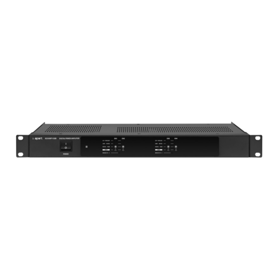
- Page 6 DIGITAL POWER AMPLIFIER Features • 1 rack unit high • High power class-D power amplifier module • Bridgeable 4 channel amplifier • Dynamic output power: 4 x 110 W @ 4 ohms • Sine wave power per channel: 4 x 100 W @ 4 ohms (500 ms) •...
- Page 7 REVAMP4100 Instruction manual Connections 17 18 20 21 22 1. Channel 4 overload led: when this led lights up, you are overloading the input. Lower the input signal immediately to prevent distortion. 2. Channel 3 overload led: when this led lights up, you are overloading the input.
- Page 8 DIGITAL POWER AMPLIFIER disconnect the speaker(s) before (de-)activating bridge mode ! In bridge mode, the input signal from channel 3 is used. 6. Channel 2 overload led: when this led lights up, you are overloading the input. Lower the input signal immediately to prevent distortion.
- Page 9 REVAMP4100 Instruction manual 14. Channel 1 speaker output on 2 pole euroblock connector. 15. Channel 4 unbalanced input and link cinch connector: connect the line level input signal for channel 4 here. Line level is 0 dBV. Input and link connector are internally connected 1 on 1.
-
Page 10: Operation
DIGITAL POWER AMPLIFIER Operation 1. Removable rack ears for 19” rack mounting. 2. Power switch: after switching on the power, the power led will light up after approx 1 second. 3. Power led 4. Channel 1 status led bar and mute switch: when the mute switch is pressed, the orange “LIMIT –... - Page 11 REVAMP4100 Instruction manual 6. Channel 2 status led bar and mute switch: when the mute switch is pressed, the orange “LIMIT – MUTED” led will light up. This led will also light up when the internal limiter is activated to avoid the amplifier from being overloaded by high input signals.
-
Page 12: Important Notice
DIGITAL POWER AMPLIFIER Important notice This amplifier relies on convectional cooling only. In normal situations, overheating will not occur due to the class D amplifier topology. Since there are no cooling fans in the amplifier, make sure the convectional cooling system can work properly. The unit can be built in a 19 inch rack system, but it is forbidden to block the ventilation holes provided. -
Page 13: Technical Specifications
REVAMP4100 Instruction manual Technical specifications 19” (483 mm wide) rack mounting Height rack units in U (1U = 44 mm) Depth (built-in) 230 mm Depth (incl. front) 239 mm Power supply 100 - 254 VAC / 50 - 60 Hz... - Page 14 DIGITAL POWER AMPLIFIER Channel separation > 65 dB @ 1kHz Damping factor > 50 @ 1 kHz all channels APC system clip limiter Cooling system convectional Power amp topology class-D Power supply SMPS Operating temperature range 0 to 40°C Dimensions (w x h x d) 483 x 44 x 239 (including rack ears and front).
- Page 16 Audioprof nv Industriepark Brechtsebaan 8 bus 1 2900 Schoten - Belgium Company names, product names and trademarks are property of their respective owners. Apart-Audio specifications are subject to change without notice.
Need help?
Do you have a question about the REVAMP4100 and is the answer not in the manual?
Questions and answers