Laars NEOTHERM NTH Series Installation And Operation Instructions Manual
Modulating boiler sizes 080–210 mbtu/h
Hide thumbs
Also See for NEOTHERM NTH Series:
- Startup manual (16 pages) ,
- Manual (20 pages) ,
- Installation and operation instructions manual (104 pages)
Table of Contents
Advertisement
Quick Links
Installation and Operation Instructions
FOR YOUR SAFETY: This product must be installed and serviced by a professional service technician,
qualified in hot water boiler and heater installation and maintenance. Improper installation and/or operation
could create carbon monoxide gas in flue gases which could cause serious injury, property damage, or
death. Improper installation and/or operation will void the warranty.
If the information in this manual is not followed
exactly, a fire or explosion may result causing
property damage, personal injury or loss of life.
Do not store or use gasoline or other flammable
vapors and liquids in the vicinity of this or any
other appliance.
WHAT TO DO IF YOU SMELL GAS
• Do not try to light any appliance.
• Do not touch any electrical switch; do not use
any phone in your building.
• Immediately call your gas supplier from a
nearby phone. Follow the gas supplier's
instructions.
• If you cannot reach your gas supplier, call the
fire department.
Installation and service must be performed by
a qualified installer, service agency, or gas supplier.
WARNING
Installation and Operation
Instructions for
Modulating Boiler
Model NTH
Sizes 080–210 MBTU/h
AVERTISSEMENT
Assurez-vous de bien suivres les instructions
données dans cette notice pour réduire au
minimum le risque d'incendie ou d'explosion ou
pour éviter tout dommage matériel, toute blessure
Ne pas entreposer ni utiliser d'essence ni d'autres
vapeurs ou liquides inflammables dans le voisinage
de cet appareil ou de tout autre appareil.
QUE FAIRE SI VOUS SENTEZ UNE ODEUR DE GAZ:
• Ne pas tenter d'allumer d'appareils.
• Ne touchez à aucun interrupteur. Ne pas vous servir des
téléphones dansle bâtiment où vous êtes.
• Appelez immédiatement votre fournisseur de
gaz depuis un voisin. Suivez les instructions du
fournisseur.
• Si vous ne pouvez rejoindre le fournisseur de gaz,
appelez le sservice des incendies.
L'installation et l'entretien doivent être assurés par un
installateur ou un service d'entretien qualifié ou par le
fournisseur de gaz.
Document 1252G
®
ou la mort.
Advertisement
Table of Contents

Related Manuals for Laars NEOTHERM NTH Series


Summary of Contents for Laars NEOTHERM NTH Series
- Page 1 Installation and Operation Instructions Document 1252G Installation and Operation Instructions for ® Modulating Boiler Model NTH Sizes 080–210 MBTU/h FOR YOUR SAFETY: This product must be installed and serviced by a professional service technician, qualified in hot water boiler and heater installation and maintenance. Improper installation and/or operation could create carbon monoxide gas in flue gases which could cause serious injury, property damage, or death.
-
Page 2: Table Of Contents
LAARS Heating Systems Table of Contents SECTION 1 SECTION 6 GENERAL INFORMATION WATER CONNECTIONS Introduction ............5 System Piping - Hot Supply Connections ............ 22 Warranty ............5 Model Identification ........... 5 Cold Water Make-Up ........22 Condensate Drain ........... 23 Safety Notes ............. - Page 3 Residential Boilers HERM ® SECTION 9 FIRST START-UP AND ADJUSTMENT INSTRUCTIONS Filling the Boiler System ......... 54 First Operation ..........55 Restarting the Unit .......... 55 Shutting Down the Unit ........55 SECTION 10 MAINTENANCE 10.A System Maintenance ........56 10.B Maintenance and Component Description ............
- Page 4 LAARS Heating Systems...
-
Page 5: General Information
INFORMATION 1.A Introduction This manual provides information necessary for the installation, operation, and maintenance of the LAARS NOTE: Throughout the content of this manual, Heating Systems NeoTherm. Read it carefully before the NeoTherm will be referred to as a ‘unit’. -
Page 6: D Safety Notes
LAARS Heating Systems Page 6 1.D Safety Notes Safety Notes are used thoughout this manual to bring attention to the presence of hazards with various risk levels and to off er important information concering the life of this product. There are 3 basic types. - Page 7 Residential Boilers HERM ® Page 7 WARNING NOTE: All installations must be made in accordance with 1) American National Standard Z223.1/NFPA54-Latest Electrical Shock Hazard Edition “National Fuel Gas Code” or Electrical shock can cause severe injury, death or 2) CSA B149.1 “Natural Gas and Propane Installation property damage.
-
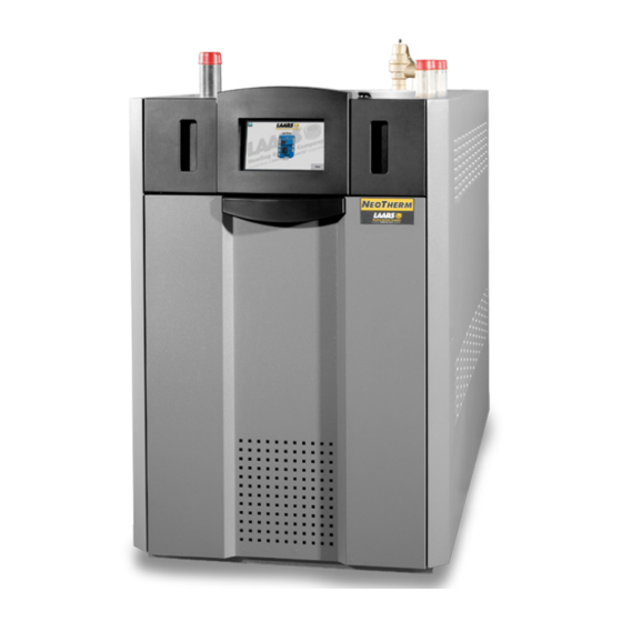
Page 8: E Model Overview
LAARS Heating Systems Page 8 Model Overview EXHAUST VENT PRESSURE RELIEF VALVE CONNECTION WATER INLET GAS CONNECTION WATER OUTLET AIR INLET CONNECTION USER CONTROL INTERFACE ON / OFF SWITCH HEAT EXCHANGER DRAIN VALVE GAS VALVE CONDENSATE TRAP VENTURI AIR TRANSITION... -
Page 9: F Dimensions
Residential Boilers HERM ® Page 9 Dimensions Dimensions are nominal and are shown in inches Optional pump is shown only in the front view AIR INLET VENT Size 13½ 34 9½ 24 7½ 19 10¾ 28 11¾ 30 13¾ 35 3½... -
Page 10: G The Installation Kit
LAARS Heating Systems Page 10 1.G The Installation Kit This residential unit is shipped in a single crate with a boxed installation kit that contains these components. (See Figure 1. Temperature / pressure gauge kit 2. Air intake terminal 3. Exhaust vent terminal (US only) 4. -
Page 11: Locating The Unit
Residential Boilers HERM ® Page 11 SECTION 2 LOCATING THE UNIT 2.A General Information This unit is designed for indoor installations only and SUGGESTED SERVICE ACCESS CLEARANCE should be located to provide clearances on all sides for UNIT SURFACE INCHES maintenance and inspection. -
Page 12: A General Venting
LAARS Heating Systems Page 12 SECTION 3 VENTING AND COMBUSTION AIR 3.A General Venting This unit requires a special venting system. Refer to Do not mix venting suppliers and models in venting venting supplier’s instructions for complete parts list and systems. - Page 13 Residential Boilers HERM ® Page 13 Combustion Air From Room Other methods of introducing combustion and ventilation air are acceptable, providing they conform to the requirements In the United States, the most common requirements in the applicable codes listed above. specify that the space shall communicate with the outdoors in accordance with method 1 or 2, which follow.
-
Page 14: C Venting
LAARS Heating Systems Page 14 3.C Venting must be produced by the same manufacturer, and have a WARNING ULC-S636 rating. All installations should be done following the vent supplier’s Failure to use polypropylene CPVC or stainless steel venting for the first 30” of vent material or for any part of recommended installation techniques. -
Page 15: D Common Venting
Residential Boilers HERM ® Page 15 Class II venting systems are further classified into four temperature ratings as follows: Up to and including 65°C Up to and including 90°C Up to and including 110°C, and Up to and including 135°C NOTE: IMPORTANT! It is the responsibility of the installer to ensure that a flue gas sampling port is In Canada, refer to CAN/CSA B149.1... -
Page 16: E Locating Vent & Combustion Air Terminals
LAARS Heating Systems Page 16 3.E Locating Vent and Combustion Air Do not locate the air inlet terminal near a source Terminals (continued) of corrosive chemical fumes (e.g., cleaning fluid, Figure 7 shows the requirements for mechanical vent chlorine compounds, etc.) terminal clearances for the U.S. - Page 17 Residential Boilers HERM ® Page 17 U.S. Installations (see note 1) Canadian Installations (see note 2) A= Clearance above grade, veranda, porch, 12 inches (30 cm) 12 inches (30 cm) deck, or balcony See note 6 See note 6 B= Clearance to window or door that may be Direct vent only: 12 inches (30cm);...
- Page 18 LAARS Heating Systems Page 18 3.E Locating Vent and Combustion Air however, that during said thirty (30) day period, a Terminals (continued) battery operated carbon monoxide detector with an alarm be installed. Installations in the Commonwealth of Approved Carbon Monoxide Detectors...
-
Page 19: F Common Vent Test
Residential Boilers HERM ® Page 19 Common Vent Test SECTION 4 GAS SUPPLY AND PIPING NOTE: This section does not describe a method for common venting units. It describes what must be done when a unit is removed from a common vent system. All Installations must conform to the National Fuel Gas Code These class IV units require special vent systems and ANSI Z223.1/NFPA54, and/or local codes. -
Page 20: A Boiler Flow And Head Requirements
LAARS Heating Systems Page 20 EQUIVALENT LENGTHS OF STRAIGHT PIPE FOR TYPICAL SCH 40 FITTINGS Unit NATURAL GAS NOMINAL PIPE SIZE REQUIRED 1/2” 3/4” 1” 1-1/4” 1-1/2” 2” FITTING TO SIZE PIPING: CU FT Measure linear distance from meter outlet to SIZE / HR. - Page 21 Residential Boilers HERM ® Page 21 NOTE: This unit and all other gas appliances sharing SCHED 40 METAL PIPE CAPACITY FOR 1.50 SPECIFIC GRAVITY the gas supply line must be firing at maximum UNDILUTED PROPANE NOMINAL PIPE SIZE 11” W.C. INLET AND 0.5” W.C. PRESSURE DROP capacity to properly measure the inlet supply 1/2”...
-
Page 22: Water Connections
LAARS Heating Systems Page 22 SECTION 6 WATER CONNECTIONS 6.A Boiler System Piping - Hot Supply Connections When the pump is supplied by the units manufacturer, the NOTE: This unit must be installed in a closed pressure boiler must be located within 15 feet (4.6m) of the supply system with a minimum of 12 psi (82.7kPa) static... -
Page 23: C Condensate Drain
Residential Boilers HERM ® Page 23 6.C Condensate Drain A condensate drain trap is built into the unit. NOTE: Manufacturer supplied pumps are not all capable Connect a 3/4” PVC pipe between the drain connection of maintaining the reduced temperature rise required and a floor drain (or a condensate pump if a floor drain is with glycol concentrations greater than 35%. - Page 24 LAARS Heating Systems Page 24 Figure 9. Hydronic Piping — Single Boiler, Zoning with Circulators...
- Page 25 Residential Boilers HERM ® Page 25 Figure 10. Hydronic Piping — Single Boiler, Low Temp Radiant Space Heating Using Low Loss Header and Zone Valves...
- Page 26 LAARS Heating Systems Page 26 Figure 11. Hydronic Piping — Multiple Boilers, Zoning with Circulators...
- Page 27 Residential Boilers HERM ® Page 27 Figure 12. Hydronic Piping — Multiple Boilers with Indirect DHW Tank Piped from System Loop...
- Page 28 LAARS Heating Systems Page 28 Figure 13. Hydronic Piping — Multiple Boilers, Reverse Return, Multi-Temp Zones, Zoning with Circulators...
- Page 29 Residential Boilers HERM ® Page 29 Figure 14. Hydronic Piping — Heating Zones with Indirect DHW Tank Piped with Zone Pumps The indirect DHW tank is piped directly off of the boiler.
- Page 30 LAARS Heating Systems Page 30 Figure 15. Hydronic Piping, Multiple Boilers with Indirect DHW Off of One Boiler The indirect DHW tank is piped directly off of the boiler.
-
Page 31: A Installation Warnings
This unit must be electrically grounded in accordance blocks. with the requirements of the authority having Note: all units with Laars supplied boiler pumps may be DOCUMENT 1252F (H2355200F) ‐ PAGE 26 jurisdiction or, in the absence of such requirements, powered using the supplied voltage. -
Page 32: C Pump Connections And Operation
LAARS Heating Systems Page 32 7.C Pump Connections and Operation Optional Field Connections The controller in the unit energizes the boiler pump contacts Terminal block 8 (TB8) in the control panel is used for the when it receives a call for heat. Once the call for heat is ‘Safety Chain’... - Page 33 Residential Boilers HERM ® Page 33 Figure 16. Control Panel Layout...
-
Page 34: F Lead Lag Connections
LAARS Heating Systems Page 34 Lead Lag Connections Lead Boiler These boilers can be connected in a lead / lag series up to a total of 8 residential Units. One as the Lead control and 7 more as the following controllers. - Page 35 Residential Boilers HERM ® Page 35 These boilers can be controlled and monitored using a BAS Following Boiler (Building Automation Systems) control, but only if one of the EMEA User Interfaces is replaced with the available color touchscreen. Call your Manufacturers Representative for the touchscreen kit Optional Touchscreen User Interface Kit (KM50D7130) and the BAS Control (H2354400, Doc# 4236).
-
Page 36: G System Wiring Diagram
LAARS Heating Systems Page 36 7.G System Wiring Diagram OPTIONAL SWITCH USED ON SOME MODELS. IF SWITCH TO J4-10 IS NOT INSTALLED IN THIS LOCATION. THE TERMINAL JUMPER VALVE SHOULD BE IN PLACE OR/WH COMMON PRESSURE SWITCH "HOT" TO TB1 PIN2... - Page 37 Residential Boilers HERM ® Page 37 LTGN OR/GN DISPLAY DISPLAY (Honeywell) (Honeywell) OPTIONAL SWITCH USED ON SOME MODELS. IF SWITCH IS NOT INSTALLED IN THIS LOCATION, THE TERMINAL JUMPER SHOULD BE IN PLACE PRESSURE SWITCH BOILER OR/GN BOILER PUMP PUMP GY/GN INTERRUPT BOILER...
-
Page 38: H Ladder Diagram
LAARS Heating Systems Page 38 7.H Ladder Diagram Figure 19. - Ladder Diagram... -
Page 39: The User Interface
Residential Boilers HERM ® Page 39 SECTION 8 THE USER INTERFACE 8.B Navigating the User Interface 8.A About the User Interface Navigating into the Display Area is as easy as it looks. The The User Interface has two main parts: Info/Install button will be the primary button that you will use •... -
Page 40: The Home Display
LAARS Heating Systems Page 40 8.D Customizing your Home Display The ‘User Interface’ was updated for the To customize the upper section of your Home Display 2013 model year to the EMEA display shown in • Press “I” Info/Install button Figure 20. - Page 41 Residential Boilers HERM ® Page 41 Quick Start This menu gives you an easy way to check or change the most common set- tings on the unit: • CH setpoint • DHW setpoint • Outdoor reset • Low water temperature •...
- Page 42 LAARS Heating Systems Page 42 (function turned off) and 15 hours. made when the system is installed, and some diagnostic and troubleshooting functions. The In this example we will change the time delay to 5 minutes. l n t installer level password is “...
-
Page 43: F Quick Start Menu
Residential Boilers HERM ® Page 43 Quick Start Changing a Value Using a “Slider” There is another type of control screen that you may see. This type of screen uses a “slider” to set the value. This system is used on the LCD Contrast screen (available under Display Setup.) See “Figure 27. -
Page 44: Configuration And Setup
LAARS Heating Systems Page 44 Configuration and Setup Outdoor Reset Functions - 8.G 24 VAC Transform with Integral Circuit The next four lines in the display are used to set up the Breaker Outdoor Reset functions: 24 VAC is supplied by a transformer mounted underneath •... -
Page 45: J Outdoor Air Temperature Sensor
Residential Boilers HERM ® Page 45 Figure 30. - Control Panel Layout Outdoor Air Temperature Sensor The sloping line in Figure 31 shows the setpoint which The outdoor air temperature sensor is used with the is actually used by the system. Without Outdoor Reset, Outdoor Reset and Warm Weather Shutdown functions. -
Page 46: (Including Passwords)
LAARS Heating Systems Page 46 Here are instructions for setting up the Outdoor Reset How to get there: From the “Home” screen, press “I” to function. Notice that these instructions will be different, go to “Info/ Install.” Choose “Advanced Setup,” then go to “Lead/ Lag Configuration.”... -
Page 47: M Domestic Hot Water
Residential Boilers HERM ® Page 47 different, depending on whether your system has a single wiring and control setup for several different types of DHW boiler or more than one boiler (using Lead Lag operation). supplies. Wiring Connections - DHW Temperature Setting - Connect the outdoor temperature sensor.: Regardless of the type of DHW setup, the setpoint adjustment is made the same way. - Page 48 LAARS Heating Systems Page 48 (For a complete explanation of the Lead Lag system, see Boiler Pump Interrupt Function - Section 8.14.) The boiler pump interrupt feature is used in some When using the Lead Lag boiler system to provide indirect...
-
Page 49: About Lead Lag Operation
Residential Boilers HERM ® Page 49 3. Set the DHW priority time. If the DHW function has the priority, the priority will continue during the priority time. If your system has just one boiler – How to get there: From the “Home” screen, press “I” to go to “Info/ Install.”... - Page 50 LAARS Heating Systems Page 50 About Lead Lag Operation (continued) Boiler 1 Boiler 2 Boiler 3 Boiler 4 Display Controller Burner Figure 33. “Lead Lag” Operation in a System with Four Boilers. Note - the Displays on Boilers 2 thru 4 will display information pertaining only to that specific boiler.
- Page 51 Residential Boilers HERM ® Page 51 Low demand - Low demand - The first boiler in The first boiler in sequence fires at sequence fires at less than 65% less than 65% First Third Fourth First Third boiler boiler boiler boiler boiler Demand increases -...
-
Page 52: O Adjusting Co 2
LAARS Heating Systems Page 52 Adjusting CO About Lead Lag Operation (continued) in the flue products at high Measure the CO fire. The Unit can be forced to high fire to allow Control Settings for Lead Lag System - Part 2 for easier setup. - Page 53 Residential Boilers HERM ® Page 53 The Gas Valve in the 80 thru 210 is at the front of the unit and can be reached after the front panel is pulled forward and then off. Always be patient with your combustion analyzer when making adjustments to the valve at both Hi-Fire and Low- Fire.
-
Page 54: First Start-Up And Adjustment Instructions
LAARS Heating Systems Page 54 SECTION 9 FIRST START-UP units and high points in the system piping, as described in Step 4. AND ADJUSTMENT Close the make-up water valve and check the strainer INSTRUCTIONS in the pressure reducing valve for sediment or debris from the make-up water line. -
Page 55: B First Operation
Residential Boilers HERM ® Page 55 9.B First Operation 9.C Restarting the Unit If the unit has been drained, see Section 9.1 in this CAUTION manual for instructions on filling and purging the unit The initial setup must be checked before the unit is properly. -
Page 56: Maintenance
LAARS Heating Systems Page 56 SECTION 10 MAINTENANCE The gas and electric controls in the unit are engineered for long life and dependable operation, but the safety of WARNING equipment depends on their proper functioning. Only a qualified service technician should inspect the basic items... - Page 57 Residential Boilers HERM ® Page 57 Unit Control Flame Sensor The flame sensor is a single rod system. To replace the This unit has an integrated control that incorporates flame sensor electrode, shut off the 120 Volt power supply manual reset high limit control, operating temperature to the boiler.
-
Page 58: C Gas Conversion
LAARS Heating Systems Page 58 Heat Exchanger Coils WARNING Black carbon soot buildup on the heat exchanger is caused Failure to rinse the debris from the heat exchanger and by one or more of the following; incomplete combustion, temporary drain line may lead to clogged condensate combustion air problems, venting problems, or heater short lines, traps and neutralizers. - Page 59 Residential Boilers HERM ® Page 59 size (mbtu) Kit number CA006201 CA006202 CA006203 CA006204 Table 20. - Propane Gas Conversion Kits size (mbtu) Kit number CA006206 CA006206 CA006206 CA006206 Table 21. - Natural Gas Conversion Kits...
-
Page 60: Operating Details And Troubleshooting
LAARS Heating Systems Page 60 SECTION 11 OPERATING period an intermittent spark can be seen. DETAILS AND Next there is a trial for ignition period of four seconds. TROUBLESHOOTING The direct spark ignition switches to constant spark for three seconds. During this time the gas valve is open. -
Page 61: F Temperature Sensors
Residential Boilers HERM ® Page 61 11.G Diagnostics This can be a symptom of improper control strategy or Use the Diagnostics to check the status of the sensors and setpoints, or a load distribution problem. The controller in the digital inputs and outputs. The system also records a the Unit includes an anti-short cycle (ASC) function. -
Page 62: Replacement Parts
LAARS Heating Systems Page 62 SECTION 12 REPLACEMENT PARTS Use only genuine Manufacturer replacement parts. 12.A General Information To order or purchase parts for these high efficiency residential units, contact your nearest manufacturers dealer or distributor. See the back cover for the manufacturers website and information. - Page 63 Residential Boilers Page 63 HERM ® SIZE SIZE SIZE SIZE ITEM DESCRIPTION PVC Reducer — — RP2053000 RP2053000 30a CPVC Reducer RD2010501 RD2010501 RP2065600 RP2065600 or Coupling 30b 2” Dia. Pipe, CPVC RD2010212 RD2010212 RD2010213 RD2010213 Hose Barbed Adapter RP2067100 RP2067100 RP2056100 RP2056100...
- Page 64 LAARS Heating Systems Page 64 SIZE SIZE SIZE SIZE ITEM DESCRIPTION Air/Gas Channel RS2108400 RS2108600 RS2108600 RS2108700 (80-600) Air Adapter (750-850) 75A Screw, Air/Gas RS2109400 RS2109400 RS2109400 RS2109400 Channel Drain R10-143 R10-143 R10-143 R10-143 Sight Glass R50D2020 R50D2020 R50D2020 R50D2020 Electrical Components –...
- Page 65 Residential Boilers HERM ® Page 65 Figure 41. - Jacket Components Optional Touchscreen User Interface Kit (KM50D7130) Call your local Manufacturers Rep.
- Page 66 LAARS Heating Systems Page 66 Figure 42. - Gas Train Components, Sizes 80-210 Figure 43. - Internal Components, Sizes 80–210...
- Page 67 Residential Boilers HERM ® Page 67 Figure 44. - Heat Exchanger Components...
- Page 68 LAARS Heating Systems Page 68 Figure 45. - Electrical Components...
-
Page 69: Appendix A - Software Control Functions
Residential Boilers HERM ® Page 69 APPENDIX A SOFTWARE CONTROL FUNCTIONS This table includes a listing of all of the control functions that can be used by the operator or installer. Functions that require a password are indicated in the second column. Name Function How to get there... - Page 70 LAARS Heating Systems Page 70 Name Function How to get there Demand switch (CH) Set to “STAT terminal.” Info/ Advanced Setup/ CH Configuration DHW pump control The boiler pump can be turned on manually, or it Info/ Test/ Manual Pump Operation can be set to operate automatically.
- Page 71 Residential Boilers HERM ® Page 71 Name Function How to get there Max. outdoor temp. (CH) - Used with Outdoor Reset – Quick Start This is the maximum outdoor temperature at which Info/ Advanced Setup/ CH Configuration/ Outdoor Reset Config. the Outdoor Reset feature will be active.
- Page 72 LAARS Heating Systems Page 72 Name Function How to get there Off hysteresis (DHW) When producing Domestic Hot Water – Info/ Advanced Setup/ DHW Configuration The control system will not shut off the boiler until the temperature at the System sensor rises to the DHW setpoint plus a hysteresis value (normally about 10°F).
- Page 73 Residential Boilers HERM ® Page 73 Name Function How to get there Pump exercise interval The system can be set to exercise the pumps at Info/ Advanced Setup/ System Config./ Pump Config. set intervals. Enter a non-zero value to turn on the function.
-
Page 74: Appendix Berror Messages
LAARS Heating Systems Page 74 APPENDIX B ERROR MESSAGES This table includes a listing of the faults that might be generated by the controller, and displayed on the Operator Interface. Some of these can be corrected by an installer changing a parameter, while other conditions are more complicated, and will require a service technician. - Page 75 Residential Boilers HERM ® Page 75 Internal fault: Safety relay test failed due to safety relay not OFF Internal fault Internal fault: 1. Reset module Safety relay test failed due to feedback 2. If fault repeats, replace module. not ON Internal fault: Safety RAM write Internal fault:...
- Page 76 LAARS Heating Systems Page 76 AC input phases reversed 1. Check the module and display connections. 2. Check the module power supply and make sure that both frequency and voltage meet the specifications. 3. On 24 VAC applications, assure that J4 terminal 10 and J8 terminal 2 are connected together.
- Page 77 Residential Boilers HERM ® Page 77 DHW (Domestic Hot Water) high limit H or L 1. Check wiring and correct any possible errors. 2. Replace the DHW high limit. 3. If previous steps are correct and fault persists, replace the module.
- Page 78 LAARS Heating Systems Page 78 1. Check that flame is not present in the combustion chamber. Flame detected out of sequence H or L Correct any errors. 2. Make sure that the flame detector is wired to the correct terminal.
- Page 79 Residential Boilers HERM ® Page 79 Combustion pressure and flame On 1. Check that flame is not present in the combustion chamber. H or L Correct any errors. 2. Make sure that the flame detector is wired to the correct terminal. 3.
- Page 80 LAARS Heating Systems Page 80 Invalid Blower/ HSI output setting Invalid Delta T limit enable setting Invalid Delta T limit response setting Invalid DHW (Domestic Hot Water) high limit enable setting Invalid DHW (Domestic Hot Water) high limit response setting 1.
- Page 81 Residential Boilers HERM ® Page 81 Invalid Outlet high limit response setting Invalid PII (Pre-Ignition Interlock) enable setting Invalid Postpurge time setting Invalid Power up with lockout setting 1. Recheck selected parameters, reverify and reset module. Invalid Preignition time setting 2.
- Page 82 LAARS Heating Systems Notes:...
- Page 83 Residential Boilers HERM ® Notes:...
- Page 84 800.900.9276 • Fax 800.559.1583 Headquarters: Industrial Way, Rochester, NH, USA 03867 • 603.335.6300 • Fax 603.335.3355 9 Brigden Gate, Halton Hills, Ontario, Canada L7G 0A3 • 905.203.0600 • Fax 905.636.0666 www.Laars.com Litho in U.S.A. © Laars Heating Systems 20-04 Document 1252G...
Need help?
Do you have a question about the NEOTHERM NTH Series and is the answer not in the manual?
Questions and answers