Laars NTV1000 Installation And Operation Instructions Manual
Neotherm
Hide thumbs
Also See for NTV1000:
- Installation and operation instructions manual (140 pages) ,
- User manual (12 pages) ,
- User manual (12 pages)
Table of Contents
Advertisement
Quick Links
See also:
User Manual
Installation and Operation Instructions
FOR YOUR SAFETY: This product must be installed and serviced by a professional service technician,
qualified in hot water boiler and heater installation and maintenance. Improper installation and/or operation
could create carbon monoxide gas in flue gases which could cause serious injury, property damage, or
death. Improper installation and/or operation will void the warranty.
If the information in this manual is not
followed exactly, a fire or explosion may
result causing property damage, personal
injury or loss of life.
Do not store or use gasoline or other
flammable vapors and liquids in the vicinity
of this or any other appliance.
WHAT TO DO IF YOU SMELL GAS
• Do not try to light any appliance.
• Do not touch any electrical switch; do not
use any phone in your building.
• Immediately call your gas supplier from a
nearby phone. Follow the gas supplier's
instructions.
• If you cannot reach your gas supplier, call
the fire department.
Installation and service must be performed
by a qualified installer, service agency, or gas
supplier.
WARNING
Installation and Operation
Instructions for
NeoTherm
Modulating Boiler
Model NTH1000
1,000 MBTU/h
Water Heater
Model NTV1000
1,000 MBTU/h
AVERTISSEMENT
Assurez-vous de bien suivres les instructions
données dans cette notice pour réduire au
minimum le risque d'incendie ou d'explosion
ou pour éviter tout dommage matériel, toute
blessure ou la mort.
Ne pas entreposer ni utiliser d'essence ni
d'autres vapeurs ou liquides inflammables dans
le voisinage de cet appareil ou de tout autre
appareil.
QUE FAIRE SI VOUS SENTEZ UNE ODEUR DE GAZ:
• Ne pas tenter d'allumer d'appareils.
• Ne touchez à aucun interrupteur. Ne pas vous
servir des téléphones dansle bâtiment où vous
vous trouvez.
• Appelez immédiatement votre fournisseur de
gaz depuis un voisin. Suivez les instructions
du fournisseur.
• Si vous ne pouvez rejoindre le fournisseur de
gaz, appelez le sservice des incendies.
L'installation et l'entretien doivent être assurés par
un installateur ou un service d'entretien qualifié ou
par le fournisseur de gaz.
Document 1247
®
Advertisement
Table of Contents
Troubleshooting

Related Manuals for Laars NTV1000


Summary of Contents for Laars NTV1000
- Page 1 Modulating Boiler Model NTH1000 1,000 MBTU/h Water Heater Model NTV1000 1,000 MBTU/h FOR YOUR SAFETY: This product must be installed and serviced by a professional service technician, qualified in hot water boiler and heater installation and maintenance. Improper installation and/or operation could create carbon monoxide gas in flue gases which could cause serious injury, property damage, or death.
-
Page 3: Table Of Contents
LAARS Heating Systems Table of Contents Section 1 - General Information ........1 Section 6 – Water Connections ........18 Introduction ............1 About the NeoTherm Control System ....1 Section 6A - NTH Units ........... 18 Safety Notes ............. 3 6A.1 NTH System Piping: Hot Supply Connections ............ - Page 4 LAARS Heating Systems Section 9 – Setup and Configuration ....... 44 Section 10 - Operating Instructions ......... 92 Review of Lead/Lag Control System .....44 10.1 Filling the Boiler System ........92 9.1.1 About Lead/Lag Operation ......44 10.2 Initial Operation ..........93 9.1.2 Lead/Lag Modulation Cycle ......45 10.2.1 Initial Burner Operation .........
-
Page 5: Section 1 - General Information
We just want to give you some help with LAARS Heating Systems warranty will be voided. the first part of the process, when you are “getting The installation must conform to the requirements used to” the control system. - Page 6 LAARS Heating Systems Page 2 Boiler 1 Boiler 2 Boiler 3 Boiler 4 Operator interface Addr Addr Addr Addr Addr Addr Addr Addr Lead Lag Slave 3 Slave 5 Slave 7 Master and Slave 4 Slave 1 Slave 6 Slave 8 Slave 2 fig.
-
Page 7: Safety Notes
NeoTherm Boilers and Water Heaters Page 3 Safety notes WarnInG WarnInG Fire or Explosion Hazard Electrical Shock Hazard Improper configuration can cause fuel buildup and Electrical shock can cause severe injury, death or property damage. Disconnect the power supply explosion. Improper user operation may result in property loss, severe physical injury, or death. before beginning installation or changing the wiring to prevent electrical shock or damage to the Any changes to safety-related configuration... -
Page 8: Warranty
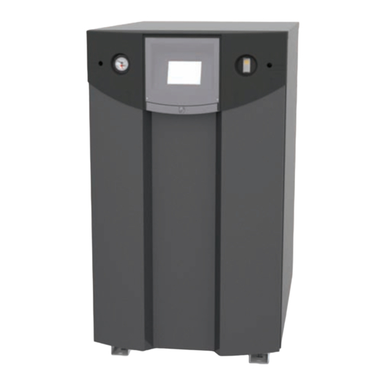
Leveling feet fig. 4 - location of Components Warranty LAARS Heating Systems’ NeoTherm appliances are Some accessory items may be shipped in separate covered by a limited warranty. The owner should packages. Verify receipt of all packages listed on complete the warranty registration at: the packing slip. -
Page 9: Dimensions
NeoTherm Boilers and Water Heaters Page 5 fig. 5 - Dimensions Dimensions DanGer The dimensions are shown in Fig. 5. • Water temperature over 125°F (52°C) can cause severe burns instantly or death from scalds. • Children, disabled and elderly are at highest risk of Unpacking being scalded. -
Page 10: Section 2 - Locating The Unit
LAARS Heating Systems Page 6 Section 2 loCatInG tHe UnIt locating the Unit The NeoTherm unit may be installed indoors or APPLIANCE SUGGESTED SERVICE ACCESS CLEARANCE outdoors. The unit may only be installed outdoors SURFACE InCHeS in a location which will never experience freezing Front 60.9... -
Page 11: Section 3 - Venting And Combustion Air
NeoTherm Boilers and Water Heaters Page 7 Section 3 VentInG anD ComBUStIon aIr Combustion air NeoTherm boilers and water heaters must have shall be of the same cross-sectional area as the free provisions for combustion and ventilation air in area of the openings to which they connect. accordance with the applicable requirements for Method 1: Two permanent openings, one Combustion Air Supply and Ventilation in the... -
Page 12: Ducted Combustion Air
The combustion air can be taken through the wall, or through the roof. When taken from the wall, it must be taken from out-of-doors by means of the LAARS horizontal wall terminal, shown in Table 3a. See Table 2 to select the appropriate diameter air pipe. -
Page 13: Venting
NeoTherm Boilers and Water Heaters Page 9 Venting vent systems, please, refer to the vent supplier’s installation instructions for proper installation WarnInG techniques. Selection of improper vent materials for installations that are installed in closets, or will be operated in high ambient temperature levels, may lead to WarnInG property damage, personal injury, or death. -
Page 14: Venting Requirements Unique To Canada
3.3.1 Side Wall Vent terminal NeoTherm unit. A flue gas sampling port available The appropriate Laars side wall vent terminal must as a component of the ULC S636 certified vent be used. The terminal must be located in accordance system is preferred. However, if one is not available with ANSI Z223.1/NFPA 54 and applicable... - Page 15 NeoTherm Boilers and Water Heaters Page 11 U.S. Installations (see note 1) Canadian Installations (see note 2) a= Clearance above grade, veranda, porch, 12 inches (30 cm) 12 inches (30 cm) deck, or balcony See note 6 See note 6 B= Clearance to window or door that may be Direct vent only: 12 inches (30 cm);...
-
Page 16: Side Wall Combustion Air Terminal
Vent terminals for condensing appliances or 3.3.2 Side Wall Combustion air terminal appliances with condensing vents are not The LAARS side wall combustion air terminal permitted to terminate above a public walkway, must be used when the heater takes air from a side or over an area where condensate or vapor wall. (See Table 3.) Contact Laars for AL29-4C... -
Page 17: Vertical Vent Terminal
NeoTherm Boilers and Water Heaters Page 13 Locate the combustion air terminal so that it up is installed on the floor level where the gas cannot be blocked by snow. The National Fuel appliance is to be installed. In addition, the in- Gas Code requires that it be at least 12 inches stalling plumber or gasfitter shall observe that a (30 cm) above grade, but the installer may battery operated or hard-wired carbon monoxide determine it should be higher, depending upon detector with an alarm is installed on each addi-... -
Page 18: Outdoor Installation
LAARS Heating Systems Page 14 When an existing boiler is removed from a common outdoor Installation venting system, the common venting system is likely The NeoTherm unit may only be installed in to be too large for proper venting of the appliances applications where the outdoor temperature doesn’t... -
Page 19: Section 4 - Gas Supply And Piping
NeoTherm Boilers and Water Heaters Page 15 Section 4 GaS SUPPly anD PIPInG Gas Supply and Piping The appliance and its individual shutoff valve Gas piping should be supported by suitable hangers must be disconnected from the gas supply or floor stands, not the appliance. piping during any pressure testing of that Installers should refer to local building and safety system at test pressures in excess of 1/2 PSIG codes or, in the absence of such requirements, follow (3.45 kPa). - Page 20 LAARS Heating Systems Page 16 neotHerm SCH 40 metal PIPe CaPaCIty for 0.60 SPeCIfIC GraVIty to SIze PIPInG: natUral GaS natUral GaS Measure linear distance from meter outlet to last boiler. Add total input of all boilers and reQUIreD NOMINAL PIPE SIZE @ 0.30” W.C. PRESSURE DROP divide by 1000 to obtain cu ft / hr required.
-
Page 21: Section 5 - Pump Requirements
NeoTherm Boilers and Water Heaters Page 17 Section 5 PUmP reQUIrementS neotherm Boiler flow and Head requirements Temperature Rise in °F 20°F 25°F 30°F 35°F 40°F 45°F Flow H/L-Ft Flow H/L-Ft Flow H/L-Ft Flow H/L- Flow H/L-Ft Flow H/L-Ft Temperature Rise in °c 11.0°c 13.7°c 16.5°c... -
Page 22: Section 6 - Water Connections
LAARS Heating Systems Page 18 Section 6 - Water ConneCtIonS The NeoTherm unit’s efficiency is higher with Section 6 is divided into two parts. Section lower return water temperatures. Therefore, to get the best low return temperature with multiple 6A covers NTH units designed for hydronic boilers, pipe as shown in Figures 14 and 15. -
Page 23: 6A.4 Nth Suggested Piping Schematics
NeoTherm Boilers and Water Heaters Page 19 Do not use automotive antifreeze. To help prevent 6a.4 ntH Suggested Piping Schematics freezing, Laars recommends the use of inhibited Figures 11 through 15 show suggested piping glycol concentrations between 20% and 35% glycol. configurations for NTH boilers. These diagrams Typically, this concentration will serve as burst are only meant as guides. - Page 24 LAARS Heating Systems Page 20 Low temp. radiant zone Space heating zone circuits Space heating zone circuit System pump Air vent 4 pipe dia. max. 4 pipe dia. max. 4 pipe dia. max. Water feed controls 4 pipe dia. max.
- Page 25 NeoTherm Boilers and Water Heaters Page 21 Air vent 4 pipe dia. max. Water feed Anti-scald controls mixing valve 4 pipe Domestic dia. max. hot water Expansion tank Indirect DWH tank Note - This drawing is a schematic representation of a piping style, and is not intended to be used as a working installation drawing.
- Page 26 LAARS Heating Systems Page 22 Note - This drawing is a schematic representation of a piping style, and is not intended to be used as a working installation drawing. Local code requirements must be met. Low temp. radiant zone Low temp. radiant zone...
- Page 27 NeoTherm Boilers and Water Heaters Page 23 Space heating Note - zone circuits This drawing is a schematic representation of a piping style, and is not intended to be used as a working installation drawing. Local code requirements must be met. Low temp.
- Page 28 LAARS Heating Systems Page 24 Space heating zone circuits High temp. space heating zone circuit Space heating zone circuit Air vent 4 pipe dia. max. 4 pipe dia. max. Water feed controls Expansion tank 4 pipe dia. max. Common piping must be sized for the combined water flow of all the boilers.
-
Page 29: Section 6B - Ntv Units
NeoTherm Boilers and Water Heaters Page 25 Section 6B - ntV UnItS 6B.1 ntV Water Quality 6B.2 ntV Piping requirements NTV water heaters must be installed in water The water piping should be supported by suitable conditions of 10 gpg hardness or less, with a pH hangers and floor stands. Do not support the piping range of 6.5 to 9.5 pH values outside of this range with this appliance. -
Page 30: Ntv Cold Water Make-Up
LAARS Heating Systems Page 26 6B.3 ntV Cold Water make-Up 6B.5 ntV Suggested Piping Schematics The cold water make-up may be connected to the tank or to the inlet of the boiler as shown in Figures Figures 16-18 show suggested piping 16-18. Install back flow preventers and shut offs configurations for NTV boilers. These diagrams where needed or required by code. - Page 31 NeoTherm Boilers and Water Heaters Page 27 Building return noteS: WarnInG: This drawing shows 1. Optional CWMU & recirculation suggested piping configuration and line location. valving. Check with local codes and 2. Locate the NTV DHW sensor ordinances for additional requirements. Cold water or remote aquastat well supply...
-
Page 32: Section 7 - Electrical Connections
LAARS Heating Systems Page 28 Section 7 eleCtrICal ConneCtIonS WarnInG Caution The appliance must be electrically grounded in The supply voltage to the NeoTherm must not accordance with the requirements of the authority be disengaged, except for service or isolation, or... - Page 33 NeoTherm Boilers and Water Heaters Page 29 Secondary controller Primary controller (upper burner) (lower burner) fig. 19 - electronics Panel layout...
-
Page 34: Vac Transformer With Integral Circuit Breaker
LAARS Heating Systems Page 30 ladder and Wiring Diagrams Voltage 120 V AC (See Figures 20 and 21.) Current - FLA 12 A Current - Nominal Caution When servicing controls, label all wires prior to table 10 - electrical Data disconnection. - Page 35 NeoTherm Boilers and Water Heaters Page 31 fig. 20 - ladder Diagram...
- Page 36 LAARS Heating Systems Page 32 fig. 21 - Wiring Diagram...
- Page 37 NeoTherm Boilers and Water Heaters Page 33...
-
Page 38: Section 8 - Using The Controls On The Neotherm 1000
LAARS Heating Systems Page 34 Section 8 USInG tHe ControlS on tHe neotHerm 1000 Controls and Indicators on the front of the Unit There are only a few controls and indicators on the front of the unit. See Fig. 22. Most of the control functions are done using the Operator Interface panel. - Page 39 NeoTherm Boilers and Water Heaters Page 35 When a password is necessary, the system will There are some icons at the top of this screen (and present the keyboard screen. See Fig. 25. most of the other screens) that will help you move around the system: Home Upper...
-
Page 40: While Operating - Checking Lead/Lag Operating Information
LAARS Heating Systems Page 36 While operating - Checking lead/lag operating Information The Lead/Lag function controls the operation of all of the boilers connected to the system, and some system components. For a complete explanation of Lead/Lag, see the beginning of Section 9. In this section, we will explain how to check the Lead/Lag information while the system is running. -
Page 41: Checking Lead/Lag Details
NeoTherm Boilers and Water Heaters Page 37 Press the View Lead Lag button to go to a If you press the Details button, the control screen that shows the status of the whole Lead/ software leads you to a “ring” of screens that Lag system. See Fig. 29. -
Page 42: Checking Individual Details
LAARS Heating Systems Page 38 fig. 32 - Status Summary Screen Showing fig. 33 - Status Summary Screen Showing Pumps Information modulation Information Notice the four buttons at the bottom of each Press the button for Setpoints to bring up a Status Summary screen: screen that lists the setpoints. -
Page 43: Configuring Parameters On Individual Controllers
NeoTherm Boilers and Water Heaters Page 39 8.7 Configuring Parameters on Individual Controllers In this section, we will just give you a quick explanation of how to change parameters on one of the controllers. (This is an individual function. You would set this kind of parameter on one controller at a time.) The NeoTherm 1000 is always set up for “Lead/ Lag” operation, so most of your configuration... - Page 44 LAARS Heating Systems Page 40 Fig. 39 - Central Heat Configuration fig. 37 - Status Summary Page On the screen, you can see the Central Heat Press the Configure button to start a function is currently disabled. To turn on the configuration session for the selected Central Heat function, press the space beside controller. See Fig. 38. CH Enable. The system will tell you that you must login and enter a password to change this entry.
-
Page 45: Verification Process For Safety-Related Parameters
NeoTherm Boilers and Water Heaters Page 41 8.8 Verification Process for Safety- related Parameters When you start to change a parameter that is related to safety, the system will present a warning which looks like this: Fig. 42 - Verification Needed notes – • Once you change one of these safety-related parameters, you must finish the verification process for the group that includes the parameter, or the control system will not let the boiler... - Page 46 LAARS Heating Systems Page 42 fig. 43 - reset Button on Controller Fig. 45 - Safety Parameter Confirmation Don’t press the Reset button yet. We just want For each group, check the list carefully. Press to show you where the Reset button is located. Yes if all of the parameters in the group have Change the parameter(s) you want to change.
-
Page 47: Cleaning The Touchscreen
NeoTherm Boilers and Water Heaters Page 43 Cleaning the touchscreen The operator interface includes a cleaning routine Press the Clean Screen button. The for the touchscreen. If the screen was active while screen which follows will list the cleaning you cleaned it, you might enter a series of random instructions. -
Page 48: Section 9 - Setup And Configuration
LAARS Heating Systems Page 44 Section 9 SetUP anD ConfIGUratIon review of lead/lag Control System 9.1.1 about lead/lag operation The boilers in this series are always set up for Lead/ On a multiple-boiler installation, each individual Lag operation. In a single-boiler installation, there boiler is still set up as shown in Fig. 49. The boiler... -
Page 49: Lead/Lag Modulation Cycle
NeoTherm Boilers and Water Heaters Page 45 In either kind of installation, a system sensor is Let’s consider the following example: usually used to monitor the demand. The input from Four NeoTherm boilers are tied together via Modbus this sensor is used to control the modulation rates of connections. -
Page 50: Lead/Lag Domestic Hot Water
LAARS Heating Systems Page 46 9.1.3 ntH lead/lag with Indirect Boiler X Boiler Y Domestic Hot Water So far, we have been describing a system which Low demand - handles the Central Heat function only. There are The first burner* in... - Page 51 NeoTherm Boilers and Water Heaters Page 47 fig. 52 – Connection terminals...
-
Page 52: Neotherm System Configuration
LAARS Heating Systems Page 48 9.3 NeoTherm System Configurations NeoTherm units can be installed in many different Following the table, look up the specific arrangements. The steps in the installation will be installation jobs for your system in Section different, depending on the number of boilers in the 9.4. The jobs are identified using letters (Job... - Page 53 NeoTherm Boilers and Water Heaters Page 49 table 12 – Installations for Special options (continued) System Multiple System Common Setpoint Modulation Outdoor or single or local vent control control, 4-20 reset boilers boiler 4-20 ma control Single System boiler Single System Yes, from boiler...
- Page 54 LAARS Heating Systems Page 50 System 4 – Multiple boilers, Local control, Outdoor reset Job B Set up the names for each of the controllers Job C Make one control the Lead/Lag master Job D On each of the controllers that will act as a slave, disable the Lead/Lag Master Job E Set up the Modbus control addressing to assign addresses for each of the controls Job F Set up the addresses for the flap valves Job G Disconnect the Operator Interfaces that will not be used Job H Connect the Modbus wiring Job I Set the parameters used by the Lead/Lag system Job J Install the System sensor and adjust the setpoint Job K Lead/Lag outdoor reset and warm weather shutdown Job O Set up the combustion on each of the burners Job P Set the date and time on the system System 5 –...
- Page 55 NeoTherm Boilers and Water Heaters Page 51 System 7 – Single boiler, System control Job I Set the parameters used by the Lead/Lag system Job L Building automation or multiple boiler control thermostat demand Job O Set up the combustion on each of the burners Job P Set the date and time on the system System 8 – Single boiler, System control, Outdoor reset Job I Set the parameters used by the Lead/Lag system Job L Building automation or multiple boiler control thermostat demand Job K Lead/Lag outdoor reset and warm weather shutdown Job O Set up the combustion on each of the burners Job P Set the date and time on the system System 9 – Multiple boiler, System control, Outdoor reset Job B Set up the names for each of the controllers...
- Page 56 LAARS Heating Systems Page 52 System 11 – Single boiler, System control, 4-20 mA setpoint control Job I Set the parameters used by the Lead/Lag system Job M Building automation or multiple boiler control 4-20 mA setpoint control Job O Set up the combustion on each of the burners Job P Set the date and time on the system System 12 – Single boiler, System control, 4-20 mA setpoint control, Outdoor reset Job I Set the parameters used by the Lead/Lag system Job M...
- Page 57 NeoTherm Boilers and Water Heaters Page 53 System 15 – Single boiler, System control, 4-20 mA modulation control Job I Set the parameters used by the Lead/Lag system Job N Building automation or multiple boiler control 4-20 mA modulation control Job O Set up the combustion on each of the burners Job P Set the date and time on the system System 16 – Single boiler, System control, 4-20 mA modulation control, Outdoor reset Job I Set the parameters used by the Lead/Lag system Job N Building automation or multiple boiler control 4-20 mA modulation control...
- Page 58 LAARS Heating Systems Page 54 System 19 – Multiple boiler, System control, Common vent, 4-20 mA setpoint control Job A Note on common venting Job B Set up the names for each of the controllers Job C Make one control the Lead/Lag master Job D On each of the controllers that will act as a slave, disable the Lead/Lag Master Job E Set up the Modbus control addressing to assign addresses for each of the controls Job F Set up the addresses for the flap valves Job G Disconnect the Operator Interfaces that will not be used Job H Connect the Modbus wiring Job I Set the parameters used by the Lead/Lag system Job M Building automation or multiple boiler control 4-20 mA setpoint control Job O Set up the combustion on each of the burners Job P Set the date and time on the system System 20 –...
- Page 59 NeoTherm Boilers and Water Heaters Page 55 System 22 – Multiple boiler, System control, Common vent, 4-20 mA modulation control, Outdoor reset Job A Note on common venting Job B Set up the names for each of the controllers Job C Make one control the Lead/Lag master Job D On each of the controllers that will act as a slave, disable the Lead/Lag Master Job E Set up the Modbus control addressing to assign addresses for each of the controls Job F Set up the addresses for the flap valves Job G Disconnect the Operator Interfaces that will not be used Job H Connect the Modbus wiring Job I Set the parameters used by the Lead/Lag system Job N Building automation or multiple boiler control 4-20 mA modulation control Job K...
-
Page 60: Installation Jobs
LAARS Heating Systems Page 56 Installation Jobs The system will present the Status Summary note – To install your system, you will not need to do screen for that controller. See Fig. 54. all of the installation jobs listed here. Please refer to Section 9.3 for a list of specific installation jobs... -
Page 61: Master
NeoTherm Boilers and Water Heaters Page 57 Job C – make one Control the lead/lag master (This is an individual function – do this once for the control that will act as the Lead/Lag Master. Use the Operator Interface on Boiler 1.) The Lead/Lag control system uses one controller as the Lead/Lag Master. -
Page 62: D Disable The Lead/Lag Master Function On The Lead/Lag Slaves
Primary controller for Boiler 1) also serves as a Slave (usually Slave 1). A single controller performs both functions. When the controllers arrive from the Laars factory, they will all be configured as slaves. Your job in this step is to disable the Lead/Lag Master function on each of the controls, except for the one control that will be used as the Lead/Lag Master –... - Page 63 NeoTherm Boilers and Water Heaters Page 59 From the Home screen (Fig. 61), press the icon To disable the Master function on this for the controller you want to work with. In controller, press the Configure button. Figure this example, we will start with the Secondary 63 shows the Configuration screen.
-
Page 64: E Set Up The Modbus Control Addressing
LAARS Heating Systems Page 60 At this point, you have disabled the Master Press the Setup button in the lower right-hand function on one of the controllers. You will corner to go to the Display Setup screen. need to repeat the process for each of the other controllers in the system (except the Primary Controller on Boiler 1). -
Page 65: F Set The Flap Valve Ids
NeoTherm Boilers and Water Heaters Page 61 Press the Change Address button again. The WarnInG system will present a screen that lets you If the addresses are not assigned properly, the change the address. system could fail to operate correctly, or it might operate in an unsafe manner. This could lead to property damage, personal injury or death. - Page 66 LAARS Heating Systems Page 62 A flap valve acts like a one-way valve or check valve. Press the icon for the controller you want to If one burner in a boiler is operating, and the other work with. The system will take you to the is not, one of the flap valves will close to prevent Status Summary screen for that controller.
- Page 67 NeoTherm Boilers and Water Heaters Page 63 For example, if your system has three boilers, there would be a total of six controllers (two for each boiler), so you would enter “6” for Number of Controls. Because you are changing a parameter that is related to safety, the system will present a warning that looks like this: Fig. 73 – Flap Valve Configuration Screen...
- Page 68 LAARS Heating Systems Page 64 In this example, we are still working with the Primary control for Boiler 1. From the table, you can see that this control should have a flap valve ID of “1.” Enter the correct ID from Table 5 in this field. The system will ask you to login before you do this. WarnInG If the controller cannot find a signal from one...
-
Page 69: Interfaces
NeoTherm Boilers and Water Heaters Page 65 13. Press the icon for the Secondary control. Repeat steps 3 through 12 for the Secondary control for Boiler 1. (From Table 15, you can see that the address for this control should be “2.”) 14. At this point, you have set the flap valve ID’s for both controllers on one of the boilers. -
Page 70: H Connect The Modbus Wiring
LAARS Heating Systems Page 66 MB1 on J3) on the Primary control on Boiler 2. Wire A on Boiler 1 must be connected to A on Boiler 2, wire B on Boiler 1 goes to B on Boiler 2, and wire C on Boiler 1 goes to C on Boiler 2. - Page 71 NeoTherm Boilers and Water Heaters Page 67 From the Home screen (Fig. 82), press the To set up the Lead/Lag Master function, press View Lead Lag button. the button for Lead Lag Master. Fig. 84 shows the screen that follows. fig. 82 – Home Screen fig. 84 – lead/lag master Screen If the system were running, the following Press the Configure button. The display will screen would normally show the current present the Lead/Lag Master Configuration...
- Page 72 LAARS Heating Systems Page 68 Here are the settings on this screen: Master enable - Enabled = Lead/Lag system enabled CH setpoint - Setpoint for LL Central Heating CH time of day setpoint - Separate Time-of-Day Setpoint for Central Heating (See the material on “About the ‘Time of Day’...
- Page 73 NeoTherm Boilers and Water Heaters Page 69 Press the left-arrow or right-arrow until you see Press the left-arrow or right-arrow until you see the Central Heat screen (Fig. 87). the Domestic Hot Water screen (Fig. 88). fig. 87 – Central Heat fig. 88 – Domestic Hot Water Setpoint source - The arrangement for Domestic Hot Water can be set up in several ways. For details, see the This sets the source of the System sensor section on “Lead/Lag Domestic Hot Water.”...
- Page 74 LAARS Heating Systems Page 70 10. Press the left-arrow or right-arrow until you see Min. boiler water temperature - the Outdoor Reset screen (Fig. 89). If a value is entered here, the temperature in the boiler will never be allowed to drop below this temperature. This will protect the boiler against possible damage due to expansion of ice inside the unit.
-
Page 75: About The "Time Of Day" Function
NeoTherm Boilers and Water Heaters Page 71 When enabled, the Warm Weather Shutdown feature will turn off the Central Heating As the load on the system increases, the first functions when the outdoor temperature boiler in the Lead/Lag chain will increase the exceeds the setpoint. This prevents the system fan speed until it reaches a certain percentage from running when there is no need for heat. -
Page 76: J Install The System Sensor And Adjust The Setpoint
LAARS Heating Systems Page 72 The input for the Time of Day function must be wired to pins 2 and 3 on connector J10. fig. 94 – mounting location for System Sensor Job K - Set lead lag outdoor reset and Warm Weather Shutdown (This is a Lead/Lag function – do this once for the whole Lead/ Lag system. -
Page 77: About Outdoor Reset
NeoTherm Boilers and Water Heaters Page 73 Fig. 96 – Warm Weather Shutdown Fig. 97 – Show Line Screen When enabled, the Warm Weather Shutdown In the display shown above, the green line shows the feature will turn off the Central Heating setpoint used by the system. -
Page 78: Building Automation Or Multiple Boiler Control Thermostat Demand
LAARS Heating Systems Page 74 When you set up the Outdoor Reset feature, you Job l - Building automation or multiple can set the “turning points” on the adjusted setpoint Boiler Control thermostat Demand curve. If you go back to Fig. 9-47, the Outdoor Reset screen, you see that the system records these values: (This is a Lead/Lag function –... -
Page 79: N Building Automation Or Multiple Boiler 4-20Ma Modulation Control
NeoTherm Boilers and Water Heaters Page 75 How to get there – Central Heat Enable Home Page <Press the icon for one of the controllers> Boiler 1 Primary Screen <Press Configure button> Boiler 1 Primary Configuration Screen <Press Left- or right- arrow button> Central Heat Fig. 99 shows the setup screen. Fig. 98 – Lead Lag Central Heat Configuration Change the 4 mA water temperature to match the lowest water temperature setting on the Building Automation System or multiple boiler control. - Page 80 LAARS Heating Systems Page 76 Boiler 1 Operator Primary Primary interface controller burner valve valve Secondary Secondary controller burner fig. 100 – Primary and Secondary Burners in a Boiler • When you are through, you shut off the controller/burner you have been working with, High fire adjustment turn on the other controller/burner, and make the same adjustments there.
- Page 81 NeoTherm Boilers and Water Heaters Page 77 Press the Burner Switch in the upper left-hand corner of the screen. Since you selected the Secondary control for this boiler, this will turn off the Secondary burner. The system will ask you to log in as you do this. Now you can work with the Primary burner for this boiler.
- Page 82 LAARS Heating Systems Page 78 control to Manual, this forces the burner to run • On the Operation screen, press the Login at full combustion so you can adjust the gas button and login using the installer-level valve for the correct CO output. password, then press OK. Figure 100 shows the adjusting points on the • Now you can change the Firing Rate RPM for...
-
Page 83: Setting The Date And Time On The System Display
NeoTherm Boilers and Water Heaters Page 79 Job P - Set Date and time on System • Turn off the call for heat, and set both burners to run at 1200 RPM for low fire. Turn Display on the call for heat, and check the performance (This is a Lead/Lag function – do this once for the whole Lead/ again. - Page 84 LAARS Heating Systems Page 80 Press the Setup button. The system will present the Display Setup screen. fig. 110 – Date and time fig. 108 – Display Setup Screen Press the Advanced Setup button. The Advanced Setup screen is shown in Fig. 109. fig. 109 – advanced Setup Screen Select Date and Time.
-
Page 85: Setup For Domestic Hot Water On A Lead/Lag System
NeoTherm Boilers and Water Heaters Page 81 Setup for Domestic Hot Water on a lead/lag System There are three ways that a NeoTherm 1000 system can be set up to provide domestic hot water. Two of them involve the use of an indirect water heater. In a system including an indirect water heater, hot water is circulated through a piping loop which runs through an insulated water tank. -
Page 86: Setup Type 2
LAARS Heating Systems Page 82 fig. 115 – Domestic Hot Water fig. 113 – lead/lag master Screen Press the Configure button. The display will An entry on this screen allows you to give present the Lead/Lag Master Configuration priority to the DHW function. Screen (Fig. 114). Setup type 2 –... -
Page 87: Setup Type 3
NeoTherm Boilers and Water Heaters Page 83 • On each of the boilers used for DHW, the two Setup type 3 – burners in that boiler will operate in Lead/Lag The third possibility is to set up a single boiler that mode. You can think of each of these boilers just provides domestic hot water. The model NTV as a separate two-burner Lead/Lag system. - Page 88 LAARS Heating Systems Page 84 If the system was running, the following screen would normally show the current activity of each unit in the multiple boiler arrangement. See Fig. 118. Fig. 120 – Lead/Lag Master Configuration Set the DHW setpoint on this screen. Press the button for Advanced Settings. This leads to a “ring”...
-
Page 89: Installer Parameters
NeoTherm Boilers and Water Heaters Page 85 Installer Parameters This is a list of all of the parameters which can be accessed using the Installer password. Label Description How to Reach 4 mA water If a 4 – 20 mA input is used to adjust the setpoint, Home screen/ View Lead Lag/ Lead temperature this entry sets the low limit of the control range. - Page 90 LAARS Heating Systems Page 86 Label Description How to Reach CH (Central This controls whether a local Central Heat If Lead/Lag enabled – Heat) has demand has priority over the control asserted by Home screen/ View Lead/Lag button/ priority over...
- Page 91 NeoTherm Boilers and Water Heaters Page 87 Label Description How to Reach CH (Central CH pump cycle count. Can be written to a new Home screen/ Select controller/ Status Heat) Pump value (e.g. if the pump or controller is replaced). Summary screen/ Configure button/ Cycle Count Configuration List/ Select Statistics...
- Page 92 LAARS Heating Systems Page 88 Label Description How to Reach The DHW pump (Pump C) can be turned Home screen/ Select controller/ Status (Domestic on manually, or it can be set to operate Summary screen/ Configuration/ Pump Hot Water) automatically. If it is turned on then it remains...
- Page 93 NeoTherm Boilers and Water Heaters Page 89 Label Description How to Reach Lead lag D This is part of the damping function Home screen/ View Lead/Lag button/ gain (“Derivative”) used when the controller Lead/Lag screen/ Lead/Lag Master interprets the input from the System sensor. button/ Lead/Lag Master screen/ Configure button/ Lead/Lag Master Configuration screen/ Advanced Settings...
- Page 94 LAARS Heating Systems Page 90 Label Description How to Reach Lead lag off When the Lead/Lag function is enabled, the Home screen/ View Lead/Lag button/ hysteresis control system will not shut off the boilers until Lead/Lag screen/ Lead/Lag Master the temperature at the System sensor rises to the...
- Page 95 NeoTherm Boilers and Water Heaters Page 91 Label Description How to Reach Lead/Lag If Lead/Lag is enabled, this is the maximum Home screen/ View Lead/Lag button/ Outdoor outdoor temperature at which the Outdoor Reset Lead/Lag screen/ Lead/Lag Master Reset max feature will be active.
-
Page 96: Section 10 - Operating Instructions
LAARS Heating Systems Page 92 Section 10 oPeratInG InStrUCtIonS 10.1 filling the Boiler System Ensure the system is fully connected. Close all 11. Shut down the entire system and vent all bleeding devices and open the make-up water radiation units and high points in the system valve. Allow the system to fill slowly. -
Page 97: Initial Operation
NeoTherm Boilers and Water Heaters Page 93 10.2 Initial operation Caution The initial setup must be checked before the unit is If any odor of gas is detected, or if the gas burner put into operation. Problems such as failure to start, does not appear to be functioning in a normal rough ignition, strong exhaust odors, etc. -
Page 98: Section 11 - Maintenance
11.1 System maintenance 11.2 maintenance notes Do the following once a year: Use only genuine LAARS replacement parts. Lubricate the System pump, if required, per the instructions on the pump. Caution Inspect the venting system for obstruction or When servicing the controls, label all wires before leakage. -
Page 99: Controllers
NeoTherm Boilers and Water Heaters Page 95 power supply to the boiler. Turn off all manual gas gasket. If the old assembly is determined to be valves connecting the boiler to the main gas supply defective, install a new ignitor assembly in the line. -
Page 100: Blower
LAARS Heating Systems Page 96 11.2.7 Blower Attach a longer hose to the drain and run it to a bucket. The combustion air blower is a high-pressure centrifugal blower with a variable speed motor. The Clean the heat exchanger by brushing away speed of the motor is determined by the control any light accumulations of soot and debris. -
Page 101: Natural/Propane Gas Conversion
NeoTherm Boilers and Water Heaters Page 97 11.2.10 natural/Propane Gas Conversion NT size (mbtu) Kit Number NeoTherm units can easily be converted from 1000 CA006207 natural to propane gas or from propane to natural table 18 - Gas Conversion Kit gas. -
Page 102: Section 12 - Troubleshooting
LAARS Heating Systems Page 98 Section 12 troUBleSHootInG 12.1 Potential Setup and 12.1.1 Controller Synchronization Synchronization Problems On a multiple-boiler installation, the individual boiler controllers are arranged in a “daisy chain” Because the NeoTherm 1000 uses a sophisticated using a Modbus connection, with the Secondary... -
Page 103: Flap Valve Status Checks
NeoTherm Boilers and Water Heaters Page 99 section on “Configuration.”) During a lockout 12.1.2 flap Valve Status Check condition, the image of the affected controller Each boiler includes two burners, and each burner on the Home screen will appear in red. A has a flap valve. See Fig. 124. bell symbol will appear in the upper left-hand If one burner in a boiler is operating, and the other corner of the control screen. -
Page 104: Viewing The Lockout And Alert Histories
LAARS Heating Systems Page 100 Correct the cause of the problem, and press the button on the screen to clear the Hold. If a serious problem continues, the system will declare a Lockout. A brief explanation of the cause of the Lockout will appear in an orange bar across the bottom of the screen. - Page 105 NeoTherm Boilers and Water Heaters Page 101 From the Lockout History screen (Fig. 128), you can press the Alerts button to see a list of recent alerts. See Fig. 130. note – The Alert Log only lists the most recent occurrence for each type of alert. fig.
-
Page 106: Troubleshooting Table
LAARS Heating Systems Page 102 12.3 troubleshooting table This table includes a listing of the faults that might be generated by the controllers, and displayed on the Operator Interface. Some of these can be corrected by an installer changing a parameter, while other conditions are more complicated, and will require a service technician. - Page 107 NeoTherm Boilers and Water Heaters Page 103 Code Description L or Procedure Internal fault: Internal fault Invalid burner control state flag 1. Reset module 2. If fault repeats, replace module. Internal fault: Internal fault Safety relay drive cap short 1. Reset module 2. If fault repeats, replace module. Internal fault: H or Internal fault...
- Page 108 LAARS Heating Systems Page 104 Code Description L or Procedure Internal fault: Internal fault Static flame ripple 1. Reset module 2. If fault repeats, replace module. Internal fault: Internal fault Flame rod shorted to ground detected 1. Reset module 2. If fault repeats, replace module.
- Page 109 NeoTherm Boilers and Water Heaters Page 105 Code Description L or Procedure AC input phases reversed 1. Check the module and display connections. 2. Check the module power supply and make sure that both frequency and voltage meet the specifications. 3. On 24 VAC applications, assure that J4 terminal 10 and J8 terminal 2 are connected together.
- Page 110 LAARS Heating Systems Page 106 Code Description L or Procedure Outlet high limit H or 1. Check wiring and correct any possible errors. 2. Replace the outlet high limit. 3. If previous steps are correct and fault persists, replace the module.
- Page 111 NeoTherm Boilers and Water Heaters Page 107 Code Description L or Procedure Internal Fault: A2D mismatch. Internal Fault. 1. Reset module. 2. If fault repeats, replace module. Internal Fault: Exceeded VSNSR Internal Fault. voltage tolerance 1. Reset module. 2. If fault repeats, replace module. Internal Fault: Exceeded 28V voltage Internal Fault.
- Page 112 LAARS Heating Systems Page 108 Code Description L or Procedure Flame lost in run 1. Check main valve wiring and operation - correct any errors. 2. Check the fuel supply. 3. Check fuel pressure and repeat turndown tests. 4. Check ignition transformer electrode, flame detector, flame detector siting or flame rod position.
- Page 113 NeoTherm Boilers and Water Heaters Page 109 Code Description L or Procedure Fan speed failed during preignition H or 1. Check wiring and correct any potential wiring errors. 2. Check the VFDs (Variable-speed Fan Drive) ability to change speeds. 3. Change the VFD 4.
- Page 114 LAARS Heating Systems Page 110 Code Description L or Procedure Combustion Pressure Off H or 1. Check wiring and correct any errors. 2. Inspect the Combustion Pressure Switch to make sure it is working correctly. 3. Reset and sequence the relay module.
- Page 115 NeoTherm Boilers and Water Heaters Page 111 Code Description L or Procedure Main valve OFF 1. Check Main Valve terminal wiring and correct any errors. 2. Reset and sequence the module. If fault persists, replace the module. Ignition ON 1. Check Ignition terminal wiring and correct any errors.
- Page 116 LAARS Heating Systems Page 112 Code Description L or Procedure Safety relay ON at safe start check Internal Fault. 1. Reset module. 2. If fault repeats, replace module. Invalid BLOWER/ HSI output setting 1. Return to Configuration mode and recheck selected parameters, reverify and reset module. 2. If fault repeats, verify electrical grounding.
- Page 117 NeoTherm Boilers and Water Heaters Page 113 Code Description L or Procedure Invalid ignition source setting 1. Return to Configuration mode and recheck selected parameters, reverify and reset module. 2. If fault repeats, verify electrical grounding. 3. If fault repeats, replace module. Invalid interlock open response setting 1. Return to Configuration mode and recheck selected parameters, reverify and reset module.
- Page 118 LAARS Heating Systems Page 114 Code Description L or Procedure Invalid Postpurge time setting 1. Return to Configuration mode and recheck selected parameters, reverify and reset module. 2. If fault repeats, verify electrical grounding. 3. If fault repeats, replace module. Invalid Power up with lockout setting 1. Return to Configuration mode and recheck...
- Page 119 NeoTherm Boilers and Water Heaters Page 115 Code Description L or Procedure Unconfigured DHW (Domestic Hot 1. Return to Configuration mode and recheck Water) high limit setpoint setting selected parameters, reverify and reset module. 2. If fault repeats, verify electrical grounding. 3. If fault repeats, replace module. Unconfigured Outlet high limit setpoint 1. Return to Configuration mode and recheck setting selected parameters, reverify and reset module.
- Page 120 LAARS Heating Systems Page 116 Code Description L or Procedure Invalid Pressure sensor type setting 1. Return to Configuration mode and recheck selected parameters, reverify and reset module. 2. If fault repeats, verify electrical grounding. 3. If fault repeats, replace module. Invalid Outlet high limit enable setting 1. Return to Configuration mode and recheck...
-
Page 121: Diagnostic Tests And Input/Output Indicators
NeoTherm Boilers and Water Heaters Page 117 12.4 Diagnostic tests and Input/ output Indicators Two kinds of screens are grouped together in this section: • Detailed indications of the input and output signals • Diagnostic tests of the pumps and burner modulation Note that these functions apply to just one selected controller. How to get there –... -
Page 122: Lead/Lag Slave Diagnostics
LAARS Heating Systems Page 118 12.6 Statistics The controller can present some summary information about the operation of the system – number of pump cycles, number of burner cycles, etc. How to get there – Home Page <Select icon> Status Summary Screen <Configure button> Configuration List <Select Statistics... -
Page 123: Analysis
NeoTherm Boilers and Water Heaters Page 119 12.7 analysis 12.8 operating Sequence The control system includes an Analysis branch that can display the behavior over a period of time Initiation for several different parameters: fan speed, outlet Each controller enters the Initiation sequence after temperature, inlet temperature, etc. one of these conditions: •... - Page 124 LAARS Heating Systems Page 120 Burner Ignition Sequence 14. The Boiler pump and System pump remain on during their pump overrun times. Here is the start-up sequence following a Lead Lag 15. At the end of the pump overrun times, the (LL) Central Heating request: Boiler and System pumps are turned off.
- Page 125 NeoTherm Boilers and Water Heaters Page 121 During the Initiate Period: During the Main Flame Establishing Period (MFEP): • All of the checks made under Synchronization, plus: • All of the checks made under Synchronization, plus: • Locks out if A/C line power errors occur. • Locks out if no flame is present at the end of • Locks out if four-minute Initiate period has the appropriate number of ignition retries. been exceeded. • Locks out if an internal system fault occurs. During the Standby Period: During the Run Period: •...
-
Page 126: Section 13 - Replacement Parts
13.1 General Information To order or purchase parts for the LAARS NeoTherm unit, contact your nearest LAARS dealer or distributor. If they cannot supply you with what you need, contact Customer Service. (See the back cover for addresses, and for telephone and fax numbers.) 13.2... - Page 127 NeoTherm Boilers and Water Heaters Page 123 Key No. Part No. Description 10J1238 BRACKET, LEVELING, HEX. 10J1203 CHANNEL, BASE 10J1204 CROSS BRACE, HX, BASE 10J1206 RAIL, HX 10J1205 SUPPORT 10J1210 WELDMENT, BASE 10J1268 CLAMP, ATTACHING, BEZEL, NT 1.0 10J1265 PANEL ASSY, DOOR, NT 1.0 10J1262 BEZEL, CONTROL, NT 1.0 R2073001...
- Page 128 LAARS Heating Systems Page 124 Key No. Part No. Description E2340000 SENSOR, TEMPERATURE, STACK, 1/4” NPT 10J5056 BLOWER ASSY, LOWER 10J5055 BLOWER ASSY, UPPER 10J4050 SUB-ASSEMBLY, WATER INLET 10J4047 CLIP, QUICK DISCONNECT 10J4040 PIPE, WATER OUTLET ASSY F2023700 WASHER, M5, LOCK, INTERNAL TOOTH...
- Page 129 NeoTherm Boilers and Water Heaters Page 125 Key No. Part No. Description KM004400 HIGH LIMIT KIT, NT 1000 KM004300 LWCO KIT, NT 1000 R2073008 PANEL ASSY, CONTROL, SLIDING 10J7008 PANEL, CONTROL, SLIDING 10J7019 LABEL, HIGH VOLTAGE CONNECTIONS, TB1, TB2 & TB5 10J7021 LABEL, LOW VOLTAGE CONNECTIONS, TB3, TB4 10J7025...
-
Page 130: Parts Illustrations
LAARS Heating Systems Page 126... - Page 131 NeoTherm Boilers and Water Heaters Page 127...
- Page 132 LAARS Heating Systems Page 128...
- Page 133 NeoTherm Boilers and Water Heaters Page 129 Fig. 143 - Heat Exchanger Components Fig. 144 - Burner Detail...
- Page 134 LAARS Heating Systems Page 130 Fig. 145 - Electronic Components...
- Page 135 NeoTherm Boilers and Water Heaters Page 131 Fig. 146 - Condensate Trap Fig. 147 - Control Bezel...
- Page 136 LAARS Heating Systems Page 132 Fig. 148 - Flow Switch...
- Page 137 NeoTherm Boilers and Water Heaters Page 133 This page intentionally left blank.
- Page 138 (Customer Service, Service Advisors) 20 Industrial Way, Rochester, NH 03867 • 603.335.6300 • Fax 603.335.3355 (Applications Engineering) 1869 Sismet Road, Mississauga, Ontario, Canada L4W 1W8 • 905.238.0100 • Fax 905.366.0130 www.Laars.com Printed in U.S.A. © Laars Heating Systems 1011 Document H2344800-...
Need help?
Do you have a question about the NTV1000 and is the answer not in the manual?
Questions and answers