Webasto Thermo Pro 90 Workshop Manual
Hide thumbs
Also See for Thermo Pro 90:
- Installation instructions manual (35 pages) ,
- Service installations (55 pages)

Related Manuals for Webasto Thermo Pro 90


Summary of Contents for Webasto Thermo Pro 90
- Page 1 Visit www.butlertechnik.com for more technical information and downloads. Water Heaters Workshop Manual Thermo Pro 90 Thermo Pro 90 12 V Diesel - ADR Thermo Pro 90 24 V Diesel - ADR www.butlertechnik.com...
- Page 2 Only genuine Webasto parts may be used. See also Webasto air and water heaters accessories catalogue. NEVER try to install or repair Webasto heating or cooling systems if you have not completed a Webasto training course, you do not have the necessary technical skills and you do not have the technical documentation, tools and equipment available to ensure that you can complete the installation and repair work properly.
- Page 3 Visit www.butlertechnik.com for more technical information and downloads. www.butlertechnik.com...
-
Page 4: Table Of Contents
5.2.1 Error code output with Webasto Thermo Test PC Diagnosis ......507 5.2.2 Error code output without Webasto Thermo Test PC Diagnosis . - Page 5 Table of Contents Thermo Pro 90 Operating tests ............... 601 General .
- Page 6 Fig. 1001 Preferred position of Thermo Pro 90 heater for storage and transport ......1001...
-
Page 7: Introduction
IMPORTANT and NOTE have the following meanings: WARNING The Thermo Pro 90 water heater was designed for use in This heading is used to highlight operating instructions or commercial vehicles. The applicable regulations must be procedures which, if not or not correctly followed, may taken into account when installing in special vehicles. -
Page 8: Spare Parts
Non-compliance with the installation/operating instructions and the warnings contained therein will lead to the exclusion of all liability by Webasto. The same applies if repairs are carried out incorrectly or with the use of parts other than genuine spare parts. This will... -
Page 9: Fig. 201
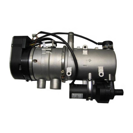
Visit www.butlertechnik.com for more technical information and downloads. 2 General description Thermo Pro 90 General description The Thermo Pro 90 water heater is used in conjunction with The Thermo Pro 90 heater mainly consists of the following the original vehicle heating system in the parking heating components: mode for –... -
Page 10: Fig. 202 Combustion Air Fan
Visit www.butlertechnik.com for more technical information and downloads. Thermo Pro 90 2 General description Combustion air fan 2.2.2 Overheating protection The overheating protection (bi-metal) protects the heater The combustion air fan feeds the air required for combus- against impermissibly high operating temperatures. The tion to the burner unit. -
Page 11: Fig. 205 Burner Head With Combustion Pipe
Visit www.butlertechnik.com for more technical information and downloads. 2 General description Thermo Pro 90 Combustion pipe Circulation pump The combustion pipe supports the combustion of the fuel- The circulation pump ensures the pumping of the coolant in air mixture, and as a result partially also the heating of the the vehicle and/or heater circuit. -
Page 12: Fig. 301
10) Control break 21) Run-on ended 11) "Flame OFF” detection Fig. 301 Operating sequence of Thermo Pro 90 Switching on and residual-heat utilisation phase The heater is switched on depending on the equipment The activation of the residual-heat utilisation phase can only variant by means of a switch or standard timer. -
Page 13: Starting And Control Mode
Visit www.butlertechnik.com for more technical information and downloads. 3 Description of Operation Thermo Pro 90 If the criterion b) is met during the activation of the residual- heat utilisation phase or during the residual-heat utilisation phase, then the heater is automatically started. -
Page 14: Technical Data
Visit www.butlertechnik.com for more technical information and downloads. Thermo Pro 90 4 Technical Data Technical Data Heater Operation Thermo Pro 90 12 V 24 V Approval symbol E1 122R 00 0320 (Heater) E1 10R 03 6196 (EMC) Model Water heater with evaporator-type burner Heat output Max. -
Page 15: Faults, Troubleshooting
The error code is used by the workshop or the authorised Webasto dealer for troubleshooting. NOTE In the Webasto Thermo Test PC Diagnosis, W bus must be selected under “Diagnosis” => “Device selection”. It is rec- ommended that the operating and fault data and the extended fault environment conditions be printed out. - Page 16 Visit www.butlertechnik.com for more technical information and downloads. Thermo Pro 90 5 Faults, Troubleshooting Elimination of faults with Webasto Thermo Test PC Heater lock-out Diagnosis With Webasto Thermo Test PC Diagnosis Switch on heater (switch/standard timer or with Is unlocked as follows: "Parking Heating“...
-
Page 17: Fig. 501 Overview Of Possible Faults
Troubleshooting without error code output Possible faults The overview only shows some of the possible faults. The Webasto Service Hotline must be contacted in individual cases. IMPORTANT The error points specified from Tables Fig. 501 and Fig. 502 DO NOT match the error code numbers for error code output! - Page 18 S4, Pin F to earth – Check fuse F2 DP42 metering Measure fuel feed rate (use Webasto Thermo Test PC Diesel feed rate at metering pump Diagnosis for controlling the metering pump), also pump frequency of 9 Hz and see Section 6.4.5...
- Page 19 Disconnect the fuel line from the heater, hold the hose in a catch container and operate the metering pump with the Webasto Thermo Test PC Diagnosis for 180 s at 9 Hz. When doing so, watch whether the fuel is pumped bubble-free...
- Page 20 Visit www.butlertechnik.com for more technical information and downloads. Thermo Pro 90 5 Faults, Troubleshooting Error point Component Recommended workshop action Parameter Vehicle fan Check fuse F1 Observe coolant temperature (K5 switches at approx. 25 °C) Check switching signal on the relay K5, ground on...
-
Page 21: Fig. 503 Error Code Output By Standard Timer/Switch
Troubleshooting with error code output The error code is displayed via: NOTE – the operation indicator or In the Webasto Thermo Test PC Diagnosis, W bus must be – the "ON/OFF" switch or selected under “Diagnosis” => “Device selection”. It is –... - Page 22 Visit www.butlertechnik.com for more technical information and downloads. Thermo Pro 90 5 Faults, Troubleshooting Error code Fault message Possible causes Recommended workshop action number/ Number of flashing pulses Supply voltage Power supply Check battery too high/Operat- Check electrical connections ing voltage too...
- Page 23 Visit www.butlertechnik.com for more technical information and downloads. 5 Faults, Troubleshooting Thermo Pro 90 Error code Fault message Possible causes Recommended workshop action number/ Number of flashing pulses Exhaust gas tem- Exhaust temperature sensor Check wiring for damage, open circuit and short circuit...
-
Page 24: Fig. 504 Visual Inspection, Rear Wall Of Burner
Visit www.butlertechnik.com for more technical information and downloads. Thermo Pro 90 5 Faults, Troubleshooting Visual inspection for evaluation of burner unit Observe the specific features of the burner unit if it needs to First, the burner unit is checked for completeness and be replaced or no source of error is apparent. -
Page 25: Fig. 505 Visual Inspection, Entire Burner Unit
Visit www.butlertechnik.com for more technical information and downloads. 5 Faults, Troubleshooting Thermo Pro 90 • Fasteners (3x) of metal fibre evaporator are deformed or missing. Therefore, metal fibre evaporator is not pressed on correctly. Remedy Replace burner unit. Combustion chamber... -
Page 26: Operating Tests
Operating checks in vehicle The Thermo Pro 90 is equipped with an automatic altitude compensation function. As a result, the permissible operat- ing altitude for the heater is 0 to 3500 m above sea level. -
Page 27: Checking Individual Components
The reason for this is sensors in the control Measuring accuracy better than ± 5 mohms according to unit which are required for speed control. 4-conductor measuring principle The test is carried out with the related Webasto Thermo Test PC Diagnosis. Speed specification is 6,100 rpm www.butlertechnik.com... -
Page 28: Testing Dp42 Metering Pump
6.4.7 Testing circulation pump The operation of the circulation pump (UP) must be tested with the component test function in the Webasto Thermo Test PC Diagnosis. In addition, operation can also be felt by touching the circulation pump with the hand. When doing so, a constant vibration of the circulation pump must be felt. -
Page 29: Fig. 701 Connector Assignment On Control Unit
Fig. 704 shows the circuit of the Thermo Pro 90 heater, parking heater with On/Off switch without ADR. Fig. 705 shows the circuit of the Thermo Pro 90 heater, parking heater with On/Off switch with ADR with auxiliary drive. Fig. 706 shows the circuit of the Thermo Pro 90 heater, parking heater with On/Off switch with ADR without auxiliary drive. - Page 30 Visit www.butlertechnik.com for more technical information and downloads. Thermo Pro 90 7 Circuit diagrams Table 3 Legend for wiring diagrams Item Description Comment Temperature coding D+ signal (vehicle engine ON/OFF) for determination of the control temperature Standard clock P2 –...
-
Page 31: Fig. 703 Wiring Diagram For Thermo Pro 90, Parking Heater With Standard Timer Without Adr
Visit www.butlertechnik.com for more technical information and downloads. 7 Circuit diagrams Thermo Pro 90 Fig. 703 Wiring diagram for Thermo Pro 90, parking heater with standard timer without ADR. www.butlertechnik.com... -
Page 32: Fig. 704 Circuit Diagram For Thermo Pro 90, Parking Heater With On/Off Switch Without Adr
Visit www.butlertechnik.com for more technical information and downloads. Thermo Pro 90 7 Circuit diagrams Fig. 704 Circuit diagram for Thermo Pro 90, parking heater with On/Off switch without ADR. www.butlertechnik.com... -
Page 33: Fig. 705 Circuit Diagram For Thermo Pro 90, Parking Heater With On/Off Switch With Adr With Auxiliary Drive
Visit www.butlertechnik.com for more technical information and downloads. 7 Circuit diagrams Thermo Pro 90 Fig. 705 Circuit diagram for Thermo Pro 90, parking heater with On/Off switch with ADR with auxiliary drive. www.butlertechnik.com... - Page 34 Visit www.butlertechnik.com for more technical information and downloads. Thermo Pro 90 7 Circuit diagrams Fig. 706 Circuit diagram for Thermo Pro 90, parking heater with On/Off switch with ADR without auxiliary drive. www.butlertechnik.com...
-
Page 35: Work On Vehicle
Visit www.butlertechnik.com for more technical information and downloads. 8 Servicing work Thermo Pro 90 Servicing work This section describes the servicing work that can be carried Checking work out on the heater and its components while installed. In the interest of the operating safety of the heater, the... -
Page 36: Installation
7 Bleed coolant circuit. With the fuel line completely drained, the line must be filled with the Webasto Thermo Test PC Diagnosis: Press the "Fuel 8 Bleed vehicle fuel system if necessary. prime" button and prime line with fuel until fuel is present at the heater. -
Page 37: Maintaining And Replacing Components
Visit www.butlertechnik.com for more technical information and downloads. 9 Maintaining and Replacing Components Thermo Pro 90 Maintaining and Replacing Components General This section describes the permissible repair work on the heater when removed. Any and all warranty claims shall be voided if the heater is dismantled further. -
Page 38: Fig. 901 Replacing Circulation Pump
Visit www.butlertechnik.com for more technical information and downloads. Thermo Pro 90 9 Maintaining and Replacing Components Replacing circulation pump Removal Installation 1. Remove heater (see Section 8.5.1). 1. Coat sealing ring (1, Fig. 901) with acid-free grease 2. Disconnect electrical connections (see Section 9.3). -
Page 39: Replacing Overheating Protection
Visit www.butlertechnik.com for more technical information and downloads. 9 Maintaining and Replacing Components Thermo Pro 90 Replacing overheating protection Replacing coolant temperature sensor Removal Removal NOTE 1. Remove heater (see Section 8.5.1). The overheating protection may only be removed if it is 2. -
Page 40: Fig. 902 Replacing Overheating Protection And Coolant Temperature Sensor
Visit www.butlertechnik.com for more technical information and downloads. Thermo Pro 90 9 Maintaining and Replacing Components 1 = Protective cap 2 = Clamp 3 = Overheating protection 4 = Heat exchanger 5 = Round sealing ring 6 = Coolant temperature sensor Fig. -
Page 41: Fig. 903 Replacing Combustion Air Fan
Visit www.butlertechnik.com for more technical information and downloads. 9 Maintaining and Replacing Components Thermo Pro 90 Replacing combustion air fan Removal Installation 1. Remove heater (see Section 8.5.1), depending on space NOTE required. Ensure intact, moulded-on sealing bead. 2. Disconnect electrical connections (see Section 9.3). -
Page 42: Replacing Burner Unit And Glow Plug
Visit www.butlertechnik.com for more technical information and downloads. Thermo Pro 90 9 Maintaining and Replacing Components Replacing burner unit and glow plug Removal Installation 1. Remove heater (see Section 8.5.1), depending on space 1. Carefully insert glow plug (4) in burner unit (1) as far as required. -
Page 43: Fig. 904 Replacing Burner Unit, Glow Plug, Burner Head And Exhaust Temperature Sensor
Visit www.butlertechnik.com for more technical information and downloads. 9 Maintaining and Replacing Components Thermo Pro 90 1 = Burner unit 7 = Grommet 12 = Hold-down device for exhaust 2 = Burner head 8 = Heat exchanger temperature sensor 3 = Screw... -
Page 44: Replacing Heat Exchanger
Visit www.butlertechnik.com for more technical information and downloads. Thermo Pro 90 9 Maintaining and Replacing Components 9.10 Replacing heat exchanger 9.12 Replacing exhaust temperature sensor Removal Removal 1. Remove heater (see Section 8.5.1). 1. Disconnect electrical connections (see Section 9.3). -
Page 45: Fig. 905 Permissible Bending Angle And Permissible Load
Visit www.butlertechnik.com for more technical information and downloads. 9 Maintaining and Replacing Components Thermo Pro 90 IMPORTANT The exhaust-temperature sensor cable is designed as a high- temperature-resistant line. The material is resistant to continuous effects of tempera- tures of up to 185 °C, however it is sensitive to external mechanical influences. -
Page 46: Fig. 1001 Preferred Position Of Thermo Pro 90 Heater For Storage And Transport
The type label and the surface of the heater must be protected against damage with a suitable surface (e.g. cardboard). Fig. 1001 Preferred position of Thermo Pro 90 heater for storage and transport 1001 www.butlertechnik.com... - Page 47 Germany Visitors’address: Friedrichshafener Str. 9 82205 Gilching Germany Internet: www.webasto.com Technical Extranet: http://dealers.webasto.com The telephone number of each country can be found in the Webasto service center leaflet or the website of the respective Webasto representative of your country. www.butlertechnik.com...
Need help?
Do you have a question about the Thermo Pro 90 and is the answer not in the manual?
Questions and answers