
Related Manuals for MPPT SUN-MPPT-4015A


Summary of Contents for MPPT SUN-MPPT-4015A
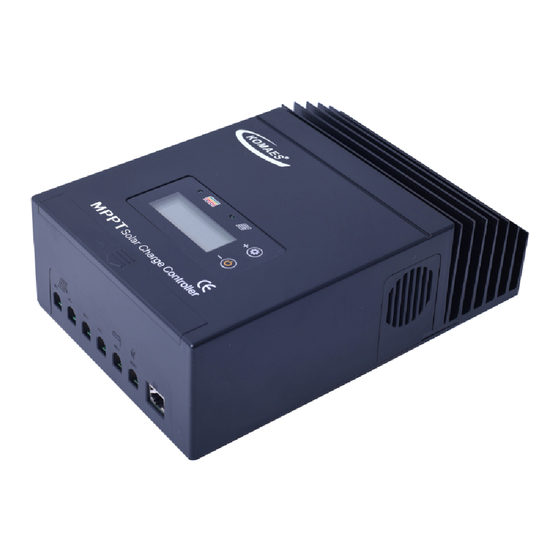
- Page 1 MPPT Solar charge controller Installation and Operation Manual Models SUN-MPPT-4015A...
- Page 2 General Information Wiring Setting operation 5.0 Warranty 6.0 Specifi...
-
Page 3: Dimensions In Millimeters [Inches]
Dimensions in Millimeters [Inches]... -
Page 4: Important Safety Information
• Disconnect all sources of power to the controller before installing or adjusting the MPPT. • There are no fuses or disconnects inside the MPPT. Do not attempt to repair it. • Install external fuses/breakers as required. -
Page 5: General Information
Please take the time to read this operator’s manual and be familiar with the controller. This will help you make full use of the many advantages the MPPT can provide for your PV system. - Page 6 1 - Battery Status LED Indicator An LED indicator that shows battery status or system errors. 2 - Charging Status LED Insdicator An LED indicator that shows charging status and overvoltage of pv. 3 - Setting Button1 Set load work mode,battery type and max charge current. 4 - Setting Button2 Set load work mode,battery type and max charge current(in manual mode used for load ON/OFF).
-
Page 7: Installation
If required, the controller may be in- stalled in a ventilated enclosure with sufficient air flow. Never install the MPPT unit in a sealed enclosure. The controller may be mounted in an enclosure with sealed batteries, but never with vented/ MPPT circuits. - Page 8 1. Attach the mounting hanger to the bottom of the MPPT with the M6 screw provided as shown in figure 3-1. 2. Place the MPPT on a vertical surface protected from direct sunlight, high temperatures, and water. The MPPT requires at least 150 mm of clearance right and left.
- Page 9 Figure 3-3. Load wiring. Step 3: Battery Wiring WARNING: Risk of explosion or fire ! Never short circuit positive(+) and negative(-) or cables Figure 3-4. Battery wiring. ● connect battery positive(+) wire to the positive terminal of the unit and battery negative(-) wire to the negative terminal of the unit.
- Page 10 Figure 3-5.Batteries in series connection 2) Multiple batteries in parallel connection(Refer to Fig.3-6): Each battery’s voltage must be equal to the Nominal DC Voltage of the unit. Figure 3-6.Batteries in parallel connection Step 4: Solar Module Wiring WARNING: Risk of electric shock! Exercise caution when handing solar wiring. The solar array high voltage output can cause severe shock or injury.
- Page 11 Use #6 to #7 AWG wire rated for 75º C for Solar connections. Model Nominal DC Voltage Maximum Solar Module Power MPPT-4015A 12/24 VDC 560/1120 W Table 3-1 Maximum solar module power 2) Multiple solar modules in parallel connection(Refer to Fig.7): Each module’s voltage must be equal to the nominal DC Voltage of the unit.
-
Page 12: Operation
44 Amps of charge current flowing out to the battery.The MPPT does not create current! Rest assured that the power into the MPPT is the same as the power out of the MPPT. Since power is the product of voltage and current (Volts x Amps), the... - Page 13 In this situation, there will be very little or no MPPT gain compared to traditional controllers. However, systems with modules of higher nominal voltage than the battery bank will always have an array V greater than battery voltage.
-
Page 14: Equalize Stage
Equalize Stage WARNING: Risk of Explosion Equalizing vented batteries produces explosive gases. The battery bank must be properly ventilated. CAUTION: Equipment Damage Equalization increases the battery voltage to levels that may damage sensitive DC loads. Verify all system loads are rated for the temperature compensated Equalize voltage before beginning an Equalization charge. -
Page 15: Battery Charging Information
4.2 Battery Charging Information 4-Stage Charging The MPPT has a 4-stage battery charging algorithm for rapid, eff cient, and safe battery charging. Figure 4-2 shows the sequence of the stages. EQUALIZE FLOAT ABSORPTION BULK CHARGE TIME Figure 4-2. MPPT charging algorithm... -
Page 16: Led Indications
4.3 LED Indications ● Charging Indicator The green LED indicator will light whenever sunlight is available for battery charging, the green charging LED will stay on in normal charging. The charging LED indicator flashes when PV over voltage. Charging LED Indicator Table4-1 Color Indication... -
Page 17: Setting Operation
4.3 Setting operation Battery icon Solar icon Load icon Battery Voltage Data Indicator There are 4 parameters can be set in Load Work Setting Mode: 1F(Optical delay), 2F(Optical),3F(Battery type),4F(Maximum charging current) Press “KEY 1”hold for 3 seconds enters the setting mode, then press KEY 1, the LCD will switch over between 1F,2F,3F,4F.Press KEY 2,when “... - Page 18 ● Load Control Setting(Setting Mode 1F00 and 2F00) 1. Dusk to Dawn (Light ON + Light OFF) When solar module voltage goes below the point of NTTV (Night Time Threshold Voltage) at sunset, the solar controller will recognize the starting voltage and turn on the load after 10 minutes delay;...
- Page 19 ● Battery Setting(Setting Mode 3FB1) Battery type LCD dispaly Sealed lead acid battery 3Fb1 Gel battery 3Fb2 AGM battery 3Fb3 Flooded battery 3Fb4 ● Maximum charging Setting(Setting Mode 3FB1) The default maximum charging current is 40A,customers can set the maximum charging current depend on themselves requirement.
-
Page 20: Warranty
5.0 Warranty The MPPT charge controller is warranted to be free from defects in material and work-manship for a period of TWO(2) years from the date of shipment to the original end user. We will, at its option, repair or replace any such defective products. -
Page 21: Specifications
Specifications Electrical SUN-MPPT-4015A Characterisation of the operating performance system Voltages 12V/24V/48V 12VDC 630 Watts Maximum Solar Array 24VDC 1260watts/48VDC 2688watts Standby Power Consumption Less than 1 Watt typical Peak Efficiency DC input side PV Open Circuit Voltage (VOC) 150 volts DC...
Need help?
Do you have a question about the SUN-MPPT-4015A and is the answer not in the manual?
Questions and answers