Table of Contents
Advertisement
Advertisement
Table of Contents

Related Manuals for Kärcher HD 6/15-4


Summary of Contents for Kärcher HD 6/15-4
- Page 1 HD 6/15-4, HD 7/11-4 Service Manual English 5.906-565.0 Rev. 00 (12/12)
-
Page 2: Table Of Contents
Contents Contents............2 Preface . - Page 3 7.16.3 Dismantling the drive ........
-
Page 4: Preface
Danger This service manual describes the following applianc- Risk of electric shock. Prior to opening the electric casing, the appliance HD 6/15-4 must be de-energised (pull the mains plug) and se- HD 7/11-4 cured against accidental restart. English 5.906-565.0 Rev. 00 (12/12) -
Page 5: Type Plate
5.7 Type plate The type plate is located on the right side of the ap- pliance. 1 Part number 2 Year of manufacture 3 Type of protection 4 Typical operating weight 5 Flow rate 6 Nozzle size 7 Max. feed temperature 8 Address of manufacturer 9 Bar code. -
Page 6: Parts Of The System
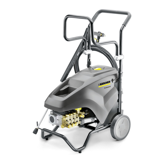
Parts of the system 6.1 Overview 1 Push handle 9 Cover 2 High pressure hose 10 Spray lance 3 Machine frame 11 Power switch 4 Wheel 12 Trigger gun 5 Waterfilter 13 Rotary coupling 6 High pressure connection 7 High pressure pump 8 Nozzle screws Power nozzle English 5.906-565.0 Rev. - Page 7 1 Trigger gun storage clip 2 Oil level indicator 3 Oil drain screw 4 Storage for spray pipe 5 Step depression 6 Nameplate 7 Water connection 8 Mains cable with mains plug 9 Cable hook, rotating 10 Storage compartment for hoses English 5.906-565.0 Rev.
- Page 8 1 Cover 2 Storage compartment 3 Water connection 4 Motor 5 Pressure and volume regulation 6 Cylinder head 7 Crankcase 8 Oil fill screw 9 Flange 10 Storage compartment for nozzles English 5.906-565.0 Rev. 00 (12/12)
- Page 9 1 Power switch 2 Water drain 3 Startup capacitor 4 Operating capacitor 5 Resistor 6 Connection terminals 7 Cable from the motor, 5 wires 8 Cord grip 9 Power cable, 3 wires 10 Cable from the pressure switch English 5.906-565.0 Rev. 00 (12/12)
-
Page 10: Basic Settings And Service Procedures
Basic settings and service procedures Danger First pull out the plug from the mains before carrying out any tasks on the machine. Activate hand spray gun until device is pressure less. 7.1 Overview appliance components 7.1.1 Frame English 5.906-565.0 Rev. 00 (12/12) -
Page 11: Motor
7.1.2 Motor 7.1.3 Crank drive A Locking screw (delivery condition) B Ventilation screw (operation) English 5.906-565.0 Rev. 00 (12/12) - Page 12 English 5.906-565.0 Rev. 00 (12/12)
-
Page 13: Cylinder Head
7.1.4 Cylinder head English 5.906-565.0 Rev. 00 (12/12) - Page 14 English 5.906-565.0 Rev. 00 (12/12)
-
Page 15: Remove The Appliance Cover
7.2 Remove the appliance cover 7.3 Oil change Note See "Technical Details" for details of oil quantity and type. Open the device hood. Unscrew oil drain plug. Drain the oil in a collection basin. Fix in the oil drain screw and tighten it. Torque 20...25 Nm. -
Page 16: Clean Water Filter
7.4 Clean water filter. 7.5 Replacing the water connection Unscrew the covering nut. Loosen the hose clip. Unscrew the filter casing. Pull out the hose. Take out the filter inlay. Unscrew 2 screws. ... -
Page 17: Removing The Pressure Switch
7.6 Removing the pressure switch 7.7 Dismantling the cylinder head Pull down circlip. Disconnect the water supply hose from the cylin- der head. Remove the pressure switch. Note: Should you wish to replace the valves of the pump as well, perform the following steps prior to dismantling the cylinder head: Loosen the valve screws (see "Replacing valves"). -
Page 18: Replacing The High And Low Pressure Gaskets
7.8.2 Replace high pressure seals 7.8 Replacing the high and low pressure gaskets 7.8.1 Replace the low pressure seals Dismount cylinder head (see "Dismounting the cylinder head"). Dismantle the high pressure gasket packages by means of valve pliers. 1 Crankcase ... -
Page 19: Installing The Cylinder Head
Push the sealing ring onto the installation mandrel Insert both discs of the high pressure gasket pack- (special tool). age in the cylinder head together. 7.8.3 Installing the cylinder head Place the installation sleeve on the cylinder head. ... -
Page 20: Replacing The Valves
7.9 Replacing the valves 7.10 Checking the pressure retaining valve 1 Valve screw Unscrew the connecting piece. 2 Valve Remove the check valve. 3 O ring 4 Screwed sealing plug Unscrew the valve screws. Remove the valve and O-ring. ... -
Page 21: Checking The Overflow Valve
7.11 Checking the overflow valve Clean valve seat. Check valve seat for wear. Pull off the rotary handle. Dismantle the worn valve seat by means of valve pliers. Unscrew the overflow valve (wrench size 32 mm). ... -
Page 22: Adjusting The Overflow Valve
Open the hand spray gun. Adjust the adjustment nut until the following work- ing pressure is displayed: HD 6/15-4 16.0...16.4 MPa (160...164 bar) HD 7/11-4 12.0...12.4 MPa (120...124 bar) Open and close the hand spray gun 3 times while the motor is running. -
Page 23: Check / Replace The Mechanics Of The Pressure Switch
7.13 Check / replace the mechanics of the 7.14 Replacing the ceramic piston pressure switch Dismount cylinder head (see "Dismounting the cylinder head"). Pull the low pressure gaskets off the piston (see "Replacing high and low pressure gaskets/replac- ing low pressure gaskets"). -
Page 24: Dismantling The Pump
7.15 Dismantling the pump 7.16 Replacing the oil seals Disconnect the water supply hose from the cylin- Dismount cylinder head (see "Dismounting the der head. cylinder head"). (See "Dismantling the cylinder head".) 7.16.1Draining the oil Remove the pressure switch. ... -
Page 25: Dismantling The Drive
7.16.3Dismantling the drive 1 Cover 2 Bearing cover Mark the bearing shells (in the example: 1, 2, 3). Loosen 6 screws. Loosen 4 screws. Remove the lid. Remove the bearing shells. Mark the piston rods (in the example: 1 dot, 2 dots, Caution 3 dots). -
Page 26: Dismantling The Crankshaft
7.16.4Dismantling the crankshaft Caution Risk of damage for the ball bearing. Choose the di- ameter of the pressing mandrel so that the press-in force acts on the outer ring of the ball bearing. Press a new ball bearing into the crankshaft cas- ing. -
Page 27: Installing The Crankshaft
Clean and check the gasket seat. 7.16.6Installing the crankshaft Caution Risk of damage for the ball bearing. When pressing the crankshaft in, support the ball bearing at the inner and outer ring. Insert the crankshaft in the crankshaft casing and press it in in small steps. - Page 28 Refill fresh oil. The oil level is checked at the sight gauge, the lev- el should be at least up to the middle of the sight gauge. 1 O ring Replace O-ring. Attach the flange on the crankshaft casing. ...
-
Page 29: Open The Electric Casing
7.17 Open the electric casing 7.18 Replace appliance switch Danger Opening the electric casing (see "Opening the electric casing") Risk of electric shock. Prior to opening the electric casing, the appliance must be de-energised (pull the mains plug) and se- cured against accidental restart. -
Page 30: Replacing The Mains Cable
7.19 Replacing the mains cable Reconnect the cable from the old to the new switch. 1 Back panel Reinstall the switch and the rotary knob. Loosen 4 screws. Close the electric casing. Remove back panel. ... -
Page 31: Access To The Terminal Box Of The Electric Motor
7.20 Access to the terminal box of the elec- tric motor Dismantle the push handle (2 screws) and remove Remove pressure switch (see "Removing the pressure switch"). Loosen 4 screws. Remove the lid. Loosen 4 screws. ... -
Page 32: Replacing The Electric Motor
7.21 Replacing the electric motor Danger Risk of electric shock. Prior to opening the electric casing, the appliance must be de-energised (pull the mains plug) and se- cured against accidental restart. Remove the high pressure pump from the electric motor. -
Page 33: Troubleshooting
Troubleshooting 8.1 Appliance is not running Check connection cable for damages. Check the supply voltage. Check/replace the appliance switch. Check/replace the pressure switch 8.2 Pressure does not build up in the appli- ance Set the pressure and quantity regulation to "MAX". (Turn in a clockwise direction to the stop). -
Page 34: Technical Documentation
Technical Documentation Appliance type Appliance no.: Operating in- Spare parts Circuit dia- structions list gram HD 6/15-4 1.367-301.0 5.964-718.0 9.761-167.0 9.761-243.0 HD 7/11-4 1.367-302.0 9.1 Technical specifications Type HD 6/15-4 HD 7/11-4 1.367-302.0 1.367-301.0 Main Supply Voltage 220...240 Current type... -
Page 35: Special Tools
9.2 Special tools Electric measuring appliance 6.803-022.0 Shut-off valve with thermometer 2.901-030.0 Removal pliers, pressure/suction 4.901-062.0 Installation mandrel oil seal 2.901-033.0 valves and water sieves Installation mandrel high pressure 5.901-227.0 gasket Installation sleeve, high pressure seal 5.901-226.0 Test manometer for working pres- 4.401-072.0 Test nozzle 25018 for HD 6/15 and HD 5.765-092.0... -
Page 36: Circuit Diagram
9.4 Circuit diagram The circuit diagram in the service manual is not up- When working on the device, please always use the dated. current circuit diagram in DISIS. English 5.906-565.0 Rev. 00 (12/12)
Need help?
Do you have a question about the HD 6/15-4 and is the answer not in the manual?
Questions and answers