Table of Contents

Subscribe to Our Youtube Channel
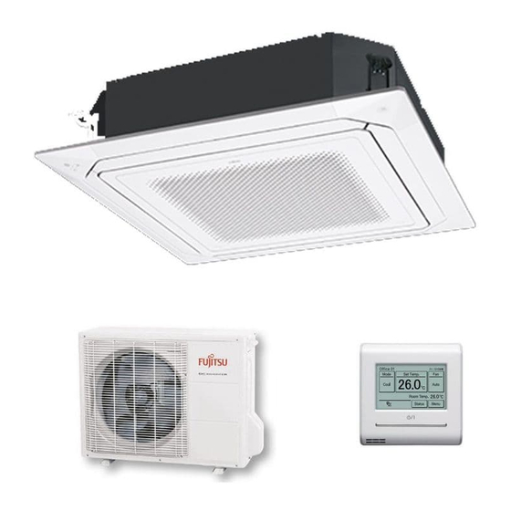
Related Manuals for Fujitsu AUXG18LRLB


Summary of Contents for Fujitsu AUXG18LRLB
-
Page 1: Air Conditioner
AIR CONDITIONER Cassette type DESIGN & TECHNICAL MANUAL INDOOR AUXG18LRLB AUXG36LRLB AUXG24LRLB AUXG45LRLB AUXG30LRLB AUXG54LRLB OUTDOOR AOYG18LBCA AOYG30LBTA AOYG45LBTA AOYG24LBCA AOYG36LBTA AOYG54LBTA DR_AU002EF_03 2016.02.09... - Page 2 Notices: • Product specifications and design are subject to change without notice for future improvement. • For further details, please check with our authorized dealer. Copyright © 2015, 2016 Fujitsu General Limited. All rights reserved.
-
Page 3: Table Of Contents
2-2. Overview ........................9 2-3. Specifications ......................10 2-4. Wiring specifications ....................10 3. Specifications ..................11 3-1. Models: AUXG18LRLB and AUXG24LRLB .............11 3-2. Models: AUXG30LRLB, AUXG36LRLB, AUXG45LRLB, and AUXG54LRLB ..13 4. Dimensions ....................15 4-1. Models: AUXG18LRLB and AUXG24LRLB .............15 4-2. Models: AUXG30LRLB, AUXG36LRLB, AUXG45LRLB, and AUXG54LRLB ..17 4-3. - Page 4 CONTENTS (continued) 12-1.Remote controller address setting ................74 12-2.Remote controller master/slave setting ..............76 12-3.Memory backup setting ..................76 13. Optional parts ..................77 13-1.Controllers ......................77 13-2.Cassette grille ......................78 13-3.Others ........................78...
- Page 5 CONTENTS (continued) Part 2. OUTDOOR UNIT ..............81 1. Specifications ..................82 1-1. Models: AOYG18LBCA and AOYG24LBCA ............82 1-2. Models: AOYG30LBTA and AOYG36LBTA ............83 1-3. Models: AOYG45LBTA and AOYG54LBTA ............84 2. Dimensions ....................85 2-1. Models: AOYG18LBCA and AOYG24LBCA ............85 2-2. Models: AOYG30LBTA and AOYG36LBTA ............86 2-3.
- Page 6 CONTENTS (continued) 10. Safety devices ..................119 11. External input and output (Only for ) ...121 AOYG45LBTA and AOYG54LBTA 11-1.External input ......................121 11-2.External output ..................... 123 12. Function settings (Only for ) ....125 AOYG45LBTA and AOYG54LBTA 12-1.Local setting switch buttons .................. 125 12-2.Local setting procedure ..................
-
Page 7: Part 1. Indoor Unit
Part 1. INDOOR UNIT CASSETTE TYPE: AUXG18LRLB AUXG24LRLB AUXG30LRLB AUXG36LRLB AUXG45LRLB AUXG54LRLB... -
Page 8: Product Features
1. Product features Implemented core technology provides easy-to-use product operations that realize a comfortable space. 1-1. Model lineup AUXG18LRLB AOYG18LBCA AOYG30LBTA AOYG45LBTA AUXG24LRLB AOYG24LBCA AOYG36LBTA AOYG54LBTA AUXG30LRLB AUXG36LRLB AUXG45LRLB AUXG54LRLB 1-2. Features Energy efficiency class MODEL AUXG18LRLB AUXG24LRLB AUXG30LRLB... -
Page 9: Quiet Operation
Advancement in comfort Quiet operation Twist-blade fan Reduce sound level by decreasing spiral airflow! Individual airflow provides free air conditioning • Individual airflow can be controlled by wired remote controller. • Individual airflow also can be controlled in any positions. Case study: Comfortable air conditioning Efficient air conditioning... -
Page 10: Economy Operation
Economy operation Limits the maximum operation current, and the power consumption is cut down and the maxi- mum load is suppressed. Normal operation Setting temperature Economy operation Time Improvement of installation and maintenance High lift drain pump Ceiling panel 850 mm ... -
Page 11: Wired Remote Controller
2. Wired remote controller 2-1. Features • Easy finger touch operation with LCD panel • Built-in weekly/daily timer (on/off, temperature and mode) • The backlit LCD enables easy operation in a dark room. • Room temperature display • Control up to 16 indoor units •... - Page 12 Various energy saving control • Auto-off timer – The indoor unit automatically turns off after the set time has passed. – The time interval for which auto-off works can be set. Example: At interval time hour (17:00 to 24:00) to prevent forgetting to turn off. Set interval time hour (17:00 to 24:00) Auto-off Set off time...
- Page 13 Various convenient functions • Displays setting status and limitations The remote controller settings can be easily Status Page 1/ 4 Status Page 2/ 4 checked. Air Flow Direction R.C. Prohibition Special State Individual • Under Maintenance Economy • Forced Stop •...
-
Page 14: System Diagram
Backlit LCD • The backlit LCD enables easy operation in a dark room. • Backlighting time can be selected from 30 or 60 seconds. • The backlight is lit while the buttons are operated, and goes off 30 or 60 seconds after the operation stops. -
Page 15: Overview
2-2. Overview a Remote temperature sensor (inside) b On/off button Operable only while displaying the “Monitor mode” screen. c LED lamp (operation indicator) d Touch panel display e Set temperature Operating temperature can be set. f Remote controller group name g Mode Operation mode can be set. -
Page 16: Specifications
2-3. Specifications Dimensions and other specifications on the wired remote controller are as follows. [Unit : mm] 20.4 Display 3.8-inch FSTN LCD (255 × 160 dots) with touch panel Dimensions (H × W × D) 120 × 120 × 20.4 Weight Input voltage DC 12... -
Page 17: Specifications
3. Specifications 3-1. Models: AUXG18LRLB and AUXG24LRLB Cassette Type Inverter heat pump Model name AUXG18LRLB AUXG24LRLB Power supply 230 V ~ 50 Hz Available voltage range 198—264 V Rated Btu/h 17,700 23,200 Cooling 0.90—6.50 0.90—8.00 Min.—Max. Btu/h 3,100—22,200 3,100—27,300 Capacity... - Page 18 Cassette Type Inverter heat pump Model name AUXG18LRLB AUXG24LRLB Remote controller type Wired (Wireless [option]) NOTES: Specifications are based on the following conditions: –Cooling: Indoor temperature of 27 °CDB/19 °CWB, and outdoor temperature of 35 °CDB/24 °CWB. –Heating: Indoor temperature of 20 °CDB/15 °CWB, and outdoor temperature of 7 °CDB/6 °CWB.
-
Page 19: Models: Auxg30Lrlb, Auxg36Lrlb, Auxg45Lrlb, And Auxg54Lrlb
3-2. Models: AUXG30LRLB, AUXG36LRLB, AUXG45LRLB, and AUXG54LRLB Cassette Type Inverter heat pump Model name AUXG30LRLB AUXG36LRLB AUXG45LRLB AUXG54LRLB Power supply 230 V ~ 50 Hz Available voltage range 198—264 V 12.5 13.3 Rated Btu/h 29,000 32,400 42,700 45,400 Cooling 2.8—10.0 2.8—11.2 4.0—14.0 4.5—14.5... - Page 20 Cassette Type Inverter heat pump Model name AUXG30LRLB AUXG36LRLB AUXG45LRLB AUXG54LRLB Remote controller type Wired (Wireless [option]) NOTES: Specifications are based on the following conditions: –Cooling: Indoor temperature of 27 °CDB/19 °CWB, and outdoor temperature of 35 °CDB/24 °CWB. –Heating: Indoor temperature of 20 °CDB/15 °CWB, and outdoor temperature of 7 °CDB/6 °CWB. –Pipe length: 5 m, Height difference: 0 m.
-
Page 21: Dimensions
4. Dimensions 4-1. Models: AUXG18LRLB and AUXG24LRLB Ceiling opening and hanging bolt pitch Unit: mm 950 (Panel frame) 20–45 860–910 (Ceiling opening) 20–45 840 (Body frame) 796 (Hanging bolt pitch) Refrigerant piping and drain piping positions Unit: mm... - Page 22 Airflow split-flow duct and fresh-air inlet positions Unit: mm Airflow split-flow duct connecting port Refrigerant pipe Drain pipe Cut out 3.2 hole Detailed diagram of branched duct connecting port (4 sides) Cut out Knockout hole pitch Fresh air inlet position Airflow split-flow duct connecting port 3.2 hole Fresh air inlet position...
-
Page 23: Models: Auxg30Lrlb, Auxg36Lrlb, Auxg45Lrlb, And Auxg54Lrlb
4-2. Models: AUXG30LRLB, AUXG36LRLB, AUXG45LRLB, and AUXG54LRLB Ceiling opening and hanging bolt pitch Unit: mm 950 (Panel frame) 20–45 860–910 (Ceiling opening) 20–45 840 (Body frame) 796 (Hanging bolt pitch) Refrigerant piping and drain piping positions Unit: mm Drain pipe (Connect the attached drain hose) - 17 -... - Page 24 Airflow split-flow duct and fresh-air inlet positions Unit: mm Airflow split-flow duct connecting port Refrigerant pipe Drain pipe Cut out 3.2 hole Detailed diagram of branched duct connecting port (4 sides) Cut out Knockout hole pitch Fresh air inlet position Airflow split-flow duct connecting port 3.2 hole Fresh air inlet position...
-
Page 25: Installation Space Requirement
4-3. Installation space requirement Provide sufficient installation space for product safety. For 4-direction setting (AUXG18LRLB and AUXG24LRLB): Unit: mm Strong and durable ceiling 256 or more 1,500 3,000 or more or more Ceiling height Ceiling mode* “Low” : 2.7 m Ceiling mode “Standard”... - Page 26 For 3-direction setting: Unit: mm 100 or more NOTES: • To set “3-direction”, optional Air outlet shutter plate (UTR-YDZK) must be installed, and the “outlet-direction” need to be switched to “3-way” by remote controller. • The ceiling height cannot be set in the 3-way outlet mode. Therefore, ceiling height setting change by function setting 20 is prohibited.
-
Page 27: Wiring Diagram
5. Wiring diagram 5-1. Models: AUXG18LRLB, AUXG24LRLB, AUXG30LRLB, AUXG36LRLB, AUXG45LRLB, and AUXG54LRLB - 21 -... -
Page 28: Capacity Table
For cooling capacity: Total Capacity (TC), Sensible Heat Capacity (SHC), and Input Power (IP) For heating capacity: Total Capacity (TC) and Input Power (IP) 6-1. Cooling capacity NOTE: Values mentioned in the table are calculated based on the maximum capacity. Model: AUXG18LRLB 1,050 Indoor temperature °CDB °CWB... - Page 29 Model: AUXG30LRLB 1,600 Indoor temperature °CDB °CWB °CDB 8.67 6.58 1.20 9.66 6.62 1.22 9.99 7.20 1.22 10.65 7.22 1.22 10.98 7.80 1.24 11.64 7.77 1.25 12.29 8.27 1.27 8.52 6.38 1.64 9.49 6.42 1.66 9.81 6.98 1.67 10.46 7.00 1.69 10.79...
- Page 30 Model: AUXG54LRLB 2,100 Indoor temperature °CDB °CWB °CDB 11.73 9.03 2.69 13.07 9.08 2.73 13.52 9.87 2.75 14.41 9.90 2.78 14.85 10.69 2.79 15.74 10.65 2.82 16.64 11.35 2.85 11.72 9.04 2.59 13.06 9.10 2.63 13.50 9.89 2.64 14.39 9.92 2.67 14.84...
-
Page 31: Heating Capacity
6-2. Heating capacity NOTE: Values mentioned in the table are calculated based on the maximum capacity. Model: AUXG18LRLB 1,050 Indoor temperature °CDB °CDB °CWB 5.37 2.41 5.25 2.46 5.12 2.50 4.99 2.55 4.86 2.61 6.18 2.51 6.03 2.57 5.89 2.62... - Page 32 Model: AUXG36LRLB 1,900 Indoor temperature °CDB °CDB °CWB 9.63 3.92 9.40 4.00 9.17 4.08 8.94 4.17 8.71 4.25 9.70 3.96 9.47 4.04 9.24 4.13 9.01 4.21 8.77 4.29 10.69 4.07 10.43 4.16 10.18 4.24 9.92 4.33 9.67 4.41 12.54 3.99 12.24 4.08...
-
Page 33: Fan Performance
7. Fan performance 7-1. Air velocity distributions Model: AUXG18LRLB (4-way air outlet) Fan speed Operation mode Measuring conditions HIGH Unit: m/s Top view 0.25 0.25 Vertical airflow direction louver: position 1 Unit: m/s 0.25 0.25 Side view Vertical airflow direction louver: position 1... - Page 34 Model: AUXG24LRLB (4-way air outlet) Fan speed Operation mode Measuring conditions HIGH Unit: m/s 0.25 Top view 0.25 Vertical airflow direction louver: position 1 Unit: m/s 0.25 0.25 Side view Vertical airflow direction louver: position 1 Unit: m/s Side view Vertical airflow direction louver: position 2 0.25 0.25...
- Page 35 Model: AUXG30LRLB (4-way air outlet) Fan speed Operation mode Measuring conditions HIGH Unit: m/s 0.25 0.25 Top view Vertical airflow direction louver: position 1 Unit: m/s 0.25 0.25 Side view Vertical airflow direction louver: position 1 Unit: m/s Side view Vertical airflow direction louver: position 2 0.25 0.25...
- Page 36 Model: AUXG36LRLB (4-way air outlet) Fan speed Operation mode Measuring conditions HIGH Unit: m/s 0.25 Top view 0.25 Vertical airflow direction louver: position 1 Unit: m/s 0.25 0.25 Side view Vertical airflow direction louver: position 1 Unit: m/s Side view Vertical airflow direction louver: position 2 0.25 0.25...
- Page 37 Model: AUXG45LRLB (4-way air outlet) Fan speed Operation mode Measuring conditions HIGH Unit: m/s Top view Vertical airflow direction louver: position 1 0.25 0.25 Unit: m/s 0.25 0.25 Side view Vertical airflow direction louver: position 1 Unit: m/s Side view Vertical airflow direction louver: position 2 0.25 0.25...
- Page 38 Model: AUXG54LRLB (4-way air outlet) Fan speed Operation mode Measuring conditions HIGH Unit: m/s 0.25 0.25 Top view Vertical airflow direction louver: position 1 Unit: m/s 0.25 0.25 Side view Vertical airflow direction louver: position 1 Unit: m/s Side view Vertical airflow direction louver: position 2 0.25 0.25...
- Page 39 Model: AUXG18LRLB (3-way air outlet) Fan speed Operation mode Measuring conditions HIGH Unit: m/s Top view 0.25 Vertical airflow direction louver: position 1 0.25 Unit: m/s 0.25 0.25 Side view Vertical airflow direction louver: position 1 Unit: m/s Side view Vertical airflow direction louver: position 2 0.25...
- Page 40 Model: AUXG24LRLB (3-way air outlet) Fan speed Operation mode Measuring conditions HIGH Unit: m/s Top view 0.25 Vertical airflow direction louver: position 1 0.25 Unit: m/s 0.25 0.25 Side view Vertical airflow direction louver: position 1 Unit: m/s Side view Vertical airflow direction louver: position 2 0.25 0.25...
- Page 41 Model: AUXG30LRLB (3-way air outlet) Fan speed Operation mode Measuring conditions HIGH Unit: m/s 0.25 Top view Vertical airflow direction louver: position 1 0.25 Unit: m/s 0.25 0.25 Side view Vertical airflow direction louver: position 1 Unit: m/s Side view Vertical airflow direction louver: position 2 0.25 0.25...
- Page 42 Model: AUXG36LRLB (3-way air outlet) Fan speed Operation mode Measuring conditions HIGH Unit: m/s Top view 0.25 Vertical airflow direction louver: position 1 0.25 Unit: m/s 0.25 0.25 Side view Vertical airflow direction louver: position 1 Unit: m/s Side view Vertical airflow direction louver: position 2 0.25 0.25...
- Page 43 Model: AUXG45LRLB (3-way air outlet) Fan speed Operation mode Measuring conditions HIGH Unit: m/s 0.25 Top view Vertical airflow direction louver: position 1 0.25 Unit: m/s 0.25 0.25 Side view Vertical airflow direction louver: position 1 Unit: m/s Side view Vertical airflow direction louver: position 2 0.25 0.25...
- Page 44 Model: AUXG54LRLB (3-way air outlet) Fan speed Operation mode Measuring conditions HIGH Unit: m/s 0.25 Top view Vertical airflow direction louver: position 1 0.25 Unit: m/s 0.25 0.25 Side view Vertical airflow direction louver: position 1 Unit: m/s Side view Vertical airflow direction louver: position 2 0.25 0.25...
-
Page 45: Airflow
7-2. Airflow Model: AUXG18LRLB (4-way outlet) Cooling/Heating Fan speed Airflow 1,050 HIGH QUIET Model: AUXG24LRLB (4-way outlet) Cooling/Heating Fan speed Airflow 1,150 HIGH 1,050 QUIET - 39 -... - Page 46 Model: AUXG30LRLB (4-way outlet) Cooling/Heating Fan speed Airflow 1,600 HIGH 1,400 1,270 1,150 QUIET Model: AUXG36LRLB (4-way outlet) Cooling/Heating Fan speed Airflow 1,900 HIGH 1,118 1,590 1,420 1,180 QUIET Model: AUXG45LRLB (4-way outlet) Cooling/Heating Fan speed Airflow 2,000...
- Page 47 Model: AUXG54LRLB (4-way outlet) Cooling/Heating Fan speed Airflow 2,100 HIGH 1,236 1,780 1,048 1,600 1,320 QUIET - 41 -...
- Page 48 Model: AUXG18LRLB (3-way outlet) Cooling/Heating Fan speed Airflow HIGH QUIET Model: AUXG24LRLB (3-way outlet) Cooling/Heating Fan speed Airflow 1,000 HIGH QUIET - 42 -...
- Page 49 Model: AUXG30LRLB (3-way outlet) Cooling/Heating Fan speed Airflow 1,390 HIGH 1,220 1,100 1,000 QUIET Model: AUXG36LRLB (3-way outlet) Cooling/Heating Fan speed Airflow 1,660 HIGH 1,390 1,240 1,030 QUIET Model: AUXG45LRLB (3-way outlet) Cooling/Heating Fan speed Airflow 1,740 HIGH...
- Page 50 Model: AUXG54LRLB (3-way outlet) Cooling/Heating Fan speed Airflow 1,830 HIGH 1,078 1,550 1,390 1,150 QUIET - 44 -...
-
Page 51: Fresh-Air Characteristics
7-3. Fresh-air characteristics Airflow volume: static pressure of fresh-air intake characteris- tics Duct (inside diameter: ø 95 mm) Duct fan Static pressure required to take in fresh-air Airflow (m Installation Unit: mm Top view Refrigerant pipe Drain pipe 2.5 screw hole (4 places) Cut-out hole View (A) -
Page 52: Duct Connection
7-4. Duct connection Outlet air Duct (inside size: 350 mm 100 mm) Model: AUXG18LRLB Fan Speed Quiet 1-way Fan Speed Fan Speed Fan Speed High 1-way Quiet 2-way High 2-way L=10m L=5m L=1m Airflow (m /min) Model: AUXG24LRLB... - Page 53 Model: AUXG36LRLB Fan Speed High 1-way Fan Speed High 2-way Fan Speed Quiet 1-way L=10m Fan Speed Quiet 2-way L=5m L=1m Airflow (m /min) Model: AUXG45LRLB Fan Speed High 1-way Fan Speed High 2-way Fan Speed Quiet 1-way Fan Speed L=10m Quiet 2-way...
- Page 54 Precautions on air-outlet duct connection • Connect the air-outlet duct to maximum 2 directions among the 4-duct connecting directions. CAUTION Do not connect ducts at 3 or more directions. • When installing air-outlet duct in 2 directions, connect the ducts in a straight line. Air-outlet duct Close Close...
-
Page 55: Operation Noise (Sound Pressure)
8. Operation noise (sound pressure) 8-1. Noise level curve Ceiling height Outlet directions Measuring conditions Standard 4-way air outlet Model: AUXG18LRLB Cooling Heating NC-65 NC-65 NC-60 NC-60 NC-55 NC-55 NC-50 NC-50 NC-45 NC-45 High High NC-40 NC-40... - Page 56 Model: AUXG30LRLB Cooling Heating NC-65 NC-65 NC-60 NC-60 NC-55 NC-55 NC-50 NC-50 NC-45 NC-45 High High NC-40 NC-40 NC-35 NC-35 NC-30 NC-30 Quiet Quiet NC-25 NC-25 NC-20 NC-20 NC-15 NC-15 1000 2000 4000 8000 1000 2000 4000 8000 Octave band center frequency ,Hz Octave band center frequency ,Hz...
- Page 57 Model: AUXG45LRLB Cooling Heating NC-65 NC-65 NC-60 NC-60 NC-55 NC-55 NC-50 NC-50 High High NC-45 NC-45 NC-40 NC-40 NC-35 NC-35 Quiet NC-30 NC-30 Quiet NC-25 NC-25 NC-20 NC-20 NC-15 NC-15 1000 2000 4000 8000 1000 2000 4000 8000 Octave band center frequency ,Hz Octave band center frequency ,Hz...
-
Page 58: Sound Level Check Point
8-2. Sound level check point Microphone Center 1.5 m Microphone Center - 52 -... -
Page 59: Safety Devices
9. Safety devices Model Type of protection Protection form AUXG18LRLB AUXG24LRLB Current fuse Circuit protection 250 V, 3.15 A (PCB*) 125 ± 10 °C Activate Fan motor stop Fan motor Thermal protection protection program 120 ± 10 °C Reset Fan motor restart... -
Page 60: External Input And Output
10. External input and output Rotary switch CN65 CN47 (Ext.in/out PCB) (Ext.out) Terminal (Ext.in) Fig. Indoor unit PCB Fig. External input and output PCB External Input External input External output Connector Input select connect kit signal (Optional parts) Operation/Stop Terminal Dry contact Edge Operation status... - Page 61 External input and output PCB The indoor unit Operation/Stop can be set by using the input terminal on the PCB. Input select Use either one of these types of terminals according to the application. (Both types of terminals cannot be used simultaneously.) •...
-
Page 62: 10-2.External Output
10-2. External output Use an external output cable with appropriate external dimension, depending on the number of ca- bles to be installed. Indoor unit • A twisted pair cable (22AWG) should be used. Maximum length of cable is 25 m. •... -
Page 63: 10-3.Combination Of External Input And Output
10-3. Combination of external input and output By combining the function setting of the indoor unit and rotary switch setting of the External input and output PCB, you can select various combinations of functions. Combination examples of external input and output are as follows: External input External Function... - Page 64 Input signal type • Indoor unit Input signal type is only "Edge". Edge • External input and output PCB The input signal type can be selected. Signal type (edge or pulse) can be switched by the DIP switch 2 (SW2) on the External input and output PCB.
-
Page 65: 10-4.Details Of Function
10-4. Details of function Control input function When function setting is "Operation/Stop" mode 1 • In the case of "Edge" input Rotary SW of Function External input and External input Input signal Command setting / output PCB Off → On Operation Input of indoor unit Terminal... - Page 66 When function setting is "Forced stop" mode • In the case of "Edge" input Rotary SW of Function External input and External input Input signal Command setting / output PCB Off → On Forced stop Input of indoor unit Terminal On →...
- Page 67 When function setting is "Operation/Stop" mode 2 • In the case of "Edge" input Rotary SW of Function External input and External input Input signal Command setting / output PCB Off → On Operation Input of indoor unit Terminal Stop (R.C.
- Page 68 Forced thermostat off function Function Rotary SW of External External input Input signal Command setting / input and output PCB 60-00 / 2 Thermostat Off →On 60-09 / B External input and output Input 1 60-10 / C Normal On →...
- Page 69 Error status Function Rotary SW of External Output External output Command setting / input and output PCB signal Low → High Error 60-09 / B Output of indoor unit CN47 High → Low Normal Off → On Error 60-00 / 2 Output 1 On →...
- Page 70 External heater output Function Rotary SW of External Output External output Command setting / input and output PCB signal Low → High Heater on 60-11 / D Output of indoor unit CN47 High → Low Heater off 60-00 / 2 Off →...
-
Page 71: Function Settings
11. Function settings To adjust the functions of this product according to the installation environment, various types of function settings are available. NOTE: Incorrect settings can cause a product malfunction. 11-1. Function settings on indoor unit By using some components on the PCB, you can change the function settings. ... -
Page 72: Dip Switch Setting
DIP switch setting • Remote controller address setting (SW100) NOTE: Because this setting is normally done automatically when 2-core wired remote controller is installed, setting is unnecessary. Multiple indoor units can be operated by using one wired remote controller. Set the unit number of each indoor unit. -
Page 73: 11-2.Function Settings By Using Remote Controller
11-2. Function settings by using remote controller Some function settings can be changed on the remote controller. After confirming the setting proce- dure and the content of each function setting, select appropriate functions for your installation envi- ronment. NOTE: Incorrect settings can cause a product malfunction. ... - Page 74 Touch the “Setting” on the “Function Setting” screen. Function Setting Address [002–01] Function No. [11] Setting No. [00] Back Setting Setting screen of “Setting No.” is displayed. Set the setting number by touching ▲ or ▼. (The setting range is from 00 to 99.) When the “OK” is touched, the “Function Setting” verification screen is displayed.
- Page 75 Contents of function setting Each function setting listed in this section is adjustable in accordance with the installation environ- ment. NOTE: Setting will not be changed if invalid numbers or setting values are selected. Function no. Functions Filter sign Ceiling height Outlet directions Vertical airflow direction range control...
- Page 76 4) Vertical airflow direction range control To prevent draft, change the setting to "Upward" (01). Note that the airflow in certain usage conditions may leave the ceiling dirty. In such cases, the use of the optional Panel spacer (UTG-BKXA-W) is recommended. Function number Setting value Setting description...
- Page 77 6) Room temperature control for wired remote controller sensor Depending on the installed environment, correction of the wire remote temperature sensor may be required. Select the appropriate control setting according to the installed environment. To change this setting, set Function 42 to Both “01”. Ensure that the Thermo Sensor icon is displayed on the remote controller screen.
- Page 78 9) Remote controller custom code (Only for wireless remote controller) The indoor unit custom code can be changed. Select the appropriate custom code. Function number Setting value Setting description Factory setting ♦ 10) External input control "Operation/Stop" mode or "Forced stop" mode can be selected. Function number Setting value Setting description...
- Page 79 13) Switching functions for external output terminal Functions of the external output terminal can be switched. For details, refer to “External input and output”. Function number Setting value Setting description Factory setting Operation status ♦ 01 - 08 (Setting prohibited) Error status Indoor unit fan operation status External heater...
-
Page 80: Wired Remote Controller (Touch Panel)
12. Wired remote controller (Touch panel) 12-1. Remote controller address setting How to confirm the remote controller address NOTE: The address of this remote controller is set automatically. Do not change the indoor unit remote controller address from the factory setting "0". (Verify that the address is "0".) When the [RC Address Setting] on the “Maintenance”... - Page 81 When the [Yes] on the verification screen is touched, a message screen is displayed. Manual Addressing Manual address setting will be started. OK? When the [Close] on the message screen is touched, the display returns to the “R.C. Address Setting” screen. Turn on the power again. Manual Addressing Setting is reflected after the power is turned on again.
-
Page 82: 12-2.Remote Controller Master/Slave Setting
12-2. Remote controller master/slave setting Touch the [RC Master/Slave Setting] on the “Initial Setting” screen. Initial Setting Page 3/ 3 RC Master/ Slave Setting Previous Back Page “RC Master/Slave Setting” screen is displayed. Select the [Master] or [Slave]. R.C. Master / Slave Setting Master Slave Cancel... -
Page 83: Optional Parts
13. Optional parts 13-1. Controllers Exterior Part name Model name Summary Easy finger touch operation with LCD Wired remote panel. Backlit LCD enables easy UTY-RNRYZ1 controller operation in a dark room. Wire type: Non-polar 2-wire High visibility and easy operation. Room temperature can be accurately Wired remote UTY-RLRY... -
Page 84: 13-2.Cassette Grille
13-2. Cassette grille Exterior Part name Model name Summary The form of grille discharges wind away from the ceiling making it Cassette grille UTG-UKYA-W difficult to leave dirt marks. Wired remote controller (UTY- RNRYZ1) is included. 13-3. Others Exterior Part name Model name Summary Human sensor... - Page 85 Exterior Part name Model name Summary External input Use to connect with external devices UTY-XCSX and output PCB and air conditioner PCB. External input For installing the External input and and output PCB UTZ-GXRA output PCB. - 79 -...
- Page 86 - 80 -...
-
Page 87: Part 2. Outdoor Unit
Part 2. OUTDOOR UNIT SINGLE TYPE: AOYG18LBCA AOYG24LBCA AOYG30LBTA AOYG36LBTA AOYG45LBTA AOYG54LBTA... -
Page 88: Specifications
1. Specifications 1-1. Models: AOYG18LBCA and AOYG24LBCA Inverter heat pump Type Model name AOYG18LBCA AOYG24LBCA Power supply 230 V ~ 50 Hz Available voltage range 198—264 V Starting current Cooling 1,900 2,460 Airflow rate Heating 1,700 2,340 Type × Q'ty Propeller ×... -
Page 89: Models: Aoyg30Lbta And Aoyg36Lbta
1-2. Models: AOYG30LBTA and AOYG36LBTA Inverter heat pump Type Model name AOYG30LBTA AOYG36LBTA Power supply 230 V ~ 50 Hz Available voltage range 198—264 V Starting current 12.2 13.0 Cooling 3,600 3,800 Airflow rate Heating 3,600 3,800 Type × Q'ty Propeller ×... -
Page 90: Models: Aoyg45Lbta And Aoyg54Lbta
1-3. Models: AOYG45LBTA and AOYG54LBTA Inverter heat pump Type Model name AOYG45LBTA AOYG54LBTA Power supply 230 V ~ 50 Hz Available voltage range 198—264 V Starting current 16.8 20.0 Cooling 6,750 6,750 Airflow rate Heating 6,200 6,850 Type × Q'ty Propeller ×... -
Page 91: Dimensions
2. Dimensions 2-1. Models: AOYG18LBCA and AOYG24LBCA Unit: mm Drain port Ø20 Pitch of bolts for installation Top view Side view Front view - 85 -... -
Page 92: Models: Aoyg30Lbta And Aoyg36Lbta
2-2. Models: AOYG30LBTA and AOYG36LBTA Unit: mm Top view Front view Side view Airflow Drain cap Drain pipe 4-Ø12 mm hole mounting places mounting place Bottom view - 86 -... -
Page 93: Models: Aoyg45Lbta And Aoyg54Lbta
2-3. Models: AOYG45LBTA and AOYG54LBTA Unit: mm Top view Terminal blocks 3-way valve (Liquid) 3-way valve ( Gas ) Ø28 (Cable port) Ø28 (Cable port) Pipe port Pipe port Pipe port Front view Side view Rear view Detail A Pipe & cable port 51.5 Bottom view - 87 -... -
Page 94: Installation Space Requirement
2-4. Installation space requirement Provide sufficient installation space for product safety. Models: AOYG18LBCA and AOYG24LBCA Single outdoor unit installation • When the upper space is open: Unit: mm When there are obstacles at the rear only. When there are obstacles at the rear and sides. 100 or more 100 or more 100 or more... - Page 95 Multiple outdoor unit installation • When the upper space is open: Unit: mm When there are obstacles at the rear only. When there are obstacles at the front only. 1,000 or more or more When there are obstacles at the front and rear. 200 or more 1,000 or more •...
- Page 96 Outdoor unit installation in multi-row Unit: mm Single parallel unit arrangement Multiple parallel unit arrangement 100 or more 200 or more 1,000 or more 2,000 or more 200 or more 400 or more 1,000 or more 500 or more 200 or more NOTES: •...
- Page 97 Models: AOYG30LBTA and AOYG36LBTA Single outdoor unit installation • When the upper space is open: Unit: mm When there are obstacles at the rear only. When there are obstacles at the rear and sides. 100 or more 100 or more 300 or more 250 or more When there are obstacles at the front only.
- Page 98 Multiple outdoor unit installation • When the upper space is open: Unit: mm When there are obstacles at the rear only. When there are obstacles at the front only. 1,500 or more 250 or more or more When there are obstacles at the front and rear. 500 or more 1,500 or more •...
- Page 99 Outdoor unit installation in multi-row Unit: mm Single parallel unit arrangement Multiple parallel unit arrangement 150 or more 500 or more 2,000 or more 3,000 or more 600 or more 600 or more 1,500 or more 1,000 or more 250 or more 1,500 or more 500 or more...
- Page 100 Models: AOYG45LBTA and AOYG54LBTA Single outdoor unit installation • When the upper space is open: Unit: mm When there are obstacles at the rear only. When there are obstacles at the rear and sides. 200 or more 300 or more 150 or more 200 or more When there are obstacles at the front only.
- Page 101 Multiple outdoor unit installation • When the upper space is open: Unit: mm When there are obstacles at the rear only. When there are obstacles at the front only. 1,500 or more 300 or more When there are obstacles at the front and rear. 500 or more 1,500 or more •...
- Page 102 Outdoor unit installation in multi-row Unit: mm Single parallel unit arrangement Multiple parallel unit arrangement 150 or more 500 or more 2,000 or more 3,000 or more 600 or more 600 or more 1,000 or more 1,500 or more NOTES: •...
-
Page 103: Refrigerant Circuit
3. Refrigerant circuit 3-1. Models: AOYG18LBCA and AOYG24LBCA Heat exchanger 3-Way ( INDOOR ) valve Muffler 2-Way valve Pressure switch 4-Way valve Strainer Expansion valve Heat exchanger Strainer ( OUTDOOR ) : Cooling : Heating : Thermistor (Compressor Temp.) : Thermistor (Discharge Temp.) : Thermistor (Outdoor Temp.) : Thermistor (Heat Exchanger Out Temp.) : Thermistor (Room Temp.) -
Page 104: Models: Aoyg30Lbta And Aoyg36Lbta
3-2. Models: AOYG30LBTA and AOYG36LBTA - 98 -... -
Page 105: Models: Aoyg45Lbta And Aoyg54Lbta
3-3. Models: AOYG45LBTA and AOYG54LBTA - 99 -... -
Page 106: Wiring Diagrams
4. Wiring diagrams 4-1. Models: AOYG18LBCA and AOYG24LBCA - 100 -... -
Page 107: Model: Aoyg30Lbta
4-2. Model: AOYG30LBTA - 101 -... -
Page 108: Model: Aoyg36Lbta
4-3. Model: AOYG36LBTA - 102 -... -
Page 109: Models: Aoyg45Lbta And Aoyg54Lbta
4-4. Models: AOYG45LBTA and AOYG54LBTA - 103 -... -
Page 110: Capacity Compensation Rate For Pipe Length And Height Difference
5. Capacity compensation rate for pipe length and height difference Height difference H Indoor unit is higher than outdoor unit Indoor unit is lower than outdoor unit Outdoor unit Indoor unit Outdoor unit Indoor unit Connection pipe Connection pipe 5-1. Model: AOYG18LBCA NOTE: Values mentioned in the table are calculated based on the maximum capacity. -
Page 111: Model: Aoyg24Lbca
5-2. Model: AOYG24LBCA NOTE: Values mentioned in the table are calculated based on the maximum capacity. Pipe length (m) COOLING 0.952 0.951 0.980 0.968 0.966 Indoor unit is higher than outdoor unit *1 0.988 0.984 0.972 0.970 0.995 0.992 0.988 0.976 0.974 1.003... -
Page 112: Model: Aoyg30Lbta
5-3. Model: AOYG30LBTA NOTE: Values mentioned in the table are calculated based on the maximum capacity. Pipe length (m) COOLING 0.908 0.894 0.876 0.935 0.923 0.909 0.891 Indoor unit is higher than 0.968 0.951 0.938 0.924 0.906 outdoor unit *1 0.982 0.972 0.954... -
Page 113: Model: Aoyg36Lbta
5-4. Model: AOYG36LBTA NOTE: Values mentioned in the table are calculated based on the maximum capacity. Pipe length (m) COOLING 0.908 0.894 0.876 0.935 0.923 0.909 0.891 Indoor unit is higher than 0.968 0.951 0.938 0.924 0.906 outdoor unit *1 0.982 0.972 0.954... -
Page 114: Model: Aoyg45Lbta
5-5. Model: AOYG45LBTA NOTE: Values mentioned in the table are calculated based on the maximum capacity. Pipe length (m) COOLING 0.879 0.846 0.814 0.926 0.893 0.861 0.828 Indoor unit is higher than 0.975 0.942 0.908 0.875 0.841 outdoor unit *1 0.988 0.979 0.946... -
Page 115: Model: Aoyg54Lbta
5-6. Model: AOYG54LBTA NOTE: Values mentioned in the table are calculated based on the maximum capacity. Pipe length (m) COOLING 0.871 0.837 0.803 0.921 0.886 0.851 0.816 Indoor unit is higher than 0.971 0.936 0.900 0.865 0.830 outdoor unit *1 0.988 0.975 0.940... -
Page 116: Additional Charge Calculation
6. Additional charge calculation 6-1. Models: AOYG18LBCA and AOYG24LBCA Refrigerant type R410A Refrigerant amount 1,800 Refrigerant charge Total pipe length 15 or less 30 (Max.) 20 g/m Additional charge 6-2. Models: AOYG30LBTA and AOYG36LBTA Refrigerant type R410A Refrigerant amount 2,100 ... -
Page 117: Airflow
7. Airflow 7-1. Model: AOYG18LBCA Cooling 1,900 1,118 Heating 1,700 1,001 7-2. Model: AOYG24LBCA Cooling 2,460 1,448 Heating 2,340 1,377 7-3. Model: AOYG30LBTA Cooling 3,600 1,000 2,119 Heating 3,600 1,000 2,119 - 111 -... -
Page 118: Model: Aoyg36Lbta
7-4. Model: AOYG36LBTA Cooling 3,800 1,056 2,237 Heating 3,800 1,056 2,237 7-5. Model: AOYG45LBTA Cooling 6,750 1,875 3,973 Heating 6,200 1,722 3,649 7-6. Model: AOYG54LBTA Cooling 6,750 1,875 3,973 Heating 6,850 1,903 4,032 - 112 -... -
Page 119: Operation Noise (Sound Pressure)
8. Operation noise (sound pressure) 8-1. Noise level curve Model: AOYG18LBCA Cooling Heating NC-65 NC-65 NC-60 NC-60 NC-55 NC-55 NC-50 NC-50 NC-45 NC-45 NC-40 NC-40 NC-35 NC-35 NC-30 NC-30 NC-25 NC-25 NC-20 NC-20 NC-15 NC-15 1000 2000 4000 8000 1000... - Page 120 Model: AOYG30LBTA Cooling Heating NC-65 NC-65 NC-60 NC-60 NC-55 NC-55 NC-50 NC-50 NC-45 NC-45 NC-40 NC-40 NC-35 NC-35 NC-30 NC-30 NC-25 NC-25 NC-20 NC-20 NC-15 NC-15 1000 2000 4000 8000 1000 2000 4000 8000 Octave band center frequency ,Hz Octave band center frequency ,Hz ...
- Page 121 Model: AOYG45LBTA Cooling Heating NC-65 NC-65 NC-60 NC-60 NC-55 NC-55 NC-50 NC-50 NC-45 NC-45 NC-40 NC-40 NC-35 NC-35 NC-30 NC-30 NC-25 NC-25 NC-20 NC-20 NC-15 NC-15 1000 2000 4000 8000 1000 2000 4000 8000 Octave band center frequency ,Hz Octave band center frequency ,Hz ...
-
Page 122: Sound Level Check Point
8-2. Sound level check point Side view Rear view Rear Microphone Microphone Center Airflow Side view Rear view Rear Microphone Microphone Airflow Center NOTE: Detailed shape of the actual outdoor unit might be slightly different from the one illustrated above. - 116 -... -
Page 123: Electrical Characteristics
9. Electrical characteristics Model name AOYG18LBCA AOYG24LBCA Power supply Voltage Frequency Max. operating current*1 13.5 18.5 Circuit breaker current Power cable Wiring spec. *2 Connection cable *3 1.5—2.5 Limited wiring length Model name AOYG30LBTA AOYG36LBTA AOYG45LBTA AOYG54LBTA Power Voltage supply Frequency Max. -
Page 124: Safety Devices
10. Safety devices Model Type of Protection form protection AOYG18LBCA AOYG24LBCA Current fuse 250 V, 20 A (Filter PCB) 250 V, 5 A Circuit protection Current fuse 250 V, 3.15 A (Main PCB) 100±10°C Activate Fan motor stop Fan motor Thermal protection protection program... - Page 125 Model Type of Protection form protection AOYG45LBTA AOYG54LBTA 250 V, 30 A Current fuse 250 V, 10 A × 2 (Filter PCB) 250 V, 3.15 A Circuit protection Current fuse 250 V, 3.15 A (Main PCB) 112±9°C Activate Fan motor stop Fan motor Thermal protection protection...
-
Page 126: External Input And Output (Only For Aoyg45Lbta And Aoyg54Lbta)
11. External input and output (Only for AOYG45LBTA and AOYG54LBTA) With using external input and output functions, this product can be operated inter-connectedly with an external device. Connector Input Output Remarks CN10 Low noise mode — CN11 Peak cut mode —... - Page 127 Peak cut mode By performing following on-site work, operation that suppresses the current value can be enabled: • The air conditioner is set to the “Peak cut mode” when closing the contact input of a commercial timer or on/off switch to a connector on the control PCB of the outdoor unit. ...
-
Page 128: External Output
11-2. External output With using external output function, some status signals are transmitted to the control PCB, and the related LED lamp indicates the status of this product. Error status output Circuit diagram example Outdoor unit Connected unit control PCB Connector •... - Page 129 Compressor status output Circuit diagram example Outdoor unit control PCB Connected unit Connector • 1: Power supply Power Voltage (Vcc): DC 24 V or less supply • 2: Load DC 500 mA or less Load • *: Make the distance from the PCB to the *10 m connected unit within 10 m.
-
Page 130: Function Settings (Only For Aoyg45Lbta And Aoyg54Lbta)
12. Function settings (Only for AOYG45LBTA and AOYG54LBTA) Perform appropriate function setting locally according to the installation environment. NOTE: Incorrect settings can cause a product malfunction. CAUTION • Before setting up the switch buttons, discharge the static electricity from your body. •... -
Page 131: 12-1.Local Setting Switch Buttons
Switch buttons and the functions LED lamps Switch buttons LED lamp Function or operation method Lights on while power on. (1) POWER/MODE Green Local setting in outdoor unit or error code is displayed with blink. (2) ERROR Blinks during error operation. (3) PUMP DOWN (L1) Orange Lights on during pump down operation. - Page 132 12-2. Local setting procedure NOTE: Before performing the function setting, be sure to stop the operation of the air conditioner. Low noise mode LED lamps Switch buttons Press the MODE switch button (SW1) for 3 seconds or more to switch to “Local setting mode”. After confirming the LED lamp of POWER/MODE blinks 9 times, press the ENTER switch button (SW3).
-
Page 133: 12-2.Local Setting Procedure
Press the ENTER switch button (SW3) and fix it. PEAK CUT (L4) (L5) (L6) MODE 1 MODE 2 To return to “Operating status display (Normal operation)”, press the EXIT switch button (SW4). In case of missing how many times you pressed the SELECT and ENTER switch buttons: 1. - Page 134 Press the ENTER switch button (SW3). LOW NOISE (L2) (L3) PEAK CUT MODE Sign “ ”: Lights on Press the SELECT switch button (SW2), and adjust the LED lamps as shown below. PEAK CUT (L4) (L5) (L6) Blink 100 % of rated input ratio 75 % of rated input ratio Blink 50 % of rated input ratio...
-
Page 135: Optional Parts
13. Optional parts Exterior Part name Model name Summary Use to operate the external input and External UTY-XWZXZ3 output functions of outdoor unit. connect kit (For 45 and 54 models) - 129 -...
Need help?
Do you have a question about the AUXG18LRLB and is the answer not in the manual?
Questions and answers