Sign In
Upload
Download
Table of Contents
Contents
Add to my manuals
Delete from my manuals
Share
URL of this page:
HTML Link:
Bookmark this page
Add
Manual will be automatically added to "My Manuals"
Print this page
×
Bookmark added
×
Added to my manuals
Manuals
Brands
Asus Manuals
Motherboard
B150I PRO GAMING
User manual
Asus B150I PRO GAMING User Manual
Hide thumbs
1
2
Table Of Contents
3
4
5
6
7
8
9
10
11
12
13
14
15
16
17
18
19
20
21
22
23
24
25
26
27
28
29
30
31
32
33
34
35
36
37
38
39
40
41
42
43
44
45
46
47
48
49
50
51
52
53
54
55
56
57
58
59
60
61
62
63
64
65
66
67
68
69
70
71
72
73
74
75
76
77
78
79
80
81
82
83
84
85
86
87
88
89
90
91
92
page
of
92
Go
/
92
Contents
Table of Contents
Bookmarks
Table of Contents
Table of Contents
Safety Information
Electrical Safety
About this Guide
Conventions Used in this Guide
Package Contents
B150I PRO GAMING/AURA SERIES Specifications Summary
Product Introduction
Before You Proceed
Motherboard Overview
Motherboard Layout
Layout Contents
Central Processing Unit (CPU)
Installing the Cpu
Cpu Heatsink and Fan Assembly Installation
System Memory
Installing a DIMM
Expansion Slots
Jumpers
Clear RTC RAM
Connectors
Internal Connectors
System Panel Connector
Onboard LED
Software Support
BIOS Setup
Managing and Updating Your BIOS
EZ Update
Asus Ez Flash
Asus Crashfree Bios 3 Utility
Recovering the Bios
Asus Bios Updater
BIOS Setup Program
Advanced Mode
Menu Bar
Menu Items
Submenu Items
Hot Keys
Scroll Bar
General Help
Configuration Fields
Qfan Control
My Favorites
Main Menu
Administrator Password
User Password
Ai Tweaker Menu
Dram Timing Control
Advanced Menu
Cpu Power Management Configuration
Platform Misc Configuration
Graphics Configuration
Memory Configuration
Pch Configuration
Pci Express Configuration
Pch Storage Configuration
Usb Configuration
Onboard Devices Configuration
Apm Configuration
Network Stack Configuration
Monitor Menu
Boot Menu
Compatibility Support Module
Secure Boot
Key Management
Boot Option Priorities
Boot Override
Tool Menu
Asus Overclocking Profile
Asus Spd Information
Exit Menu
Installing an Operating System
Appendices
Notices
Canadian Department of Communications Statement
Rf Equipment Notices
Asus Contact Information
Declaration of Conformity
Advertisement
Quick Links
1
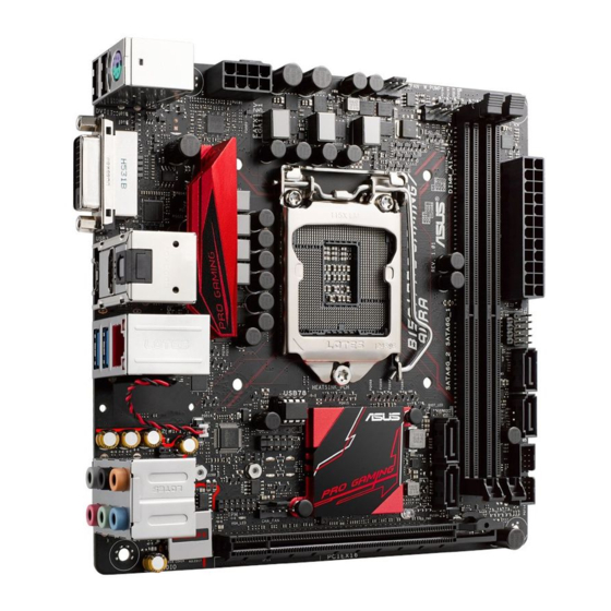
Motherboard Overview
2
Motherboard Layout
3
Connectors
4
Onboard Led
Download this manual
B150I PRO GAMING/
AURA SERIES
Table of
Contents
Previous
Page
Next
Page
1
2
3
4
5
Advertisement
Table of Contents
Need help?
Do you have a question about the B150I PRO GAMING and is the answer not in the manual?
Ask a question
Questions and answers
Related Manuals for Asus B150I PRO GAMING
Motherboard Asus B150I Pro Gaming/Aura Series Quick Start Manual
(2 pages)
Motherboard Asus B150 PRO GAMING D3 User Manual
(94 pages)
Motherboard Asus B150 PRO GAMING User Manual
(92 pages)
Motherboard Asus B150-A Technical Manual
Pin definition (18 pages)
Motherboard Asus B150-PRO User Manual
(54 pages)
Motherboard Asus B150M-A D3 Manual
(51 pages)
Motherboard Asus B150M-D D3 User Manual
(45 pages)
Motherboard Asus Trooper B150 D3 User Manual
(68 pages)
Motherboard Asus B150M-PLUS Instruction Manual
(51 pages)
Motherboard Asus B150-PLUS Manual
(53 pages)
Motherboard Asus B150-A User Manual
(27 pages)
Motherboard Asus B150-PLUS D3 User Manual
(56 pages)
Motherboard Asus B150M-C D3 Manual
(60 pages)
Motherboard Asus B150M-C User Manual
(60 pages)
Motherboard Asus B150M Pro Gaming User Manual
(92 pages)
Motherboard Asus B150M-C-D3 B150M-C-D3/CSM Manual
(60 pages)
This manual is also suitable for:
Aura series
Table of Contents
Print
Rename the bookmark
Delete bookmark?
Delete from my manuals?
Login
Sign In
OR
Sign in with Facebook
Sign in with Google
Upload manual
Upload from disk
Upload from URL


Need help?
Do you have a question about the B150I PRO GAMING and is the answer not in the manual?
Questions and answers