Table of Contents
Advertisement
Advertisement
Chapters
Table of Contents

Related Manuals for Asus B150-PLUS


Summary of Contents for Asus B150-PLUS
- Page 1 B150-PLUS...
- Page 2 Product warranty or service will not be extended if: (1) the product is repaired, modified or altered, unless such repair, modification of alteration is authorized in writing by ASUS; or (2) the serial number of the product is defaced or missing.
-
Page 3: Table Of Contents
Contents Safety information ..................iv About this guide ..................iv Package contents ..................vi B150-PLUS specifications summary ............vi Chapter 1: Product introduction Before you proceed ..............1-1 Motherboard overview ..............1-1 Central Processing Unit (CPU) ........... 1-3 System memory ................1-7 Expansion slots ................ -
Page 4: Safety Information
Safety information Electrical safety • To prevent electrical shock hazard, disconnect the power cable from the electrical outlet before relocating the system. • When adding or removing devices to or from the system, ensure that the power cables for the devices are unplugged before the signal cables are connected. If possible, disconnect all power cables from the existing system before you add a device. -
Page 5: Conventions Used In This Guide
Refer to the following sources for additional information and for product and software updates. ASUS websites The ASUS website provides updated information on ASUS hardware and software products. Refer to the ASUS contact information. Optional documentation Your product package may include optional documentation, such as warranty flyers, that may have been added by your dealer. -
Page 6: Package Contents
* Hyper DIMM support is subject to the physical characteristics of individual CPUs. Please refer to Memory QVL for details. ** Refer to www.asus.com for the Memory QVL (Qualified Vendors List). *** The maximum memory frequency varies per processor. Integrated Graphics Processor - Intel HD Graphics support ®... -
Page 7: Specifications
- ASUS Overvoltage Protection - World-class circuit-protection power design - ASUS DIGI +VRM - 6 Phase digital power design - ASUS DRAM Overcurrent Protection - Prevents damage from short circuit - ASUS Stainless Steel Back I/O - 3x corrosion-resistance for greater... - Page 8 ASUS Exclusive Features features - USB 3.0 Boost featuring USB 3.0 transmission - ASUS Ai Charger - ASUS AI Suite 3 EZ DIY Push Notice - Monitor your PC status with smart devices in real time UEFI BIOS EZ Mode...
- Page 9 128Mb Flash ROM, UEFI AMI BIOS, PnP, DMI 3.0, WfM2.0, SM BIOS 3.0, BIOS features ACPI 5.0, Multi-language BIOS, ASUS EZ Flash 3, CrashFree BIOS 3, F6 Qfan Control, F3 My Favorites, Quick Note, Last Modified log, F12 PrintScreen, and ASUS DRAM SPD (Serial Presence Detect) memory...
-
Page 11: Chapter 1: Product Introduction
Placement direction When installing the motherboard, place it into the chassis in the correct orientation. The edge with external ports goes to the rear part of the chassis as indicated in the image. 1.2.2 Screw holes Place six screws into the holes indicated by circles to secure the motherboard to the chassis. Do not overtighten the screws! Doing so can damage the motherboard. ASUS B150-PLUS... -
Page 12: Motherboard Layout
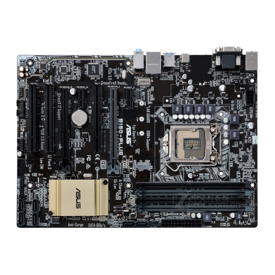
B150-PLUS Place this side towards the rear of the chassis 1.2.3 Motherboard layout 21.8cm(8.6in) KBMS_USB910 CPU_FAN DIGI EATX12V +VRM LGA1151 USB3_C3 USB3_56 LAN_USB78 AUDIO CHA_FAN1 PCIEX1_1 B150-PLUS PCIEX16_1 Realtek 8111GR PCI1 1083 Intel ® PCIEX1_2 BATTERY B150 PCIEX16_2 Super 128Mb... -
Page 13: Central Processing Unit (Cpu)
7. Clear RTC RAM (2-pin CLRTC) 1-12 8. System panel connector (20-5 pin PANEL) 1-19 9. USB 3.0 connector (20-1 pin USB3_12) 1-16 10. USB 2.0 connector (10-1 pin USB1112) 1-16 11. Serial port connector (10-1 pin COM) 1-15 12. Digital audio connector (4-1 pin SPDIF_OUT) 1-18 13. Front panel audio connector (10-1 pin AAFP) 1-18 Central Processing Unit (CPU) This motherboard comes with a surface mount LGA1151 socket designed for the 6th Generation Intel Core™ i7 / Core™ i5 / Core™ i3, Pentium and Celeron processors. ® ® ® B150-PLUS B150-PLUS CPU socket LGA1151 ASUS B150-PLUS... -
Page 14: Installing The Cpu
Unplug all power cables before installing the CPU. • Ensure that you install the correct CPU designed for the LGA1151 socket only. DO NOT install a CPU designed for LGA1150, LGA1155 and LGA1156 sockets on the LGA1151 socket. • Upon purchase of the motherboard, ensure that the PnP cap is on the socket and the socket contacts are not bent. Contact your retailer immediately if the PnP cap is missing, or if you see any damage to the PnP cap/socket contacts/motherboard components. • Keep the cap after installing the motherboard. ASUS will process Return Merchandise Authorization (RMA) requests only if the motherboard comes with the cap on the LGA1151 socket. • The product warranty does not cover damage to the socket contacts resulting from incorrect CPU installation/removal, or misplacement/loss/incorrect removal of the PnP cap. 1.3.1 Installing the CPU Chapter 1: Product introduction... -
Page 15: Cpu Heatsink And Fan Assembly Installation
1.3.2 CPU heatsink and fan assembly installation Apply the Thermal Interface Material to the CPU heatsink and CPU before you install the heatsink and fan if necessary. ASUS B150-PLUS... - Page 16 To install the CPU heatsink and fan assembly To uninstall the CPU heatsink and fan assembly Chapter 1: Product introduction...
-
Page 17: System Memory
System memory 1.4.1 Overview This motherboard comes with two Double Data Rate 4 (DDR4) Dual Inline Memory Module (DIMM) sockets. A DDR4 module is notched differently from a DDR, DDR2, or DDR3 module. DO NOT install a DDR, DDR2, or DDR3 memory module to the DDR4 slot. According to Intel CPU spec, DIMM voltage below 1.35 V is recommended to protect the ® CPU. B150-PLUS B150-PLUS 288-pin DDR4 DIMM sockets 1.4.2 Memory configurations You may install 2 GB, 4 GB, 8 GB, and 16 GB unbuffered non-ECC DDR4 DIMMs into the DIMM sockets. You can refer to the recommended memory population below. Recommended memory configurations ASUS B150-PLUS... -
Page 18: Installing A Dimm
I nstall a 64-bit Windows OS if you want to install 4GB or more on the ® motherboard. F or more details, refer to the Microsoft support site at http://support.microsoft. ® com/kb/929605/en-us. • The default memory operation frequency is dependent on its Serial Presence Detect (SPD), which is the standard way of accessing information from a memory module. Under the default state, some memory modules for overclocking may operate at a lower frequency than the vendor-marked value. To operate at the vendor-marked or at a higher frequency, refer to section 2.5 Ai Tweaker menu for manual memory frequency adjustment. • Always install the DIMMS with the same CAS Latency. For an optimum compatibility, we recommend that you install memory modules of the same version or data code (D/C) from the same vendor. Check with the vendor to get the correct memory modules. • Visit the ASUS website at www.asus.com for the latest QVL. 1.4.3 Installing a DIMM Chapter 1: Product introduction... - Page 19 To remove a DIMM ASUS B150-PLUS...
-
Page 20: Expansion Slots
Expansion slots In the future, you may need to install expansion cards. The following sub-sections describe the slots and the expansion cards that they support. Unplug the power cord before adding or removing expansion cards. Failure to do so may cause you physical injury and damage motherboard components. 1.5.1 Installing an expansion card To install an expansion card: Before installing the expansion card, read the documentation that came with it and make the necessary hardware settings for the card. Remove the system unit cover (if your motherboard is already installed in a chassis). -
Page 21: Pci Slots
– – PCI1 – – shared – PCI2 – – – shared PCI3 shared – – – 8111GR LAN Controller – – – shared HD Audio shared – – – SATA Controller shared – – – XHCI shared – – – ASUS B150-PLUS 1-11... -
Page 22: Headers
Headers Clear RTC RAM (2-pin CLRTC) This header allows you to clear the Real Time Clock (RTC) RAM in CMOS. You can clear the CMOS memory of date, time, and system setup parameters by erasing the CMOS RTC RAM data. The onboard button cell battery powers the RAM data in CMOS, which include system setup information such as system passwords. B150-PLUS CLRTC PIN 1 B150-PLUS Clear RTC RAM To erase the RTC RAM: Turn OFF the computer and unplug the power cord. Use a metal object such as a screwdriver to short the two pins. Plug the power cord and turn ON the computer. Hold down the <Del> key during the boot process and enter BIOS setup to re- enter data. • If the steps above do not help, remove the onboard battery and short the two pins again to clear the CMOS RTC RAM data. After clearing the CMOS, reinstall the battery. • You do not need to clear the RTC when the system hangs due to overclocking. For system failure due to overclocking, use the CPU Parameter Recall (C.P.R.) feature. Shut down and reboot the system, then the BIOS automatically resets parameter settings to default values. 1-12 Chapter 1: Product introduction... -
Page 23: Connectors
1Gbps connection (Blinking) LAN port Orange Ready to (Blinking then wake up from steady) S5 mode Line In port (light blue). This port connects to the tape, CD, DVD player, or other audio sources. Line Out port (lime). This port connects to a headphone or a speaker. In the 4.1, 5.1, and 7.1-channel configurations, the function of this port becomes Front Speaker Out. Microphone port (pink). This port connects to a microphone. Refer to the audio configuration table on the next page for the function of the audio ports in 2.1, 4.1, 5.1, or 7.1-channel configuration. ASUS B150-PLUS 1-13... - Page 24 Audio 2.1, 4.1, 5.1, or 7.1-channel configuration Headset Port 4.1-channel 5.1-channel 7.1-channel 2.1-channel Light Blue (Rear panel) Line In Rear Speaker Out Rear Speaker Out Rear Speaker Out Lime (Rear panel) Line Out Front Speaker Out Front Speaker Out Front Speaker Out Pink (Rear panel) Mic In Mic In Bass/Center Bass/Center Lime (Front panel) Side Speaker Out To configure a 7.1-channel audio output: Use a chassis with HD audio module in the front panel to support a 7.1-channel audio output. USB 2.0 ports. These 4-pin Universal Serial Bus (USB) ports are for USB 2.0/1.1 devices.
-
Page 25: Serial Port Connector (10-1 Pin Com)
Serial port connector (10-1 pin COM) This connector is for a serial (COM) port. Connect the serial port module cable to this connector, then install the module to a slot opening at the back of the system chassis. PIN 1 B150-PLUS B150-PLUS Serial port (COM) connector The COM module is purchased separately. CPU and chassis fan connectors (4-pin CPU_FAN, 4-pin CHA_FAN 1/2) Connect the fan cables to the fan connectors on the motherboard, ensuring that the black wire of each cable matches the ground pin of the connector... -
Page 26: Usb 3.0 Connector (20-1 Pin Usb3_12)
USB 3.0 connector (20-1 pin USB3_12) This connector allows you to connect a USB 3.0 module for additional USB 3.0 front or rear panel ports. With an installed USB 3.0 module, you can enjoy all the benefits of USB 3.0 including faster data transfer speeds of up to 5 Gbps, faster charging time for USB-chargeable devices, optimized power efficiency, and backward compatibility with USB 2.0. USB3_12 B150-PLUS PIN 1 B150-PLUS USB3.0 Front panel connector The USB 3.0 module is purchased separately. USB 2.0 connector (10-1 pin USB1112) This connector is for the USB 2.0 port. Connect the USB module cable to this connector, then install the module to a slot opening at the back of the system chassis. This USB connector complies with USB 2.0 specifications and supports up to 480Mbps connection speed. USB1112 B150-PLUS PIN 1 B150-PLUS USB2.0 connector Never connect a 1394 cable to the USB connector. Doing so will damage the motherboard! The USB 2.0 module is purchased separately. -
Page 27: Atx Power Connectors (24-Pin Eatxpwr, 8-Pin Eatx12V)
Power OK -5 Volts PIN 1 +5 Volts +5 Volts PSON# B150-PLUS +3 Volts -12 Volts +3 Volts +3 Volts PIN 1 B150-PLUS ATX power connectors • For a fully configured system, we recommend that you use a power supply unit (PSU) that complies with ATX 12 V Specification 2.0 (or later version) and provides a minimum power of 350 W. • DO NOT forget to connect the 4-pin/8-pin ATX +12V power plug. Otherwise, the system will not boot up. • We recommend that you use a PSU with higher power output when configuring a system with more power-consuming devices or when you intend to install additional devices. The system may become unstable or may not boot up if the power is inadequate. -
Page 28: Digital Audio Connector (4-1 Pin Spdif_Out)
Front panel audio connector (10-1 pin AAFP) This connector is for a chassis-mounted front panel audio I/O module that supports either HD Audio or legacy AC`97 audio standard. Connect one end of the front panel audio I/O module cable to this connector. AAFP B150-PLUS PIN 1 HD-audio-compliant Legacy AC’97 pin definition compliant definition B150-PLUS Front panel audio connector • We recommend that you connect a high-definition front panel audio module to this connector to avail of the motherboard’s high-definition audio capability. • If you want to connect a high-definition front panel audio module to this connector, set the Front Panel Type item in the BIOS setup to [HD]. If you want to connect an AC’97 front panel audio module to this connector, set the item to [AC97]. By default, this connector is set to [HD]. Digital audio connector (4-1 pin SPDIF_OUT) This connector is for an additional Sony/Philips Digital Interface (S/PDIF) port. Connect the S/PDIF Out module cable to this connector, then install the module to a slot opening at the back of the system chassis. -
Page 29: System Panel Connector (20-5 Pin Panel)
System panel connector (20-5 pin PANEL) This connector supports several chassis-mounted functions. PANEL +PWR_LED- SPEAKER PWR_SW PIN 1 B150-PLUS +HDD_LED- RESET +PWR_LED- * Requires an ATX power supply B150-PLUS System panel connector • System power LED (4-pin +PWR_LED-) This 4-pin connector is for the system power LED. Connect the chassis power LED cable to this connector. The system power LED lights up when you turn on the system power, and blinks when the system is in sleep mode. • Hard disk drive activity LED (2-pin +HDD_LED-) This 2-pin connector is for the HDD Activity LED. Connect the HDD Activity LED cable to this connector. The HDD LED lights up or flashes when data is read from or written to the HDD. • System warning speaker (4-pin SPEAKER) This 4-pin connector is for the chassis-mounted system warning speaker. The speaker allows you to hear system beeps and warnings. -
Page 30: M.2 Socket
RSATA_TXP1 RSATA_TXN1 RSATA_RXN1 RSATA_RXP1 B150-PLUS SATA6G_3 SATA6G_4 SATA6G_2 RSATA_TXP2 RSATA_TXN2 RSATA_RXN2 RSATA_RXP2 B150-PLUS Intel SATA 6.0Gb/s connectors ® When using hot-plug and NCQ, set the SATA Mode Selection item in the BIOS to [AHCI]. M.2 socket 3 This socket allows you to install an M.2 (NGFF) SSD module. M.2(SOCKET3) B150-PLUS B150-PLUS M.2(SOCKET3) This socket supports M Key and 2242/2260/2280 storage devices. The M.2 (NGFF) SSD module is purchased separately. 1-20 Chapter 1: Product introduction... -
Page 31: Software Support
To run the Support DVD Place the Support DVD into the optical drive. If Autorun is enabled in your computer, the DVD automatically displays the lists of the unique features of your ASUS motherboard. Click the Driver, Utilities, Manual, or Special tabs to display their respective menus. The following screen is for reference only. Click an icon to display a tab Click to install Tick an item and click Install to install it If Autorun is NOT enabled in your computer, browse the contents of the Support DVD to locate the file Setup.exe in the root folder. Double-click the Setup.exe to run the DVD. ASUS B150-PLUS 1-21... - Page 32 1-22 Chapter 1: Product introduction...
-
Page 33: Chapter 2: Bios Information
Managing and updating your BIOS Save a copy of the original motherboard BIOS file to a USB flash disk in case you need to restore the BIOS in the future. Copy the original motherboard BIOS using the ASUS Update utility. -
Page 34: Asus Ez Flash
2.1.2 ASUS EZ Flash 3 The ASUS EZ Flash 3 feature allows you to update the BIOS without using an OS‑based utility. • Ensure that you load the BIOS default settings to ensure system compatibility and stability. Select the Load Optimized Defaults item under the Exit menu. See section 2.10 Exit Menu for details. -
Page 35: Asus Crashfree Bios 3 Utility
2.1.3 ASUS CrashFree BIOS 3 utility The ASUS CrashFree BIOS 3 is an auto recovery tool that allows you to restore the BIOS file when it fails or gets corrupted during the updating process. You can restore a corrupted BIOS file using the motherboard support DVD or a USB flash drive that contains the updated BIOS file. - Page 36 ENTER to select boot device ESC to boot using defaults P2: ST3808110AS (76319MB) aigo miniking (250MB) UEFI: (FAT) ASUS DRW-2014L1T(4458MB) P1: ASUS DRW-2014L1T(4458MB) UEFI: (FAT) aigo miniking (250MB) Enter Setup When the booting message appears, press <Enter> within five (5) seconds to enter FreeDOS prompt.
- Page 37 DO NOT shut down or reset the system while updating the BIOS to prevent system boot failaure. Ensure to load the BIOS default settings to ensure system compatibility and stability. Select the Load Optimized Defaults item under the Exit BIOS menu. See section 2.10 Exit Menu for details. ASUS B150-PLUS 2‑5...
-
Page 38: Bios Setup Program
The BIOS setup screens shown in this section are for reference purposes only, and may not exactly match what you see on your screen. • Visit the ASUS website at www.asus.com to download the latest BIOS file for this motherboard. •... - Page 39 Click the button to manually menus tune the fans Shows the Selects the boot bootable devices Loads optimized device priority default settings The boot device options vary depending on the devices you installed to the system. ASUS B150-PLUS 2‑7...
-
Page 40: Advanced Mode
Advanced Mode The Advanced Mode provides advanced options for experienced end‑users to configure the BIOS settings. The figure below shows an example of the Advanced Mode. Refer to the following sections for the detailed configurations. To access the EZ Mode, click EzMode(F7) or press <F7>. Q-Fan control MyFavorite Quick Note... -
Page 41: Menu Bar
BIOS settings and save it to MyFavorites menu. Refer to section 2.3 My Favorites for more information. Q-Fan Control (F6) This button above the menu bar displays the current settings of your fans. Use this button to manually tweak the fans to your desired settings. ASUS B150-PLUS... -
Page 42: Hot Keys
Search on FAQ Move your mouse over this button to show a QR code. Scan this QR code with your mobile device to connect to the ASUS BIOS FAQ web page. You can also scan the QR code below. Quick Note (F9) This button above the menu bar allows you to key in notes of the activities that you have done in BIOS. -
Page 43: My Favorites
Press <F3> on your keyboard or click from the BIOS screen to open Setup Tree Map screen. On the Setup Tree Map screen, select the BIOS items that you want to save in MyFavorites screen. Selected shortcut items Main menu panel Submenu panel ASUS B150-PLUS 2-11... -
Page 44: Main Menu
Select an item from main menu panel, then click the submenu that you want to save as favorite from the submenu panel and click You cannot add the following items to My Favorite items: • User‑managed items such as language and boot order Click Exit (ESC) or press <esc>... -
Page 45: Ai Tweaker Menu
Be cautious when changing the settings of the Ai Tweaker menu items. Incorrect field values can cause the system to malfunction. The configuration options for this section vary depending on the CPU and DIMM model you installed on the motherboard. Scroll down to display other BIOS items. ASUS B150-PLUS 2‑13... -
Page 46: Advanced Menu
Advanced menu The Advanced menu items allow you to change the settings for the CPU and other system devices. Be cautious when changing the settings of the Advanced menu items. Incorrect field values can cause the system to malfunction. 2-14 Chapter 2: Getting started... -
Page 47: Monitor Menu
The Monitor menu displays the system temperature/power status, and allows you to change the fan settings. Scroll down to display the other BIOS items. Boot menu The Boot menu items allow you to change the system boot options. Scroll down to display the other BIOS items. ASUS B150-PLUS 2‑15... -
Page 48: Tool Menu
Tool menu The Tool menu items allow you to configure options for special functions. Select an item then press <Enter> to display the submenu. 2.10 Exit menu The Exit menu items allow you to load the optimal default values for the BIOS items, and save or discard your changes to the BIOS items. -
Page 49: Appendices
Cet appareil est conforme aux normes CNR exemptes de licence d’Industrie Canada. Le fonctionnement est soumis aux deux conditions suivantes : (1) cet appareil ne doit pas provoquer d’interférences et (2) cet appareil doit accepter toute interférence, y compris celles susceptibles de provoquer un fonctionnement non souhaité de l’appareil. ASUS B150-PLUS... -
Page 50: Canadian Department Of Communications Statement
ASUS Recycling/Takeback Services ASUS recycling and takeback programs come from our commitment to the highest standards for protecting our environment. We believe in providing solutions for you to be able to responsibly recycle our products, batteries, other components as well as the packaging materials. - Page 51 CE. das Diretivas da CE. Para mais detalhes, consulte a Declaração de Компания ASUS заявляет, что это устройство соответствует основным Conformidade CE. требованиям и другим соответствующим условиям европейских директив. Подробную информацию, пожалуйста, смотрите в декларации...
-
Page 52: Asus Contact Information
+1-510-739-3777 +1-510-608-4555 Web site http://www.asus.com/us/ Technical Support Support fax +1-812-284-0883 General support +1-812-282-2787 Online support http://www.service.asus.com/ ASUS COMPUTER GmbH (Germany and Austria) Address Harkort Str. 21-23, D-40880 Ratingen, Germany +49-2102-959931 Web site http://www.asus.com/de Online contact http://eu-rma.asus.com/sales Technical Support Telephone +49-2102-5789555... - Page 53 ASUS B150-PLUS...
Need help?
Do you have a question about the B150-PLUS and is the answer not in the manual?
Questions and answers