Table of Contents
Advertisement
Advertisement
Table of Contents

Related Manuals for Asus B150M Pro Gaming


Summary of Contents for Asus B150M Pro Gaming
- Page 1 B150M PRO GAMING...
- Page 2 Product warranty or service will not be extended if: (1) the product is repaired, modified or altered, unless such repair, modification of alteration is authorized in writing by ASUS; or (2) the serial number of the product is defaced or missing.
-
Page 3: Table Of Contents
Contents Safety information ..................iv About this guide ..................iv Package contents ..................vi B150M PRO GAMING specifications summary ........vi Chapter 1: Product Introduction Before you proceed ..............1-1 Motherboard overview ..............1-1 Central Processing Unit (CPU) ........... 1-5 System memory ................ -
Page 4: Safety Information
Safety information Electrical safety • To prevent electrical shock hazard, disconnect the power cable from the electrical outlet before relocating the system. • When adding or removing devices to or from the system, ensure that the power cables for the devices are unplugged before the signal cables are connected. If possible, disconnect all power cables from the existing system before you add a device. -
Page 5: Conventions Used In This Guide
Refer to the following sources for additional information and for product and software updates. ASUS websites The ASUS website provides updated information on ASUS hardware and software products. Refer to the ASUS contact information. Optional documentation Your product package may include optional documentation, such as warranty flyers that may have been added by your dealer. -
Page 6: Package Contents
Hyper DIMM support is subject to the physical characteristics of individual CPUs. Please refer to Memory QVL (Qualified Vendors List) for details. Refer to www.asus.com for the Memory QVL (Qualified Vendors List). Due to Intel chipset limitation, DDR4 2133 MHz and higher memory modules on XMP mode will run at the maximum transfer rate of DDR4 2133 MHz. - Page 7 ® Anti-surge LANGuard Intel B150 Chipset - supports ASUS USB 3.0 Boost ® - 6 x USB 3.0/2.0 ports (2 ports at mid-board; 4 ports at back panel, blue) - 6 x USB 2.0/1.1 ports (2 ports at mid-board; 4 ports at back panel) Gamer’s Guardian...
- Page 8 1 x 8-pin EATX 12V power connector 128 Mb Flash ROM, UEFI AMI BIOS, PnP, DMI 3.0, WfM 2.0, SM BIOS 3.0, ACPI 5.0, Multi-language BIOS, ASUS EZ Flash 3, CrashFree BIOS 3, F6 Q-fan BIOS features Control, F3 My Favorites, F9 Quick Note, Last Modified Log, F12 PrintScreen function, and ASUS DRAM SPD (Serial Presence Detect) memory information WfM 2.0, DMI 3.0, WOL by PME, PXE...
-
Page 9: Chapter 1: Product Introduction
1.2.1 Placement direction When installing the motherboard, place it into the chassis in the correct orientation. The edge with external ports goes to the rear part of the chassis as indicated in the image below. ASUS B150M PRO GAMING... -
Page 10: Screw Holes
1.2.2 Screw holes Place six (6) screws into the holes indicated by circles to secure the motherboard to the chassis. Do not overtighten the screws! Doing so can damage the motherboard. Place this side towards the rear of the chassis Chapter 1: Product Introduction... -
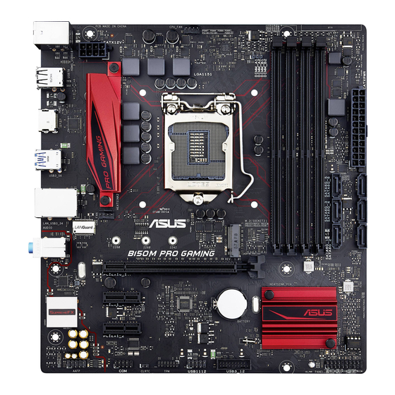
Page 11: Motherboard Layout
1.2.3 Motherboard layout ASUS B150M PRO GAMING... -
Page 12: Layout Contents
1.2.4 Layout contents Connectors/Jumpers/Slots/LED Page 1. ATX power connectors (24-pin EATXPWR, 8-pin EATX12V) 1-20 2. Intel LGA1151 CPU socket ® 3. CPU and chassis fan connectors (4-pin CPU_FAN, 4-pin CHA_FAN) 1-19 4. DDR4 DIMM slots 5. Intel B150 Serial ATA 6.0 Gb/s connectors (7-pin SATA6G_1-6) 1-23 ®... -
Page 13: Central Processing Unit (Cpu)
PnP cap/socket contacts/motherboard components. • Keep the cap after installing the motherboard. ASUS will process Return Merchandise Authorization (RMA) requests only if the motherboard comes with the cap on the LGA1151 socket. -
Page 14: Installing The Cpu
1.3.1 Installing the CPU Chapter 1: Product Introduction... -
Page 15: Cpu Heatsink And Fan Assembly Installation
1.3.2 CPU heatsink and fan assembly installation Apply the Thermal Interface Material to the CPU heatsink and CPU before you install the heatsink and fan if necessary. To install the CPU heatsink and fan assembly ASUS B150M PRO GAMING... -
Page 16: System Memory
To uninstall the CPU heatsink and fan assembly System memory 1.4.1 Overview This motherboard comes with four Double Data Rate 4 (DDR4) Dual Inline Memory Module (DIMM) sockets. A DDR4 module is notched differently from a DDR, DDR2, or DDR3 module. DO NOT install a DDR, DDR2, or DDR3 memory module to the DDR4 slot. -
Page 17: Memory Configurations
(D/C) from the same vendor. Check with the vendor to get the correct memory modules. • For system stability, use a more efficient memory cooling system to support a full memory load (4 DIMMs) or overclocking condition. • Visit the ASUS website at www.asus.com for the latest QVL. ASUS B150M PRO GAMING... -
Page 18: Dimm Installation
1.4.3 DIMM installation To remove a DIMM Chapter 1: Product Introduction 1-10... -
Page 19: Expansion Slots
When using PCI cards on shared slots, ensure that the drivers support “Share IRQ” or that the cards do not need IRQ assignments. Otherwise, conflicts will arise between the two PCI groups, making the system unstable and the card inoperable. ASUS B150M PRO GAMING 1-11... - Page 20 1.5.3 PCI Express 3.0 x1 slots This motherboard supports PCI Express x1 network cards, SCSI cards, and other cards that comply with the PCI Express specifications. 1.5.4 PCI Express 3.0 x16 slot This motherboard supports PCI Express x16 graphic cards that comply with the PCI Express specifications.
-
Page 21: Jumpers
You do not need to clear the RTC when the system hangs due to overclocking. For system failure due to overclocking, use the CPU Parameter Recall (C.P.R.) feature. Shut down and reboot the system, then the BIOS automatically resets parameter settings to default values. ASUS B150M PRO GAMING 1-13... -
Page 22: Connectors
Connectors 1.7.1 Rear panel connectors PS/2 keyboard/mouse combo port: This port is for a PS/2 mouse or keyboard. LAN (RJ-45) port: This port allows Gigabit connection to a Local Area Network (LAN) through a network hub. LAN port LED indications Activity Link LED Speed LED Status... - Page 23 Rear Speaker Out Rear Speaker Out Rear Speaker Out Lime Line Out Front Speaker Out Front Speaker Out Front Speaker Out Pink Mic In Mic In Bass/Center Bass/Center Lime (Front Panel) – – – Side Speaker Out ASUS B150M PRO GAMING 1-15...
-
Page 24: Internal Connectors
1.7.2 Internal connectors Serial port connector (10-1 pin COM) This connector is for a serial (COM) port. Connect the serial port module cable to this connector, and then install the module to a slot opening at the back of the system chassis. - Page 25 USB connector complies with USB 2.0 specifications and supports up to 480Mbps connection speed. Never connect a 1394 cable to the USB connectors. Doing so will damage the motherboard! The USB 2.0 module is purchased separately. ASUS B150M PRO GAMING 1-17...
- Page 26 USB 3.0 connector (20-1 pin USB3_12) This connector allows you to connect a USB 3.0 module for additional USB 3.0 front or rear panel ports. With an installed USB 3.0 module, you can enjoy all the benefits of USB 3.0 including faster data transfer speeds of up to 5Gbps, faster charging time for USB-chargeable devices, optimized power efficiency, and backward compatibility with USB 2.0.
- Page 27 • The CPU_FAN connector supports a CPU fan of maximum 1A (12W) fan power. • The CPU_FAN connector and CHA_FAN connector support the ASUS FAN Xpert feature. • The CPU fan connector detects the type of CPU fan installed and automatically switches the control modes.
- Page 28 ATX power connectors (24-pin EATXPWR, 8-pin EATX12V) These connectors are for ATX power supply plugs. The power supply plugs are designed to fit these connectors in only one orientation. Find the proper orientation and push down firmly until the connectors completely fit. •...
- Page 29 If you want to connect a high-definition front panel audio module to this connector, set the Front Panel Type item in the BIOS setup to [HD Audio]. By default, this connector is set to [HD Audio]. See section 2.6.7 Onboard Devices Configuration for details. ASUS B150M PRO GAMING 1-21...
- Page 30 TPM connector (14-1 pin TPM) This connector supports a Trusted Platform Module (TPM) system, which securely stores keys, digital certificates, passwords and data. A TPM system also helps enhance the network security, protects digital identities, and ensures platform integrity. Chapter 1: Product Introduction 1-22...
- Page 31 These connectors connect to Serial ATA 6.0 Gb/s hard disk drives via Serial ATA 6.0 Gb/s signal cables. When the M.2 Socket 3 is operating in SATA mode, SATA port 1 will be disabled. To use SATA port 1, please set in the BIOS. ASUS B150M PRO GAMING 1-23...
-
Page 32: System Panel Connector
System panel connector (20-5 pin PANEL) This connector supports several chassis-mounted functions. • System power LED (4-pin +PWR_LED-) This 4-pin connector is for the system power LED. Connect the chassis power LED cable to this connector. The system power LED lights up when you turn on the system power, and blinks when the system is in sleep mode. -
Page 33: Onboard Led
ON, in sleep mode, or in soft-off mode. This is a reminder that you should shut down the system and unplug the power cable before removing or plugging in any motherboard component. The illustration below shows the location of the onboard LED. ASUS B150M PRO GAMING 1-25... - Page 34 SupremeFX LED The SupremeFX LED lights up in two ways to bring you an ultimate lighting effect. This LED also outlines the separation of the audio components from the rest of your motherboard. Lit mode Description Breathing mode The LED blinks intermittently. Still mode The LED becomes solid red.
-
Page 35: Software Support
Place the Support DVD into the optical drive. If Autorun is enabled in your computer, the DVD automatically displays the lists of the unique features of your ASUS motherboard. Click the Driver, Utilities, Manual, or Special tabs to display their respective menus. - Page 36 Chapter 1: Product Introduction 1-28...
-
Page 37: Chapter 2: Bios Setup
Managing and updating your BIOS Save a copy of the original motherboard BIOS file to a USB flash disk in case you need to restore the BIOS in the future. Copy the original motherboard BIOS using the ASUS Update utility. -
Page 38: Asus Ez Flash
2.1.2 ASUS EZ Flash 3 The ASUS EZ Flash 3 feature allows you to update the BIOS without using an OS‑based utility. • Load the BIOS default settings to ensure system compatibility and stability. Select the Load Optimized Defaults item under the Exit menu. See section 2.10 Exit Menu for details. -
Page 39: Asus Crashfree Bios 3 Utility
2.1.3 ASUS CrashFree BIOS 3 utility The ASUS CrashFree BIOS 3 is an auto recovery tool that allows you to restore the BIOS file when it fails or gets corrupted during the updating process. You can restore a corrupted BIOS file using the motherboard support DVD or a USB flash drive that contains the updated BIOS file. - Page 40 ENTER to select boot device ESC to boot using defaults P2: ST3808110AS (76319MB) aigo miniking (250MB) UEFI: (FAT) ASUS DRW-2014L1T(4458MB) P1: ASUS DRW-2014L1T(4458MB) UEFI: (FAT) aigo miniking (250MB) Enter Setup When the booting message appears, press <Enter> within five (5) seconds to enter FreeDOS prompt.
- Page 41 DO NOT shut down or reset the system while updating the BIOS to prevent system boot failure. Ensure to load the BIOS default settings to ensure system compatibility and stability. Select the Load Optimized Defaults item under the Exit BIOS menu. See section 2.10 Exit Menu for details. ASUS B150M PRO GAMING 2‑5...
-
Page 42: Bios Setup Program
The BIOS setup screens shown in this section are for reference purposes only, and may not exactly match what you see on your screen. • Visit the ASUS website at www.asus.com to download the latest BIOS file for this motherboard. •... - Page 43 Search on FAQs manually tune the fans Saves the changes and resets the system Selects the boot Loads optimized device priority default settings The boot device options vary depending on the devices you installed to the system. ASUS B150M PRO GAMING 2‑7...
-
Page 44: Advanced Mode
2.2.2 Advanced Mode The Advanced Mode provides advanced options for experienced end‑users to configure the BIOS settings. The figure below shows an example of the Advanced Mode. Refer to the following sections for the detailed configurations. To access the EZ Mode, click EzMode(F7) or press <F7>. Quick Note MyFavorite Qfan control... -
Page 45: Menu Items
This button above the menu bar allows you to key in notes of the activities that you have done in BIOS. • The Quick Note function does not support the following keyboard functions: delete, cut, copy and paste. • You can only use the alphanumeric characters to enter your notes. ASUS B150M PRO GAMING... -
Page 46: Hot Keys
Search on FAQ Move your mouse over this button to show a QR code. Scan this QR code with your mobile device to connect to the ASUS BIOS FAQ web page. You can also scan the QR code below. Scroll bar A scroll bar appears on the right side of a menu screen when there are items that do not fit on the screen. -
Page 47: Qfan Control
Click to activate DC Mode Click to activate configured PWM Mode Click to apply the Select a profile to fan setting apply to your fans Click to undo Click to go back the changes to main menu ASUS B150M PRO GAMING 2-11... - Page 48 Configuring fans manually Select Manual from the list of profiles to manually configure your fans’ operating speed. Click to manually configure Speed points your fans To configure your fans: Select the fan that you want to configure and to view its current status. Click and drag the speed points to adjust the fans’...
-
Page 49: My Favorites
Press <F3> on your keyboard or click from the BIOS screen to open Setup Tree Map screen. On the Setup Tree Map screen, select the BIOS items that you want to save in MyFavorites screen. ASUS B150M PRO GAMING 2‑13... - Page 50 Main menu panel Selected shortcut items Submenu panel Select an item from main menu panel, and then click the submenu that you want to save as favorite from the submenu panel and click You cannot add the following items to My Favorite items: •...
-
Page 51: Main Menu
RAM to clear the BIOS password. See section 1.6 Jumpers for information on how to erase the RTC RAM. • The Administrator Password and User Password items on the screen show the default Not Installed. After you set a password, these items show Installed. ASUS B150M PRO GAMING 2‑15... -
Page 52: Administrator Password
Administrator Password If you have set an administrator password, we recommend that you enter the administrator password for accessing the system. To set an administrator password: Select the Administrator Password item and press <Enter>. From the Create New Password box, key in a password, and then press <Enter>. From the Confirm New Password box, key in your password again to confirm the password, and then click OK. -
Page 53: Ai Tweaker Menu
This item allows you to set the CPU core ratio limit per core or synchronize automatically to all cores. Configuration options: [Auto] [Sync All Cores] [Per Core] When the CPU Core Ratio is set to [Sync All Cores] or [Per Core], the following items appear. ASUS B150M PRO GAMING 2‑17... - Page 54 1-Core Ratio Limit [Auto] Configure the 1‑core ratio limit that must be higher than or equal to the 2‑core ratio limit. 2-Core Ratio Limit [Auto] Configure the 2‑core ratio limit that must be higher than or equal to the 3‑core ratio limit. The 1‑core ratio limit must not be set to [Auto].
-
Page 55: Dram Timing Control
2.5.5 EPU Power Saving Mode [Disabled] The ASUS EPU (Energy Processing Unit) applies settings for minimum system power consumption. Enable this item to apply lower CPU Core/Cache Voltage and help save energy consumption. Configuration options: [Disabled] [Enabled] 2.5.6 CPU SVID Support [Auto] Disable this item to prevent the CPU from communicating with the external voltage regulator. - Page 56 CPU VRM Switching Frequency [Auto] This item affects the VRM transient response and VRM component temperatures. Setting a higher switching frequency will result in better transient response at the expense of higher VRM temperature. Configuration options: [Auto] [Manual] DO NOT remove the thermal module. The thermal conditions should be monitored. The following item appears only when the CPU VRM Switching Frequency is set to [Manual].
- Page 57 IA DC Load Line [Auto] This item allows you to set the DC loadline defined in 1/100 mOhms. Use the <+> and <‑> keys to adjust the value. The values range from 0 mOhms to 62.49 mOhms. ASUS B150M PRO GAMING 2-21...
- Page 58 2.5.10 CPU Core/Cache Current Limit Max. [Auto] Allows you to set a higher current limit to prevent a frequency or power throttling when overclocking. Use the <+> or <‑> keys to adjust the value. The values range from 0.00A to 255.50A with a 0.25A interval.
- Page 59 DRAM DATA REF Voltage on CHB DIMM1 Rank0 BL0-7 [Auto] Configures the DRAM Data REF Voltage. Configuration options: [Auto] [0] ‑ [63] DRAM DATA REF Voltage on CHB DIMM1 Rank1 BL0-7 [Auto] Configures the DRAM Data REF Voltage. Configuration options: [Auto] [0] ‑ [63] ASUS B150M PRO GAMING 2‑23...
-
Page 60: Advanced Menu
Advanced menu The Advanced menu items allow you to change the settings for the CPU and other system devices. Be cautious when changing the settings of the Advanced menu items. Incorrect field values can cause the system to malfunction. 2.6.1 CPU Configuration The items in this menu show the CPU‑related information that the BIOS automatically detects. -
Page 61: Cpu Power Management Configuration
This item allows you to set the Package C State limit. Configuration options: [C0/C1] [C2] [C3] [C6] [C7] [C7s] [C8] [Auto] CFG lock [Disabled] This item allows you to enable or disable the CFG lock. Configuration options: [Disabled] [Enabled] ASUS B150M PRO GAMING 2‑25... -
Page 62: Platform Misc Configuration
2.6.2 Platform Misc Configuration The items in this menu allow you to configure the platform‑related features. PCI Express Native Power Management [Disabled] This item allows you to enhance the power saving feature of PCI Express and perform ASPM operations in the operating system. Configuration options: [Disabled] [Enabled] The following items appear only when you set the PCI Express Native Power Management to [Enabled]. -
Page 63: Graphics Configuration
Configuration options: [Enabled] [Disabled] 2.6.4 PCH Configuration This item allows you to configure the PCH parameters. PCI Express Configuration PCIe Speed [Auto] Allows you to configure the PCI Express port speed. Configuration options: [Auto] [Gen1] [Gen2] [Gen3] ASUS B150M PRO GAMING 2‑27... -
Page 64: Pch Storage Configuration
SATA port items show Empty if no SATA device is installed to the corresponding SATA port. Hyper Kit Mode [Disabled] Disables this option for M.2 devices. Enables this option for ASUS Hyper kit card. Configuration options: [Disabled] [Enabled] SATA Controller(s) [Enabled] Enables or disables the onboard SATA device. -
Page 65: Usb Configuration
[HD Audio] Sets the front panel audio connector (AAFP) mode to high definition audio. [AC97] Sets the front panel audio connector (AAFP) mode to legacy AC’97. ASUS B150M PRO GAMING 2-29... -
Page 66: Serial Port Configuration
Audio LED Lighting [Breathing Mode] Allows you to set the behavior of the audio LED. Configuration options: [Disabled] [Still Mode] [Breathing Mode] M.2/SATA6G_1 Configuration [Auto] Configuration options: [Auto] [Manual] The following item appears only when you set the M.2/SATA6G_1 Configuration to [Manual]. -
Page 67: Apm Configuration
Ipv4/Ipv6 PXE Support [Enabled] This item allows you to enable or disable the Ipv4/Ipv6 PXE Boot Support. Configuration options: [Disabled] [Enabled] 2.6.10 HDD/SSD SMART Information This menu displays the SMART information of the connected devices. ASUS B150M PRO GAMING 2‑31... -
Page 68: Monitor Menu
Monitor menu The Monitor menu displays the system temperature/power status, and allows you to change the fan settings. Scroll down to display the other BIOS items. 2.7.1 CPU/MotherBoard Temperature [xxx°C/xxx°F] The onboard hardware monitor automatically detects and displays the CPU and motherboard temperatures. - Page 69 Use the <+> and <‑> keys to adjust the minimum CPU fan duty cycle. The values range from 60% to 100%. The CPU fan will operate at the minimum duty cycle when the CPU temperature is lower than the CPU lower temperature. ASUS B150M PRO GAMING 2‑33...
- Page 70 Chassis Fan Q-Fan Control [DC Mode] [Disabled] Disables the chassis Q‑Fan control. [DC mode] Enables the chassis Q‑Fan control in DC mode for 3‑pin chassis fan. [PWM mode] Enables the chassis Q‑Fan control in PWM mode for 4‑pin chassis fan. The following items appear only when you set the Chassis Fan Q-Fan Control to [PWM Mode] or [DC Mode].
- Page 71 This item allows the fan to run at 0% duty cycle when the temperature of the source is dropped below the lower temperature. Configuration options: [Disabled] [Enabled] 2.7.5 Anti Surge Support [On] This item allows you to enable or disable the Anti Surge function. Configuration options: [On] [Off] ASUS B150M PRO GAMING 2‑35...
-
Page 72: Boot Menu
Boot menu The Boot menu items allow you to change the system boot options. Scroll down to display the other BIOS items. 2.8.1 Fast Boot [Enabled] [Disabled] Select to return to normal boot speed. [Enabled] Select to accelerate the boot speed. Next Boot after AC Power Loss [Normal Boot] [Normal Boot] Returns to normal boot on the next boot after an AC power loss. - Page 73 Option ROM Messages [Force BIOS] [Force BIOS] The third‑party ROM messages will be displayed during POST. [Keep Current] Disables the ROM messages and displays only the ASUS logo during POST. 2.8.6 Interrupt 19 Capture [Disabled] Enable this item to allow the option ROMs to trap the interrupt 19.
-
Page 74: Secure Boot
2.8.9 Secure Boot Allows you to configure the Windows secure boot settings and manage the secure boot keys. OS Type [Windows UEFI mode] Allows you to select your installed operating system. [Windows UEFI mode] This item allows you to execute the Microsoft secure boot check. -
Page 75: Boot Option Priorities
8 not ® ® supported). • To select the boot device during system startup, press <F8> when ASUS Logo appears. 2.8.11 Boot Override These items display the available devices. The number of device items that appears on the screen depends on the number of devices installed in the system. Click an item to start booting from the selected device. -
Page 76: Tool Menu
<Enter> to display the sub‑menu. 2.9.1 ASUS EZ Flash 3 Utility Allows you to run ASUS EZ Flash 3. Press <Enter> to launch the ASUS EZ Flash 3 screen. For more details, see section 2.1.2 ASUS EZ Flash 3. 2.9.2 Secure Erase SSD speed performance may degrade over time due to accumulated files and frequent data‑... -
Page 77: Asus Spd Information
Locked: SSDs might be locked if the Secure Erase process is either incomplete or being stopped. This may be due to a third party software that uses a different password defined by ASUS. You have to unlock the SSD in the software before proceeding with Secure Erase. -
Page 78: Exit Menu
2.10 Exit menu The Exit menu items allow you to load the optimal default values for the BIOS items, and save or discard your changes to the BIOS items. Load Optimized Defaults This option allows you to restore or load default values for all the setup options. When you select this option or if you press <F5>, a confirmation window appears. -
Page 79: Installing An Operating System
Connect the USB ODD or USB storage device to your 100 series platform. Insert the ASUS support DVD into a SATA ODD on your 100 series platform. Power on your system and press F8 during POST (Power‑On Self Test) to enter the boot screen. - Page 80 Select the USB ODD or USB storage device as the boot device. The USB 3.0 driver will be loaded automatically during installation startup. The “Setup is starting...” screen will show up if the USB 3.0 driver is loaded correctly. Follow the onscreen instructions to complete the Windows 7 installation.
- Page 81 ® source using a third‑party ISO software. Copy both “Auto_Unattend.xml” and “Auto_Unattend” folder from the root directory of the ASUS supporting DVD to your system. Edit the ISO file and add both “Auto_Unattend.xml” and “Auto_Unattend” folder into the ISO file.
- Page 82 • 1 x USB storage device (8GB or more) Insert the Windows 7 installation DVD. ® Launch the ASUS EZ Installer located on the ASUS support DVD. Select a method of creating a modified Windows 7 installation file: ® Windows 7 OS disk to USB storage device ®...
- Page 83 ‑ Click Yes to clear the contents on the USB storage device and create a bootable USB device. Make sure to backup contents on the USB storage device as it will be formatted. ‑ Once completed, click OK to finish. ASUS B150M PRO GAMING 2‑47...
- Page 84 Windows 7 OS disk to ISO file ® - Select Windows 7 OS disk to ISO file and then click Next. ‑ Check I agree and then click Next. ‑ Select the source of the Windows 7 installation disk and then click Next. ®...
- Page 85 The USB 3.0 driver will be loaded automatically during installation startup. The “Setup is starting...” screen will show up if the USB 3.0 driver is loaded correctly. Follow the onscreen instructions to complete the Windows 7 installation. ® ASUS B150M PRO GAMING 2-49...
- Page 86 Chapter 2: BIOS Setup 2‑50...
-
Page 87: Appendices
Consult the dealer or an experienced radio/TV technician for help. The use of shielded cables for connection of the monitor to the graphics card is required to assure compliance with FCC regulations. Changes or modifications to this unit not expressly approved by the party responsible for compliance could void the user’s authority to operate this equipment. ASUS B150M PRO GAMING... -
Page 88: Canadian Department Of Communications Statement
IC: Canadian Compliance Statement Complies with the Canadian ICES-003 Class B specifications. This device complies with RSS 210 of Industry Canada. This Class B device meets all the requirements of the Canadian interference-causing equipment regulations. This device complies with Industry Canada license exempt RSS standard(s). Operation is subject to the following two conditions: (1) this device may not cause interference, and (2) this device must accept any interference, including interference that may cause undesired operation of the device. - Page 89 ASUS Recycling/Takeback Services ASUS recycling and takeback programs come from our commitment to the highest standards for protecting our environment. We believe in providing solutions for you to be able to responsibly recycle our products, batteries, other components as well as the packaging materials.
- Page 90 CE. Za več informacij glejte Izjavo CE o skladnosti. Русский Компания ASUS заявляет, что это устройство соответствует основным требованиям и другим соответствующим условиям Español Por la presente, AsusTek Inc. declara que este dispositivo cumple европейских...
-
Page 91: Asus Contact Information
+1-510-739-3777 +1-510-608-4555 Web site http://www.asus.com/us/ Technical Support Support fax +1-812-284-0883 Telephone +1-812-282-2787 Online support http://qr.asus.com/techserv ASUS COMPUTER GmbH (Germany and Austria) Address Harkort Str. 21-23, D-40880 Ratingen, Germany +49-2102-959911 Web site http://www.asus.com/de Online contact http://eu-rma.asus.com/sales Technical Support Telephone +49-1805-010923 Support Fax... - Page 92 Appendices...
Need help?
Do you have a question about the B150M Pro Gaming and is the answer not in the manual?
Questions and answers