Table of Contents
Advertisement
Quick Links
®
Advanced Test Equipment Rentals
www.atecorp.com 800-404-ATEC (2832)
®
39/41B
Power Meter & Power Harmonics Analyzer
Service Manual
PN 601044
October 1995, Rev.1,9/00
© 1995,2000 Fluke Corporation, Inc. All rights reserved. Printed in U.S.A.
All product names are trademarks of their respective companies.
Advertisement
Table of Contents
Troubleshooting

Related Manuals for Fluke 39


Summary of Contents for Fluke 39
-
Page 1: Service Manual
Advanced Test Equipment Rentals www.atecorp.com 800-404-ATEC (2832) ® 39/41B Power Meter & Power Harmonics Analyzer Service Manual PN 601044 October 1995, Rev.1,9/00 © 1995,2000 Fluke Corporation, Inc. All rights reserved. Printed in U.S.A. All product names are trademarks of their respective companies. - Page 2 Fluke authorized resellers shall extend this warranty on new and unused products to end-user customers only but have no authority to extend a greater or different warranty on behalf of Fluke. Warranty support is available only if product is purchased through a Fluke authorized sales outlet or Buyer has paid the applicable international price.
-
Page 3: Table Of Contents
Table of Contents Chapter Title Page Introduction and Specifications............1-1 1-1. Introduction ..................1-3 1-2. Organization of the Service Manual............. 1-3 1-3. Conventions..................1-4 1-4. General Information ................1-4 1-5. Description ..................1-4 1-6. Power Requirements ................ 1-4 1-7. Options, Accessories and Related Equipment........1-4 1-8. - Page 4 39/41B Service Manual 2-23. Level Shifter ................2-9 2-24. A/D Converters ................2-9 2-25. Digital Kernel................... 2-10 2-26. Digital Signal Processor (U2) ............2-10 2-27. Programmable Logic Device ............2-10 2-34. SRAMs (U5,U6,U7) ..............2-13 2-35. EPROM (U4) ................2-13 2-36.
- Page 5 Contents (continued) Troubleshooting................. 5-1 5-1. Introduction ..................5-3 5-2. General Troubleshooting ..............5-3 5-3. Starting with a Dead Tester (Model 41B Only) ....... 5-3 5-4. Troubleshooting the Power Supply ............5-5 5-5. Troubleshooting the Digital Section............. 5-5 5-6. Troubleshooting the Digital Kernel ..........5-6 5-7.
- Page 6 39/41B Service Manual...
-
Page 7: List Of Tables
5-2. Power Supplies ...................... 5-5 5-3. Latch Signals for Voltage Ranges................5-10 6-1. Fluke 39 Final Assembly ..................6-5 6-2. Fluke 39 A1 Main PCA ..................6-7 6-3. Fluke 41B Final Assembly..................6-13 6-4. Fluke 41B A1 Main PCA..................6-16... - Page 8 39/41B Service Manual...
-
Page 9: List Of Figures
Battery Spring Adjustment ..................4-14 4-4. Calibration Access Hole ..................4-15 5-1. Test Point Locator....................5-4 6-1. Fluke 39 Final Assembly ..................6-6 6-2. Fluke 39 A1 Main PCA ..................6-11 6-3. Fluke 41B Final Assembly..................6-15 6-4. Fluke 41B A1 Main PCA..................6-20... - Page 10 39/41B Service Manual viii...
-
Page 11: Title Page
Chapter 1 Introduction and Specifications Title Page 1-1. Introduction .................... 1-3 1-2. Organization of the Service Manual ............1-3 1-3. Conventions.................... 1-4 1-4. General Information ................1-4 1-5. Description..................1-4 1-6. Power Requirements ................1-4 1-7. Options, Accessories and Related Equipment ........1-4 1-8. - Page 12 39/41B Service Manual...
-
Page 13: Introduction
Fluke 39 Power Meter and Fluke 41B Power Harmonics Analyzer. The information in this manual pertains to both models unless otherwise indicated. The Fluke 39 and 41B share many features and are collectively referred to as “the Tester”. “Model 41B” is mentioned when a description pertains to that model only. -
Page 14: Conventions
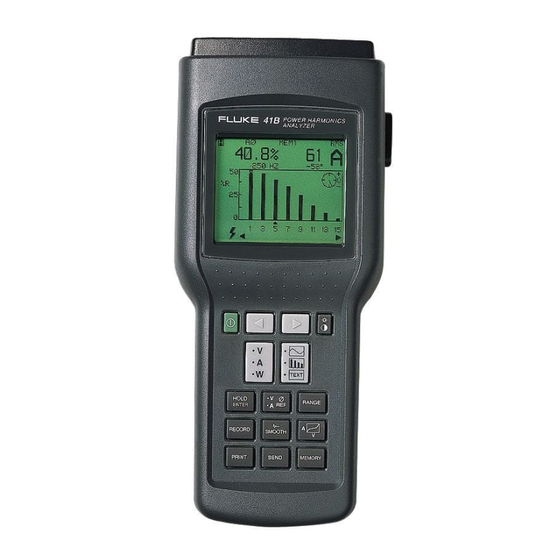
1-5. Description The Fluke 39 and 41B are handheld Testers used to measure voltage and current at power line and harmonic frequencies. Using these inputs, the Tester automatically calculates power and a wide range of other measurements useful in determining harmonic distortion levels and sources. -
Page 15: Operating Instructions
Soft Carrying Case 1-8. Operating Instructions Operating instructions for the Fluke 39 and 41B can be found in the Users Manual (Fluke PN 942847). See How to Obtain Parts on page 6-1. 1-9. Specifications Accuracy is specified for a period of one year after calibration. - Page 16 39/41B Service Manual Input Range: 1.00 mV (A) to 1400 mV rms (A) (ac + dc) 1.0 mV (A) to ±2000 mV (A) peak Basic Accuracy: rms (ac + dc): ±(0.5% + 3 digits); 6-65 Hz + probe specs peak, dc: ±(2% + 4 digits) + probe specs...
- Page 17 Introduction and Specifications Specifications Other Measurement Specifications Measurement Function Range/Resolution Accuracy Input Bandwidth: (-0.5 dB) DC, 6 Hz to 2.1 kHz ±4% Crest Factor (CF): (Using Smooth 1.00 to 5.00 %20): ±0.02 Power Factor (PF): 0.00 to 1.00 Power Factor Displacement (PFD): 0.00 to 0.29 Unspecified ±0.04...
- Page 18 39/41B Service Manual General Specifications Size: 9.2 x 3.9 x 2.5 inches (234 x 100 x 64 mm) Weight: 2.0 lbs (1 kg) Input Connectors: Voltage: 2 shrouded banana jacks (4 mm) Current Probe: 1 shrouded BNC jack Battery: Type: 4 Alkaline "C"...
- Page 19 Introduction and Specifications Specifications Safety Designed for 600V measurements on industrial power distribution circuits. ! Overload Protection: Voltage or Current Probe Input: 600V, maximum Surge Protection: 6 kV per IEC 1010-1 Maximum Voltage Isolation to Earth: 600V from any terminal Protection Levels: IEC 1010-1, Pollution Degree 2, Installation Category III, Material Group II, 600V...
- Page 20 39/41B Service Manual 1-10...
-
Page 21: Theory Of Operation
Programmable Logic Device ............2-10 2-34. SRAMs (U5,U6,U7) ..............2-13 2-35. EPROM (U4) ................2-13 2-36. EEPROM (U11)................2-13 2-37. Serial EEPROM (U22) ..............2-13 2-38. Keypad ..................... 2-13 2-39. Display ..................... 2-13 2-40. LCD Module................2-13 2-41. BackLight ..................2-14... - Page 22 39/41B Service Manual 2-42. Contrast Control - EEPOT (U8) ..........2-14 2-43. Optical Interface (Model 41B Only)..........2-14 2-44. Transmitter................... 2-14 2-45. Receiver ..................2-14...
-
Page 23: Introduction
Introduction 2-1. Introduction Chapter 2 provides circuit descriptions for the Fluke 39 Power Meter and Fluke 41B Power Harmonics Analyzer. First, the Tester is described in general terms with a Functional Block Description. Then each block is detailed further with Detailed Circuit descriptions. - Page 24 39/41B Service Manual t1f.eps Figure 2-1. Overall Functional Block Diagram...
-
Page 25: Circuit Operation
DSP. The optical interface communicates with a PC or printer, and it provides a sufficient voltage standoff for safety reasons. The Fluke PM9080 interface cable is required to complete the interface to a PC or printer. -
Page 26: Normal Operation
39/41B Service Manual 8. About 140 ms after the power button is first pressed, a dark screen is displayed. If the power button is held down during power-up, a checkerboard test pattern then appears on the LCD. When the button is released, the instrument resumes normal operation. -
Page 27: Vee
Theory of Operation Circuit Descriptions output to 3.3V dc ±5%. The feedback voltage is ≈1.224V dc. Transformer T1 and capacitor C63 filter the output of U30. U30 has an internal Undervoltage Lockout circuit. The circuit monitors the supply voltage and allows normal operation for voltages greater than 3.75V dc (typical) with 0.25V dc of hysteresis. -
Page 28: Low Battery Detection
39/41B Service Manual 2-15. Low Battery Detection The low battery detection circuit monitors the battery voltage and sends a signal to the microcontroller when the battery voltage falls below 4.22 volts. R49 and R53 set the reference for the circuit to 1.47 volts. R52 and R30 divide the battery voltage down to stay within the common mode range of the op amp. -
Page 29: Anti-Alias Filter
Theory of Operation Circuit Descriptions Table 2-1. Voltage Gains Range Signal Gain Software Limit 256V X4 (low) Four 200V peak 512V X2 (low) 500V peak 1024V X1 (low) 937V peak Table 2-2. Current Gains Control Signals Range Gain Software Limit X10A X10B 20A peak... -
Page 30: Digital Kernel
In the case of the Fluke 39/41B, U3 is broken into six relatively simple sections. Several of the sections share common inputs. Figure 2-2 is a block diagram of the internal circuits of the PLD. - Page 31 Theory of Operation Circuit Descriptions DSPCLOCK KEYPAD INTERRUPTS INTERFACE IRQA* CS_LCD* MEMORY RA13 DECODE INC_EEPOT* CS_EEPOT* CS_GAIN* EEPOT CS_EEPROM* INTERFACE CS_BOOTROM* CS_SRAM* SERIAL DOUT_AMPS SHIFT REGISTER DOUT_VOLTS DOUT DOUT_EESER CS_AD ATOD_EESER ATOD_EESER CS_EESER t2f.eps Figure 2-2. PLD Block Diagram 2-29. Memory Decoding The signals A15, A14, A5, A4, PS*, DS*, XY, and WR* are used to map out the SRAM, EPROM, EEPROM, Gain Latch, EEPOT, and LCD in program and data space.
- Page 32 39/41B Service Manual Table 2-4 is a truth table for the selection of the various devices in the Tester. Table 2-4. Logic Truth Table Device Signal SRAM CS_SRAM SRAM CS_SRAM EEPROM CS_EEPROM EPROM CS_BOOTROM CS_LCD EEPOT INC_EEPOT EEPOT CS_EEPOT LATCH CS_GAIN 2-30.
-
Page 33: Srams (U5,U6,U7)
DSP. By applying a logic low to the columns one by one, the DSP can determine the pressed key. 2-39. Display The Fluke 39/41B display consists of two circuits, the LCD Module and the Contrast Control. 2-40. LCD Module The LCD module is a complete system. -
Page 34: Backlight
CR6. The current through CR6 should be ≈11 mA at ambient. 2-45. Receiver Q5 is a photo transistor used to receive the signal provided by the Fluke 41B’s RS-232 cable. It senses the infrared light from the infrared LED in the optional interface cable. -
Page 35: General Maintenance
Chapter 3 General Maintenance Title Page 3-1. Introduction ..................3-3 3-2. Warranty Repairs and Shipping Information ........3-3 3-3. General Maintenance Information............3-3 3-4. Required Equipment ................ 3-3 3-5. Static-Safe Handling ................ 3-3 3-6. Cleaning....................3-4 3-7. Disassembling the Tester ..............3-4 3-8. - Page 36 39/41B Service Manual...
-
Page 37: Introduction
General Maintenance Introduction Warning Service procedures in this chapter should be performed by qualified personnel only. To avoid electrical shock, do not service this product unless you are qualified to do so. 3-1. Introduction This chapter provides handling, cleaning, disassembly, and assembly instructions. 3-2. -
Page 38: Cleaning
39/41B Service Manual Follow these two rules for handling static-sensitive devices: 1. Handle all static-sensitive components at a static-safe work area. Use grounded static-control table mats on all repair benches, and always wear a grounded wrist strap. Handle boards by their nonconductive edges only. Store plastic, vinyl, and Styrofoam objects outside the work area. -
Page 39: Removing The Pca And Input Module
General Maintenance Disassembling the Tester t3f.eps Figure 3-1. Removing the Case Bottom 3-9. Removing the PCA and Input Module Caution To avoid contaminating the pca with oil from your fingers, handle the pca by its edges or wear gloves. A contaminated pca may not cause immediate instrument failure in controlled environments. -
Page 40: Removing The Lcd Module
39/41B Service Manual t4f.eps Figure 3-2. Flex Cable Connector 3-10. Removing the LCD Module After you have removed the case bottom and pca, use the following procedure to remove the LCD module: 1. Remove the four Phillips screws from the corners of the LCD module. -
Page 41: Reassembling The Case Bottom
General Maintenance Reassembling the Tester 2. Rotate the pca into the case top, aligning the holes in the pca over the six bosses. Make sure that the pca is pressed down over the ribs of the boss in the upper right corner of the case top. - Page 42 39/41B Service Manual...
-
Page 43: Performance Testing And Calibration
Chapter 4 Performance Testing and Calibration Title Page 4-1. Introduction ..................4-3 4-2. Required Equipment................4-3 4-3. Performance Tests ................4-4 4-4. Warming-Up the Tester ..............4-4 4-5. Checking the Display Pixels ............4-4 4-6. Testing Voltage Performance ............4-4 4-7. - Page 44 39/41B Service Manual...
-
Page 45: Introduction
Frequency: 60 Hz Accuracy: 0.5% Phase accuracy: 0.5 degrees @ 60 Hz sourcing 10 mV and 5 V inputs * A second calibrator, phase meter and dual channel signal generator is not required when using one Fluke 5500A Multi-Product Calibrator. -
Page 46: Performance Tests
39/41B Service Manual 4-3. Performance Tests If the Tester passes the following tests, the meter is in proper operating condition. If the meter fails any of the performance tests, calibration adjustment and/or repair is needed. 4-4. Warming-Up the Tester Before performing any of the following performance tests, the Tester should be allowed to sit for four hours in an environment of 18-28°... -
Page 47: Testing Amps Performance
Performance Testing and Calibration Performance Tests Table 4-2. Volts Performance Performance Limits Calibrator Output Fluke 39/41B V rms V pk V dc V dc Range 5.00V 15.0V 14.4 15.6 65.0V 63.4 66.6 130.0V 127.1 132.9 208.0V 350.0V 480.0V 1000 600.0V... - Page 48 39/41B Service Manual Variable Phase Out Phase Lock In Calibrator “A” Calibrator “B” 5V – 100V ac 30 mV – 1.4V ac Output Output POWER HARMONICS ANALYZER ® Phase Meter Signal t5c.eps Figure 4-1. Watts Performance Test Configuration...
- Page 49 9. Verify the readings are within the minimum and maximum limits specified in Table 4-3. Note It is normal for the tester to display “**OL*%THD*” with a VDC input. Table 4-3. Amps Performance Performance Limits Calibrator Output Fluke 39/41B A rms A pk A dc mV dc Range 1.00 mV 0.94 1.06...
-
Page 50: Testing Watts, Va, Var Performance
39/41B Service Manual 4-8. Testing Watts, VA, VAR Performance Perform the following procedure to test the watts, VA, and VAR functions of the Tester. Warning Ensure that the calibrator is in standby mode before making any connection between the calibrator and Tester. dangerous voltages may be preSent on the leads and connectors. -
Page 51: Testing Memory Mode Performance (Model 41B Only)
Performance Testing and Calibration Performance Tests 4-10. Testing Memory Mode Performance (Model 41B Only) 1. Using the equipment setup from the previous performance test, apply the last set of values from Table 4-4 to the Tester. 2. Press m. 3. Using < > and E, Clear, store, and recall the waveform in memory. 4-11. -
Page 52: Testing Harmonics Amps Performance
39/41B Service Manual Table 4-5. Harmonics Performance for Volts Fluke Fluke 5500A Output Performance Limits Tester Amplitude Harmonic Phase Harmonic Amplitude Phase (deg.) Cursor No. 7.00 -10.00 7.00 -20.00 7.00 -30.00 7.00 -40.00 7.00 -50.00 7.00 -60.00 4-12. Testing Harmonics Amps Performance Note Make sure that the unit is set to "THD % RMS"... -
Page 53: Testing Serial I/O Performance (Model 41B Only)
Performance Testing and Calibration Calibrating the Tester Table 4-6. Harmonics Performance for Amps Fluke Fluke 5500A Output Performance Limits Tester Amplitude Harmonic Phase Harmonic Amplitude Phase (mV) (deg.) Cursor No. 20.00 10.00 19.1 20.9 20.00 20.00 19.1 20.9 20.00 30.00 19.1... -
Page 54: Calibrating The Tester
39/41B Service Manual 4-14. Calibrating the Tester The Tester allows closed-case calibration using known reference sources. The meter automatically prompts you for the required reference signals, measures them, calculates the correction factors, and stores the correction factors in the nonvolatile calibration memory. - Page 55 Performance Testing and Calibration Calibrating the Tester f6f.eps Figure 4-2. Battery Removal 3. In order for the Tester to remain on while replacing the battery door, remove the battery shunt spring and reinsert it with the spring’s straight edge on the battery side of the plastic wall (Figure 4-3).
- Page 56 39/41B Service Manual t7f.eps Figure 4-3. Battery Spring Adjustment 5. With the instrument in an upright position, the Cal Enable switch pads are in the largest and leftmost hole (Figure 4-4). Using a small flat-blade screwdriver or equivalent blunt-tipped conductive object, short together the two Cal Enable pads.
- Page 57 Performance Testing and Calibration Calibrating the Tester 6. Reinstall the battery access lid on the instrument. See Figure 4-2. The display also provides information for the RANGE that is being calibrated, the voltage to APPLY to the Tester inputs, and the resulting calibration FACTOR. All ranging is automatically taken care of by the Tester and only the calibration voltage needs to be supplied.
-
Page 58: Making Calibration Adjustments
39/41B Service Manual 4-17. Making Calibration Adjustments The calibration step being performed is identified by an arrow on the left side of the display. Each step calls for either a connection to be made or a known voltage applied to the input of the Tester. -
Page 59: Exiting The Calibration Mode
Performance Testing and Calibration Calibrating the Tester 10. Disconnect the calibrator from the Clamp Probe BNC connector. Connect calibrator HI and LO outputs to the V and COM inputs of the Tester. Press E. Warning Dangerous voltages will be present on the calibration source and connecting cables during the following steps. -
Page 60: Setting The Minimum Contrast Level
39/41B Service Manual 4-19. Setting the Minimum Contrast Level A minimum contrast level needs to be set whenever an LCD module, pca or the serial EEPROM (U22) is replaced. This setting provides a minimum useful level so that a user may not inadvertently set the screen blank. -
Page 61: Troubleshooting
Chapter 5 Troubleshooting Title Page 5-1. Introduction ..................5-3 5-2. General Troubleshooting..............5-3 5-3. Starting with a Dead Tester (Model 41B Only)....... 5-3 5-4. Troubleshooting the Power Supply ............5-5 5-5. Troubleshooting the Digital Section ............ 5-5 5-6. Troubleshooting the Digital Kernel ..........5-6 5-7. - Page 62 39/41B Service Manual...
-
Page 63: Introduction
Troubleshooting Introduction 5-1. Introduction This chapter describes troubleshooting procedures that can be used to isolate problems with the Tester. These procedures deal primarily with the digital section of the Tester. Due to the simplicity of the Analog section, only theory of operation is provided to support analog troubleshooting. - Page 64 39/41B Service Manual P2, Pin1 AMPS SGND (U15, Pin 16) (Junc. C63 and T1) AMPS IN VREF (U14, Pin 9) Enable (U17, Pin 4) (P4) V IN PWR_SW2 COMM (R87, Pin 2) PWR_SW1 (R26, Pin 1) (U25, Pin 7) -22 Vdc...
-
Page 65: Troubleshooting The Power Supply
Troubleshooting Troubleshooting the Power Supply 5-4. Troubleshooting the Power Supply After pressing o, check the power supply voltages against the supply range values in Table 5-2. If the power supplies do not come on, the problem could be with the power-on circuit itself. -
Page 66: Troubleshooting The Digital Kernel
39/41B Service Manual 5-6. Troubleshooting the Digital Kernel To isolate a problem within the Digital Kernel, proceed as follows: 1. Check for loose or unsoldered pins on U2 through U7. 2. Check all VCC pins on U2 for 3.3V. Because the VCC pins on the DSP supply power to different areas of the chip, any VCC pin that does not receive 3.3V when o... -
Page 67: Troubleshooting The A/D Converter Output
Troubleshooting Troubleshooting the Digital Section 0 ns 100 ns 200 ns 300 ns CLOCK 6.20 Min/Max 263.15 Min/Max A0-A15, Address Bus, DS, PS, XY DS*, PS*, X/Y* 15 Min/Max 15 Min/Max 250 Min/Max CS_BOOTROM 285.46 Min/Max 5.05 Min/Max 125 Min/Max 281.96 Min/Max DATA t16i.eps... - Page 68 39/41B Service Manual • SRD (U2-38) labeled ‘DOUT’ - serial data received from the MUX in U3. When the instrument is collecting data in normal operation mode, the above four waveforms can be observed with the following timing. 241,824 Hz 426.62 ns...
-
Page 69: Troubleshooting The Keypad
Troubleshooting Troubleshooting the Digital Section • SCK* (U14/U15-13 and U3-20) - A complemented version of SCK coming from the DSP chip. • CS_AD* (U14/U15-1 and U3-17) - The chip select signal to the A/Ds which causes the A/Ds to sample and convert the result. •... -
Page 70: Troubleshooting The Range Control Circuit
39/41B Service Manual in Chapter 7. If the row line is driven low for an incorrect column line, then there is some external problem, possibly a keypad or elastomeric interconnect problem. 5-9. Troubleshooting the Range Control Circuit The Tester’s measurement range can be changed manually or automatically. If the Tester is unable to change ranges, proceed with the following steps: 1. -
Page 71: Troubleshooting The Eeprom
Troubleshooting Troubleshooting the Digital Section 5-10. Troubleshooting the EEPROM The EEPROM (U11) is used for waveform storage and is only installed on the Model 41B. To isolate waveform storage problems, proceed with the following: 1. Verify that R82 and R84 are correct and installed. Also, verify that R83 and R85 are absent. -
Page 72: Troubleshooting The Lcd Display Module
39/41B Service Manual 5-11. Troubleshooting the LCD Display Module To isolate a problem when the LCD display appears dead, do the following: 1. First, verify that the display module is properly connected to the main circuit board. Make certain that the flex cable is not twisted or at an angle as it enters the molex connector of either the LCD module or the main circuit board. -
Page 73: Troubleshooting The Serial Eeprom
EEPROM (U22) is probably faulty. Note In the next step, the Fluke 39 will not display the baud rate or printer type. 2. Reset the instrument to factory default by holding R and pressing O. Then, power the Tester off and back on to bring up the power-up configuration screen. The following menu items should be highlighted: VOLT, WAVE, %RMS, 80I-500S, VOLT, 9.6K, and EPSON. - Page 74 39/41B Service Manual • SCK* line (U22-2) should be changing states at slightly less than a 500 KHz rate. • Data written to the serial EEPROM (U22-3) should be the same as U2-33 (line labeled DIN). • Data read from the serial EEPROM (U22-4) should be the same as the data supplied to the processor (U2-38).
-
Page 75: List Of Replaceable Parts
Chapter 6 List of Replaceable Parts Title Page 6-1. Introduction .................... 6-3 6-2. How to Obtain Parts ................6-3 6-3. Manual Status Information..............6-3 6-4. Newer Instruments ................. 6-4 6-5. Parts Lists ....................6-4... - Page 76 39/41B Service Manual...
-
Page 77: Introduction
Introduction 6-1. Introduction Chapter 6 contains an illustrated list of replaceable parts for the Fluke 39 Power Meter and 41B Power Harmonics Analyzer. Parts are listed by assembly; alphabetized by reference designator. Each assembly is accompanied by an illustration showing the location of each part and its reference designator. -
Page 78: Newer Instruments
39/41B Service Manual 6-4. Newer Instruments Changes and improvements made to the instrument are identified be incrementing the revision letter marked on the affected pca. These changes are documented on a manual supplement sheet which, when applicable, is included with the manual. - Page 79 List of Replaceable Parts Parts Lists Table 6-1. Fluke 39 Final Assembly Reference Fluke Stock Description Tot Qty Notes Designator MAIN PCA 202820 BT1-4 BATTERY,1.5V,0-480MA, ALKALINE SIZE C 423582 SCREW,PH,P,AM THD FORM,STL,4-14,.375 448456 SCREW,PH,P,AM THD FORM,STL,5-14,.812 942946 JUMPER, INPUT, RED...
- Page 80 39/41B Service Manual H1 (4 PL) J2 (BLACK) MP19 J1 (RED) (BLACK) XBT1, 2 (RED) (6 PL) BT1-4 SEE VIEW A MP26 (2 PL) MP28 VIEW A FLUKE-39 T&B t10f.eps Figure 6-1. Fluke 39 Final Assembly...
- Page 81 List of Replaceable Parts Parts Lists Table 6-2. Fluke 39 A1 Main PCA Reference Fluke Stock Description Tot Qty Notes Designator C1, C6 CAP,CER,750PF,+-1%,50V,C0G,0805 867643 CAP,CER,1000PF,+-1%,50V,C0G,1206 867668 C3, C73 CAP,CER,1000PF,+-1%,50V,C0G,1206 867668 CAP,CER,100PF,+-1%,50V,C0G,0805 867650 C5, C7, C13, CAP,CER,0.1UF,+-10%,25V,X7R,1206 747287 C15, C16, C18,...
- Page 82 39/41B Service Manual Table 6-2. Fluke 39 A1 Main PCA (cont) Reference Fluke Stock Description Tot Qty Notes Designator P5,P7 SOCKET,SINGLE,PWB,FOR 0.026-0.033 PIN 811539 Q2, Q3, Q13-15 TRANSISTOR,SI,NPN,SMALL SIGNAL,SOT-23 912469 Q4, Q9, Q12 TRANSISTOR,SI,N-DMOS FET,SOT-23 927538 Q6,Q7 TRANSISTOR,SI,NPN,SMALL SIGNAL,SOT-23 742676...
- Page 83 List of Replaceable Parts Parts Lists Table 6-2. Fluke 39 A1 Main PCA (cont) Reference Fluke Stock Description Tot Qty Notes Designator RES,CERM,6.98K,+-1%,.125W,100PPM,1206 929919 RES,CERM,17.8K,+-1%,.125W,100PPM,1206 929930 RES,CERM,24.9K,+-1%,.125W,100PPM,1206 867689 RES,CERM,29.4K,+-1%,.125W,100PPM,1206 929935 RES,CERM,37.4K,+-1%,.125W,100PPM,1206 867486 RES,CERM,20K,+-1%,.125W,100PPM,1206 927421 RES,CERM,3.3,+-5%,.125W,400PPM,1206 867502 RES,CERM,220K,+-5%,.125W,200PPM,1206 746750 RES,CERM,1M,+-1%,.125W,100PPM,1206 836387 R59, R80 RES,CERM,10,+-5%,.125W,200PPM,1206...
- Page 84 39/41B Service Manual Table 6-2. Fluke 39 A1 Main PCA (cont) Reference Fluke Stock Description Tot Qty Notes Designator U16-18 IC,OP AMP,DUAL,PICOAMP IB,SO8 910836 IC,CMOS,TIMER,LOW POWER,SO8 930151 U21, U25 IC,OP AMP,DUAL,LOW POWER,SOIC 867932 IC,EEPROM,SERIAL,64 X 16,LO V,SO8 929802 IC,+5V TO -5V CONVERTER,SWTCH CAP,SO8 929844 IC,V REF,SHUNT,1.2 V,2%,150 PPM,SOT23...
- Page 85 List of Replaceable Parts Parts Lists FLUKE 39-4001 (Sheet 1 of 2) t11f.eps Figure 6-2. Fluke 39 A1 Main PCA 6-11...
- Page 86 39/41B Service Manual FLUKE 39-4001 (Sheet 2 of 2) t12f.eps Figure 6-2. Fluke 39 A1 Main PCA (cont) 6-12...
- Page 87 List of Replaceable Parts Parts Lists Table 6-3. Fluke 41B Final Assembly Reference Fluke Stock Description Tot Qty Notes Designator MAIN PCA 202827 BT1-4 BATTERY,1.5V,0-480MA, ALKALINE SIZE C 423582 SCREW,PH,P,AM THD FORM,STL,4-14,.375 448456 SCREW,PH,P,AM THD FORM,STL,5-14,.812 942946 JUMPER, INPUT, RED...
- Page 88 39/41B Service Manual Table 6-3. Fluke 41B Final Assembly (cont) Reference Fluke Stock Description Tot Qty Notes Designator CABLE,FLAT,JUMPER,24COND,.039SP,1.30 936992 XBT1, XBT2 CONTACT, BATTERY 936752 NOTES: 1. ACCESSORY PACK INCLUDES THE FOLLOWING ITEMS: MP1 - TEST LEAD,SI,R/A-STRT,BANANA,RED,TL24 - 927798 - 1...
- Page 89 H1 (4 PL) SEE VIEW B MP19 XBT1, 2 (BLACK) (RED) (6 PL) BT1-4 (RED) J1 SEE VIEW A (BLACK) J2 MP27 (2 PL) MP32 MP19 VIEW B VIEW A FLUKE-41B T&B t13f.eps Figure 6-3. Fluke 41B Final Assembly 6-15...
- Page 90 39/41B Service Manual Table 6-4. Fluke 41B A1 Main PCA Reference Fluke Stock Description Tot Qty Notes Designator C1, C6 CAP,CER,750PF,+-1%,50V,C0G,0805 867643 CAP,CER,1000PF,+-1%,50V,C0G,1206 867668 C3, C73 CAP,CER,1000PF,+-1%,50V,C0G,1206 867668 CAP,CER,100PF,+-1%,50V,C0G,0805 867650 C5, C7, C13, CAP,CER,0.1UF,+-10%,25V,X7R,1206 747287 C15, C16, C18, 747287 C20-24, C26-32,...
- Page 91 List of Replaceable Parts Parts Lists Table 6-4. Fluke 41B A1 Main PCA (cont) Reference Fluke Stock Description Tot Qty Notes Designator DIODE,SI,30 PIV,1.1 AMPS,SCHOTTKY 782573 CR10 DIODE,SI,BV=75V,IO=250MA,SOT-23 830489 L1-5 FERRITE CHIP,60 OHM @100 MHZ,1806 944645 CONN,FLAT FLEX,1MM CTR,RT ANG,24 POS...
- Page 92 39/41B Service Manual Table 6-4. Fluke 41B A1 Main PCA (cont) Reference Fluke Stock Description Tot Qty Notes Designator RES,CERM,1K,+-5%,.125W,200PPM,1206 745992 R28, R32, R45 RES,CERM,1K,+-1%,.125W,100PPM,1206 783241 RES,CERM,464K,+-1%,.125W,100PPM,1206 929898 RES,CERM,510K,+-5%,.125W,200PPM,1206 746800 R33, R70, R84 RES,CERM,0,+.05 MAX,.125W,1206 810747 RES,CERM,150,+-1%,.125W,100PPM,1206 772780 RES,CERM,47K,+-5%,.125W,200PPM,1206 746685 RES,CERM,4.7K,+-5%,.125W,200PPM,1206...
- Page 93 List of Replaceable Parts Parts Lists Table 6-4. Fluke 41B A1 Main PCA (cont) Reference Fluke Stock Description Tot Qty Notes Designator RES,CERM,12.1,+-1%,0.1W,100PPM,0805 930081 THERMISTOR,POS,1.1K,+-20%,25 C 867192 INDUCTOR,100UH,+-20%,0.51ADC 929729 INDUCTOR,200UH,+-20%,0.36ADC 929732 IC,CMOS,OCTAL D F/F,+EDG,W/3 ST,SOIC 929869 IC,DIGITAL SIGNAL PROC,LV,24 BIT,PQFP...
- Page 94 39/41B Service Manual FLUKE 41B-4001 (Sheet 1 of 2) t14f.eps Figure 6-4. Fluke 41B A1 Main PCA 6-20...
- Page 95 List of Replaceable Parts Parts Lists FLUKE 41B-4001 (Sheet 2 of 2) t15f.eps Figure 6-4. Fluke 41B A1 Main PCA (cont) 6-21...
- Page 96 39/41B Service Manual 6-22...
-
Page 97: Schematic Diagrams
Chapter 7 Schematic Diagrams Title Page A1 Main PCA (Fluke 39 and 41B)..............7-3... - Page 98 39/41B Service Manual...
- Page 99 FOR ASSEMBLY AND REFERENCE DESIGNATION DRAWING SEE FLUKE 39 & 41B-4001 DRAWINGS. R28 IS LOADED FOR BOTH THE 39 AND 41B, SEE SHEET 3. R56, R39, Q21, R36, CR6, C11, Q5, R32, C12, U20, Q1, R25, C10, R29, CR1 ARE LOADED ON THE FLUKE 41B ONLY, SEE SHEET 3.
- Page 100 PWR_SW2 EE_UPLOW VBT+ A<0> SEL1 8200PF BL_A LCD_E FLUKE 4X-1021 (2 of 6) DE COUPLING CAPACITORS DSP56003 DSP56003 PVCC LM358 9313 SRAM SRAM SRAM 93C46 7032 7032 27256 28256 DSP56003 Figure 7-1. A1 Main PCA (Fluke 39 and 41B) (cont)
- Page 101 100K MMBT5087 220K LM358DT RESET LM4041EIM3-1.2 29.4K RESET* BL_K BAV99 MMBT6429 100K MMBT6429 MMBT6429 LM358DT BL_CT 100K 620K MMBT6429 MMBT6429 100K MMBT6429 FLUKE 4X-1021 4.7K 100K 100K (3 of 6) Figure 7-1. A1 Main PCA (Fluke 39 and 41B) (cont)
- Page 102 VREF AD706 226K 121K AD706 VREF 36.5K 499K MMBT3904 VREF 47PF 100PF 1000V 750PF 499K DG444DY DG444DY DG444DY DG444DY MMBT3904 DG444DY X1A_AMP X10A_AMP FLUKE 4X-1021 (4 of 6) X1B_AMP X10B_AMP Figure 7-1. A1 Main PCA (Fluke 39 and 41B) (cont)
- Page 103 15MEG 220NF TLC555CD BAV99 - 2 2 V BAT54S LM2936M CAP+ CAP- MAX660 AD680 AD820BR VOUT VREF TEMP BOOST 100NF VOUT FLUKE 4X-1021 CAP+ (5 of 6) CAP- LTC1046 2N7002 Figure 7-1. A1 Main PCA (Fluke 39 and 41B) (cont)
- Page 104 PHASE REF PWR_SW1 PWR_SW2 RANGE RECORD SMOOTH PRINT SEND MEMORY KEYS ( PRINT, SEND AND MEMORY) , ON MODEL 41 ONLY. ON/OFF FOR REFERENCE ONLY FLUKE 4X-1021 (6 of 6) Figure 7-1. A1 Main PCA (Fluke 39 and 41B) (cont)
Need help?
Do you have a question about the 39 and is the answer not in the manual?
Questions and answers