Nikon SB-5000 Reference Manual
Hide thumbs
Also See for SB-5000:
- User manual (120 pages) ,
- Manual (16 pages) ,
- Fast track manual (9 pages)
Table of Contents
Advertisement
Quick Links
Advertisement
Table of Contents

Related Manuals for Nikon SB-5000


Summary of Contents for Nikon SB-5000
- Page 1 Speedlight SB - 5000 Reference Manual Nikon Manual Viewer 2 Install the Nikon Manual Viewer 2 app on your smartphone or tablet to view Nikon digital camera manuals, anytime, anywhere. Nikon Manual Viewer 2 can be downloaded free of charge from the App Store and Google Play.
-
Page 2: Preparation
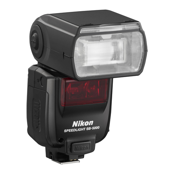
Preparation About the SB-5000 and This Reference Manual Thank you for purchasing the Nikon Speedlight SB-5000. To get the most out of your Speedlight, please read the user’s manual and the reference manual (this manual) thoroughly before use. How to find what you are looking for... - Page 3 The SB-5000 is a high-performance Speedlight compatible with Nikon Creative Lighting System (CLS) with a guide number of 34.5/113 (ISO 100, m/ft) (at the 35 mm zoom head position in Nikon FX format with standard illumination pattern). In addition to conventional optical control, radio control is possible in wireless multiple flash-unit photography.
- Page 4 • The SB-5000 cannot be used with IX-Nikkor lenses. A collection of example photos “A collection of example photos” provides an overview of the SB-5000’s flash photography capabilities with example images. To download the PDF file of “A collection of example photos”, access the link below.
- Page 5 Terminology ■ Nikon Creative Lighting System (CLS) A lighting system that enables various flash photography functions with improved communication between Nikon Speedlights and cameras ■ Unified flash control A function that enables flash function settings to be shared by the Speedlight and the camera ■...
- Page 6 ■ Auto aperture flash mode Non-TTL auto flash mode with aperture priority; the Speedlight measures the reflected flash and controls the flash output according to the reflected flash data and the lens and camera information ■ Non-TTL auto flash mode Auto flash mode without TTL;...
- Page 7 Link mode Enables selection of communication type between Nikon Speedlight and camera. Available selections are pairing and PIN code. Pairing Speedlight and a camera paired beforehand communicate.
- Page 8 Default settings Function and mode settings at the time of purchase ■ Illumination patterns Control types of light falloff at edges; the SB-5000 provides 3 illumination patterns, standard, even and center-weighted. ■ Test firing Flash firing to determine whether the Speedlight fires properly ■...
- Page 9 ■ FX format/DX format Nikon digital SLR camera image area types (FX format: 36 × 24, DX format: 24 × 16) ■ Guide number (GN) The amount of light generated by a flash unit; as the number increases, the light extends further. There is a relation represented by an equation, GN = flash-to-subject distance (m or ft) ×...
-
Page 10: Flash Photography
Q&A Index You can search for specific explanations according to objective. Flash photography 1 Using the SB-5000 attached to a camera’s accessory shoe Question Key phrase Which flash mode can I take pictures with? Flash modes How can I take pictures in the simplest way? - Page 11 How do I take pictures with the SB-5000 and CLS-compatible COOLPIX a COOLPIX camera compatible with wireless camera multiple flash-unit photography? How can I use the SB-5000 as the master flash Master flash unit unit? How can I use the SB-5000 as a remote flash Remote flash unit...
- Page 12 Settings and operations Question Key phrase What kind of batteries do I use in the Speedlight? Compatible batteries B-17 How long is the recycling time and how many Minimum number of flashes are possible with each fresh set of flashes/recycling time for H-23 batteries? each battery type...
-
Page 13: Table Of Contents
Table of Contents Preparation About the SB-5000 and This Reference Manual........A-1 Q&A Index ........................A-9 For Your Safety......................A-16 Wireless Regulation Data.................A-20 Check before Use ....................A-22 Operation Speedlight Parts ....................... B-1 Settings and the LCD .................... B-5 Menu ........................B-11 Unified Flash Control ..................B-14 Basic Operations .................... - Page 14 Wireless Multiple Flash-unit Photography SB-5000 Wireless Multiple Flash-unit Photography Examples ......................D-1 SB-5000 Wireless Multiple Flash-unit Photography Using Radio Control ....................D-4 SB-5000 Wireless Multiple Flash-unit Photography Using Optical Control ....................D-5 SB-5000 Functions for Wireless Multiple Flash-unit Photography ....................D-7 Setting the Master Flash Unit .................
- Page 15 Functions Switching Illumination Patterns ..............E-2 Bounce Flash Operation ..................E-4 Taking Close-up Photographs ...............E-11 Flash Photography with Color Filters ............E-14 Flash Photography Support Functions ............E-20 • Flash exposure compensation .............E-20 • Power zoom function ................E-22 • AF-assist illumination .................E-24 •...
- Page 16 Tips on Speedlight Care and Reference Information Troubleshooting ..................... H-1 Guide Number, Aperture and Flash-to-subject Distance ..... H-6 Tips on Speedlight Care ..................H-7 Notes on Batteries ....................H-9 About the LCD Panel ..................H-10 Updating Firmware .....................H-11 Optional Accessories..................H-12 Specifications ......................H-20 Index ..........................H-31 A-15...
-
Page 17: For Your Safety
For Your Safety To prevent damage to your Nikon product or injury to yourself or others, read the following safety precautions in their entirety before using this equipment. Keep these safety instructions where all those who use the product will read them. - Page 18 " Do not handle with wet hands. Failure to observe this precaution could result in electric shock. " Do not use in the presence of flammable gas or dust. Use of electronic equipment in the presence of flammable gas or dust could result in explosion or fire.
- Page 19 • Do not short or disassemble batteries or attempt to remove or otherwise damage the battery insulation or casing. • Do not expose to flame or excessive heat, immerse in or expose to water, or subject to physical force. • Do not transport or store with metal objects such as necklaces or hairpins.
- Page 20 Notice for customers in Canada CAN ICES-3B / NMB-3B Notice for customers in Europe This symbol indicates that electrical and electronic equipment is to be collected separately. The following apply only to users in European countries: • This product is designated for separate collection at an appropriate collection point.
-
Page 21: Wireless Regulation Data
Nikon will not be held could void the user’s authority liable for use of these features to operate the equipment. - Page 22 Nikon accepts following measures: no responsibility for the use of • Reorient or relocate the receiving this device in countries other than antenna.
-
Page 23: Check Before Use
Take trial shots before photographing important occasions such as weddings or graduations. Use your Speedlight with Nikon equipment The Nikon Speedlight SB-5000’s performance has been optimized for use with Nikon brand cameras/accessories including lenses. Cameras/accessories made by other manufacturers may not meet Nikon’s criteria for specifications, and incompatible cameras/accessories could damage the SB-5000’s components. - Page 24 Visit these sites to keep up-to-date with the latest product information, tips, answers to frequently asked questions (FAQs) and general advice on digital imaging and photography. Additional information may be available from the Nikon representative in your area. See the URL below for contact information: http://imaging.nikon.com/...
- Page 25 A-24...
-
Page 26: Operation
Operation Speedlight Parts... - Page 27 1 Flash head 12 External power source terminal (supplied with 2 Flash head tilting/rotating cover) (0H-18) lock release button (0B-20) 13 Light sensor for non-TTL auto 3 Light sensor window for flash (0C-8, C-11) wireless remote flash (0D-41) 14 External AF-assist illuminator 4 Battery-chamber cover contacts 5 Battery-chamber cover lock...
- Page 28 18 Flash head tilting angle scale 25 Modeling illumination button (0E-4) • Controls modeling illumination (0E-27) 19 Flash head rotating angle scale (0E-4) button • Displays menu settings 20 Sync terminal (0B-11) 21 Sync terminal cover 27 MENU button 22 LCD panel (0B-5) •...
- Page 29 28 Wireless setting button 30 Power switch • Selects control type • Rotate to turn power on • Configurable items vary and off depending on the position • Set the index to choose the of the power switch desired function (0B-8) REMOTE: REMOTE:...
-
Page 30: Settings And The Lcd
Icons on the LCD show the status of settings. Displayed icons vary according to selected flash modes and settings. • The basic control of SB-5000 functions is as follows: Use the rotary multi selector to highlight the item to be configured and choose desired setting. - Page 31 Normal and highlighted display Normal display Highlighted display Highlighted display indicates that the item is being selected. Settings can be changed while highlighted. The LCD returns to normal display as shown at the left after settings are changed and confirmed. Rotary multi selector The rotary multi selector can be operated by pressing up, down, left, right or by rotating it.
- Page 32 (0C-5). ] Zoom head position Pressing the rotary multi selector 4 highlights the zoom head position (0E-22). • The zoom head position is automatically set to match the lens focal length when the SB-5000 is attached to a camera.
- Page 33 ■ Selecting items Pressing the rotary multi selector 1 3 4 2 highlights the items to be configured. In menu and other menus, items can be selected by rotating the rotary multi selector (0B-11, B-24). ■ Changing settings Rotating the rotary multi selector changes the settings for highlighted items.
- Page 34 ■ When the power switch is set to [ON] Single flash-unit mode i-TTL balanced fill-flash Standard i-TTL Auto aperture flash with monitor pre-flashes Auto aperture flash without monitor pre-flashes Non-TTL auto flash with monitor pre-flashes Non-TTL auto flash without monitor pre-flashes Distance-priority manual flash Manual flash Repeating flash...
- Page 35 Radio control master mode Group flash Quick wireless control Multiple flash-unit repeating flash ■ When the power switch is set to [REMOTE] Optical control remote mode Direct remote mode Radio control remote mode Activating key lock Press the MENU button for 2 seconds. The key lock icon appears on the LCD and the dial and buttons are locked.
-
Page 36: Menu
Menu With menu, items to be configured can be selected. Using menu Press the button to display menu. Press the rotary multi selector 1 3 to highlight the item to be configured. • Alternatively, rotate the rotary multi selector to select items. Press the OK button to confirm the selection. - Page 37 menu functions and settings icons Zoom head position Flash mode Flash compensation value/Flash output level in manual flash mode Aperture (in non-TTL auto flash mode) Flash-to-subject distance (in distance-priority manual flash mode) Number of flash firings (in repeating flash mode) Frequency of flash firings (in repeating flash mode) Amount of underexposure due to insufficient flash output (in i-TTL mode, underexposure occurred)
- Page 38 Two-button reset Press the MENU button and the button simultaneously for 2 seconds to reset all settings except menu settings to default. • This resets only the settings for the item to which the power switch is set. • When reset is complete, the LCD is highlighted and then returns to normal display.
-
Page 39: Unified Flash Control
Unified Flash Control When the SB-5000 is attached to a camera compatible with unified flash control, flash function settings can be shared by the SB-5000 and the camera. While the SB-5000 settings can be configured on the camera, the settings configured on the SB-5000 are also applied to the camera. The following settings can be configured. - Page 40 SB-5000. • If flash function settings are made on the SB-5000 when not attached to a camera, the configured settings will be applied to the camera after the SB-5000 is attached.
-
Page 41: Basic Operations
Basic Operations This section covers basic procedures in i-TTL mode in combination with a CLS-compatible camera. STEP Inserting the batteries While pressing the battery- chamber cover lock release, slide the battery-chamber cover and open it. Insert the batteries following the [+] and [−] marks. - Page 42 Compatible batteries and replacement/ recharging When replacing batteries, use 4 fresh AA-size batteries or fully-charged rechargeable batteries of the same brand. Refer to the following table to determine when to replace batteries with fresh ones or recharge batteries according to how long the flash-ready indicator takes to come on. Do not mix old and new batteries or batteries of different types or makes.
- Page 43 LCD and the SB-5000 stops functioning. Replace or recharge batteries. STEP Attaching the SB-5000 to the camera Make sure the SB-5000 and the camera are turned off. Make sure the mounting foot lock lever is on the left (white dot).
- Page 44 Cameras with auto pop-up flash units Turn the SB-5000 on when it is attached to a camera with a built-in, auto pop-up flash unit. When the SB-5000 is turned off, the camera’s built-in flash may pop-up automatically and strike the SB-5000. It is recommended to detach the SB-5000 from the camera when not in use.
- Page 45 Flash head is set at angle. (Flash head is tilted up or rotated to the right or left.) Flash head is tilted down. STEP Turning the camera and SB-5000 on Turn the camera on. Set the SB-5000’s power switch to [ON]. B-20...
- Page 46 FX format; illumination pattern: standard; ISO sensitivity: 100; zoom head position: 24 mm; aperture f-number: 5.6 • Icons on the LCD may differ depending on the SB-5000 settings and the camera and lens in use. SB-5000 flash information...
- Page 47 STEP Selecting the flash mode Press the wireless setting button to choose single flash-unit mode. Press the rotary multi selector 2 to highlight the flash mode. Use the rotary multi selector to display (0B-6). Press the OK button. Changing the flash mode Pressing the rotary multi selector 1 2 or rotating it clockwise changes the available flash mode icons displayed on the LCD.
- Page 48 Make sure that the flash-ready indicator on the SB-5000 or in the camera’s viewfinder is on before taking a picture. • Set the flash compensation value if necessary (0E-20). B-23...
-
Page 49: Menu Items And Settings
Menu Items and Settings Various operations for the SB-5000 can be easily set using the LCD. • Displayed icons vary according to the combination of camera and status of the SB-5000. • Depending on functions in use, some menu items and settings do not function even though they can be configured and set (for example, flash mode deselection in remote mode). - Page 50 Press the rotary multi selector 1 3 to highlight the desired setting, and then press the OK button. • Press the rotary multi selector 4 to return display to menu item selection. Press the MENU button to close the menu settings. •...
- Page 51 FX/DX format selection Enables selection of image area settings when the zoom head position is manually set DX: Automatically set according to the camera’s image area FX: Nikon FX format (36 × 24) DX: Nikon DX format (24 × 16) B-26...
- Page 52 AF-assist illumination/canceling flash function (0E-24) ON: Both AF-assist illumination and flash function activated OFF: AF-assist illumination canceled, flash function activated AF ONLY: AF-assist illumination activated, flash function canceled (only AF-assist illuminator lights up) ISO sensitivity manual setting Enables manual setting of ISO sensitivity within the range of 3 to 8000 when ISO sensitivity information has not been received from the camera (non-CLS compatible SLR camera is in use)
- Page 53 PIN code setting (0D-17) Displays current 4-digit PIN code. PIN codes can also be entered with the rotary multi selector. 0000 Remote flash unit name (0B-29, D-11) Displays registered name in remote mode. Up to 8 characters can be entered. SB-5000 B-28...
- Page 54 1 character DEL: Delete 1 character Available characters OK: Confirm entry Setup menu Basic settings to make using the SB-5000 easier Illumination pattern (0E-2) CW: Center-weighted STD: Standard EVEN: Even Test firing flash output level in i-TTL mode (0E-26) M1/128: Approx. 1/128 M1/32: Approx.
- Page 55 Canceling power zoom function (0E-23) ON: Power zoom function canceled (zoom head position must be manually set) OFF: Power zoom function activated (manual setting of zoom head position not possible) Zoom head position in bounce flash photography (0E-6) TELE: Locked at the maximum telephoto position WIDE: Locked at the maximum wide-angle position Cooling system (0E-30) Enables activation and canceling of the cooling system.
- Page 56 Flash-ready indicator and AF-assist illuminator in remote mode (0D-45) Enables selection of flash/light up of flash-ready indicator and AF-assist illuminator in remote mode to save power ALL: Back indicator lights up, front illuminator flashes slowly in remote mode REAR: Only back indicator lights up FRONT: Only front illuminator flashes slowly in remote mode Sound monitor (0D-45) Standby function (0E-28)
- Page 57 LCD panel illumination (0H-10) Enables activation and canceling of LCD panel illumination ON: Activated OFF: Canceled Measurement unit (m/ft) m: meters ft: feet Version of firmware (0H-11) 14.001 Reset setup menu settings Resets setup menu settings to default B-32...
-
Page 58: Flash Modes
• For details about ISO sensitivity range, see the camera user's manual. • Flash compensation value can be set on the SB-5000. Press the rotary multi selector 1 to highlight the flash compensation value and rotate... -
Page 59: I-Ttl Mode
• i-TTL mode is recommended for standard photography. • To take pictures using the SB-5000 in i-TTL mode, see “Basic Operations” (0B-16). • Either the i-TTL balanced fill-flash mode or the standard i-TTL mode option is available. - Page 60 Camera’s metering mode and i-TTL mode When the camera’s metering mode is changed to spot metering while i-TTL balanced fill-flash is in use, the i-TTL mode automatically changes to the standard i-TTL mode. i-TTL mode LCD example : Monitor pre-flashes : i-TTL : Balanced fill-flash Effective flash output distance range in i-TTL mode...
- Page 61 • Amount of underexposure due to insufficient flash output is indicated by the exposure value (−0.3 EV to −3.0 EV) on the SB-5000’s LCD panel for approx. 3 seconds. • Exposure value can also be confirmed in menu (0B-11).
-
Page 62: Manual Flash Mode
Manual Flash Mode In manual flash mode, aperture and flash output level are manually selected. This allows for control of exposure and flash-to-subject distance. • The flash output level can be set from M1/1 (full output) to M1/256 to suit creative preferences. •... - Page 63 Taking a picture in manual flash mode Press the rotary multi selector 1 to highlight the flash output level. Use the rotary multi selector to choose a flash output level, and then press the OK button (0B-6). • Flash output level can also be configured in menu (0B-11).
- Page 64 M1/2, actual flash output may decrease to M1/2 level. When no lens aperture information is transmitted When lens aperture information is not transmitted to the SB-5000, aperture can be set in menu. Aperture; underlined when aperture is set on the SB-5000...
-
Page 65: Auto Aperture Flash Mode
Auto Aperture Flash Mode The SB-5000’s light sensor for non-TTL auto flash measures the flash that is reflected on the subject, and the SB-5000 controls the flash output level according to the lens and camera information transmitted to the SB-5000, including ISO sensitivity, exposure compensation value and aperture. - Page 66 Effective flash output distance range in auto aperture flash mode The effective flash output distance range is indicated by numbers and a bar chart on the LCD. • The actual flash-to-subject distance should be within the range displayed. • The range varies depending on the camera’s image area setting, illumination pattern, ISO sensitivity, zoom head position and aperture.
- Page 67 When insufficient flash output for correct exposure is indicated • When the flash-ready indicators on the SB-5000 and in the camera’s viewfinder flash slowly for approx. 3 seconds after firing, underexposure due to insufficient flash output may have occurred. • To compensate, use a wider aperture...
-
Page 68: Non-Ttl Auto Flash Mode
Non-TTL Auto Flash Mode The SB-5000’s light sensor for non-TTL auto flash measures the flash that is reflected on the subject, and the SB-5000 controls the flash output level according to the reflected flash data. Non-TTL auto flash mode LCD example... - Page 69 Effective flash output distance range in non-TTL auto flash mode The effective flash output distance range is indicated by numbers and a bar chart on the LCD. • The actual flash-to-subject distance should be within the range displayed. • The range varies depending on the camera’s image area setting, illumination pattern, ISO sensitivity, zoom head position and aperture.
- Page 70 Taking a picture in non-TTL auto flash mode Choose [F No] in menu (0B-11). • Press the button to display menu and use the rotary multi selector to choose [F No]. Use the rotary multi selector to set the aperture confirming the effective flash output distance range (0B-6).
- Page 71 When insufficient flash output for correct exposure is indicated • When the flash-ready indicators on the SB-5000 and in the camera’s viewfinder flash slowly for approx. 3 seconds after firing, underexposure due to insufficient flash output may have occurred. • To compensate, use a wider aperture...
-
Page 72: Distance-Priority Manual Flash Mode
Distance-priority Manual Flash Mode In this flash mode, when the flash-to-subject distance value is entered, the SB-5000 automatically controls flash output level according to the camera settings. Distance-priority manual flash mode LCD example (at flash-to-subject distance of 2 m (6.6 ft)) - Page 73 Taking a picture in distance-priority manual flash mode Press the rotary multi selector 3 to highlight the flash-to- subject distance. Use the rotary multi selector to choose a flash-to-subject distance, and then press the OK button (0B-6). • The flash-to-subject distance varies depending on ISO sensitivity within a range of 0.3 m to 20 m (1.0 ft to 66 ft).
- Page 74 When insufficient flash output for correct exposure is indicated • When the flash-ready indicators on the SB-5000 and in the camera’s viewfinder flash slowly for approx. 3 seconds after firing, underexposure due to insufficient flash output may have occurred. • To compensate, use a wider aperture (smaller f-number) or higher ISO sensitivity and reshoot.
-
Page 75: Repeating Flash Mode
Repeating Flash Mode In repeating flash mode, the SB-5000 fires repeatedly during a single exposure, creating stroboscopic multiple-exposure effects. • Be sure to use fresh or fully charged batteries and allow enough time for the flash unit to recycle between each repeating flash session. - Page 76 Setting flash output level, number and frequency of flash firings • The number of flash firings is the number of times the flash fires per frame. • The frequency of flash firings is the number of times the flash fires per second.
- Page 77 Maximum number of flash firings Flash output level Frequency M1/8 M1/8 M1/16 M1/16 M1/32 M1/32 M1/64 – M1/8 M1/16 M1/32 –0.3EV –0.7EV –0.3EV –0.7EV –0.3EV –0.7EV M1/256 1 Hz 2 Hz 3 Hz 4 Hz 5 Hz 6 Hz 7 Hz 8 Hz 9 Hz 10 Hz...
- Page 78 Taking a picture in repeating flash mode Press the rotary multi selector 1 to highlight the flash output level. Use the rotary multi selector to choose a flash output level, and then press the OK button (0B-6). • Flash output level can be set between M1/8 and M1/256.
- Page 79 • To determine the f-number, see “Guide Number, Aperture and Flash-to-subject Distance” (0H-6). • Aperture cannot be set on the SB-5000. • The effective flash output distance that matches the flash output level and aperture is displayed. Camera’s LCD Set the camera shutter speed.
- Page 80 Checking flash operation before taking a picture Test fire the Speedlight under the same conditions and with the same Speedlight and camera settings before taking the actual picture. Exposure compensation in repeating flash mode • Overexposure occurs in repeating flash mode when the actual flash- to-subject distance is equal to the effective flash output distance determined using the f-number in procedure .
-
Page 81: D Wireless Multiple Flash-Unit Photography
In wireless multiple flash-unit photography, multiple flash units fire simultaneously. Different flash unit positions and function settings provide diverse lighting effects. With the SB-5000, wireless multiple flash-unit photography using optical control or radio control is possible. • In wireless multiple flash-unit photography, the Speedlight attached to a camera is the master flash unit. - Page 82 Remote flash unit (SB-5000) Remote flash unit Camera SB-5000 attached to camera Setting the flash functions Setting the flash functions on the SB-5000 attached to on a camera a camera Remote flash unit (SB-5000) Remote flash unit (SB-5000) Speedlight* other than...
- Page 83 Optical control Combination of WR-R10 and Speedlight* remote flash unit other than SB-5000 attached to camera * A model with the master flash function such as SB-910 • For master flash unit setting, see D-9. • For remote flash unit setting, see D-11.
-
Page 84: Sb-5000 Wireless Multiple Flash-Unit Photography Using Radio Control
For details, see the respective user’s manuals. • Only the SB-5000 can be used as a remote flash unit. • Up to 6 groups of remote flash units (A, B, C, D, E, F) can be set up, but only 3 groups of remote flash units (A, B, C) can be set with quick wireless control. -
Page 85: Sb-5000 Wireless Multiple Flash-Unit Photography Using Optical Control
SB-5000 Wireless Multiple Flash- unit Photography Using Optical Control With the SB-5000, Advanced Wireless Lighting and direct remote wireless multiple flash-unit photography (remote mode only) are possible using optical control. • Advanced Wireless Lighting is recommended for standard multiple flash-unit photography. - Page 86 ■ Direct remote wireless multiple flash-unit photography • This is the same as the “SU-4 type wireless multiple flash-unit photography” of the SB-910 and SB-700. • The camera’s built-in flash or the Speedlight attached to the camera can be used as the master flash unit. •...
-
Page 87: Sb-5000 Functions For Wireless Multiple Flash-Unit Photography
SB-5000 Functions for Wireless Multiple Flash-unit Photography When used in When used in master mode remote mode • Group flash i-TTL The flash mode is set Auto aperture flash on the master flash Manual flash unit (each group can Flash function... - Page 88 When used in When used in master mode remote mode • AUTO (auto) Direct • M (manual) remote Flash mode – • OFF (flash function wireless canceled) multiple flash-unit Flash exposure – – photography compensation * Use only 1 channel from among these. Remote flash units can be triggered by other master flash units.
-
Page 89: Setting The Master Flash Unit
Setting the Master Flash Unit Setting the flash functions of each Speedlight on the SB-5000 attached to a camera: Set the power switch to [ON]. Press the wireless setting button to choose radio or optical control master mode. Press the rotary multi selector 2 on the master flash unit to display the desired flash mode. - Page 90 Master mode LCD example (radio control, group flash) Master flash unit flash mode and flash compensation value : Appears when ready to fire Remote flash unit flash mode (--: flash function canceled) and flash compensation value Master flash unit zoom head position D-10...
-
Page 91: Setting A Remote Flash Unit
Setting a Remote Flash Unit Set the power switch to [REMOTE]. Press the wireless setting button to choose radio control, optical control or direct remote mode. • When using radio control, the remote flash unit name and link mode are displayed. Control type information Optical control remote mode Direct remote mode... -
Page 92: Preparation For Photography
Preparation for Photography Radio control only Setting the link for radio control When using radio control, set the link in the wireless item menu. • Set the SB-5000 in radio control remote mode before setting the link (0D-11). STEP Setting the channel Check the channel set on the WR-R10. - Page 93 STEP Setting the link mode Check the link mode set on the camera with the WR-R10 attached. • For details about how to check the link mode, see the camera user’s manual. Choose [LINK MODE] from the wireless item menu (0B-24). Press the rotary multi selector 1 3 to choose the same link mode as the camera with the...
- Page 94 Pairing • Execute pairing beforehand between devices that conduct communication. • Once the SB-5000 and the WR-R10 are paired, it is not necessary to pair them again. • To use multiple SB-5000 units, each unit must be paired with the WR-R10.
- Page 95 STEP Setting the link ■ When link mode is set to pairing Choose [PAIR] from the wireless item menu (0B-24). Check that [EXECUTE] is highlighted, and then press the OK button while pressing the pairing button on the WR-R10 attached to the camera. •...
- Page 96 Check that pairing has succeeded. • When pairing succeeds, a completion indicator appears on the LCD and the indicator flashes slowly in green and orange. • When pairing fails, an error Pairing succeeded indicator appears on the LCD. Check the channel setting and try again.
- Page 97 ■ When link mode is set to PIN code Enter the desired PIN code (4-digit number) on the camera with the WR-R10 attached. • For details about how to enter the PIN code, see the camera user’s manual. Choose [PIN] from the wireless item menu (0B-24).
- Page 98 Use the rotary multi selector to enter the same PIN code set in procedure , and then press the OK button. • Press the rotary multi selector 1 3 to choose a number. • Alternatively, rotate the rotary multi selector to choose a number. •...
-
Page 99: Advanced Wireless Lighting
Advanced Wireless Lighting With the SB-5000, 3 Advanced Wireless Lighting options are available: group flash, which enables desired flash function settings for each flash unit; quick wireless control, with easy setting for wireless multiple flash- unit photography; and multiple flash-unit repeating flash. - Page 100 Taking a picture with Advanced Wireless Lighting Master flash unit setting Setting the flash functions of each Speedlight on the SB-5000: Press the rotary multi selector 3 on the master flash unit to highlight (master flash unit). Rotate the rotary multi selector to choose a master flash unit flash mode.
- Page 101 With optical control only Choose [CHANNEL] in menu (0B-11). • Press the button to display menu and use the rotary multi selector to choose [CHANNEL]. Use the rotary multi selector to choose a channel, and then press the OK button (0B-6). •...
- Page 102 Remote flash unit setting Press the rotary multi selector 3 on the remote flash unit to highlight the group, rotate the rotary multi selector to choose a press the OK group, and then button. • Alternatively, press the rotary multi selector 4 2 to choose a group.
- Page 103 Press the rotary multi selector 4 to highlight the zoom head position, use the rotary multi selector to choose a zoom head position, and then press the OK button (0B-6). Check the status of the flash units, and then shoot. •...
- Page 104 • Quick wireless control can be selected by pressing the rotary multi selector 2 when using the SB-5000 as the master flash unit. • The master flash unit does not fire in quick wireless control photography. • Setting the flash functions of each Speedlight on the camera is also possible.
- Page 105 Taking a picture with quick wireless control Master flash unit setting Setting the flash functions of each Speedlight on the SB-5000: Press the rotary multi selector 3 on the master flash unit to highlight the flash output level ratio of remote flash unit groups A and B.
- Page 106 With optical control only Choose [CHANNEL] in menu (0B-11). Use the rotary multi selector to choose a channel, and then press the OK button (0B-6). • Flash output level ratio and flash compensation value can also be configured in menu (0B-11). D-26...
- Page 107 ■ Setting group C Flash function activate/cancel, as well as flash output level in manual flash mode, can be configured for remote flash unit group C with quick wireless control. Press the rotary multi selector 3 to highlight Rotate the rotary multi selector to choose (manual flash mode).
- Page 108 Remote flash unit setting Set the remote flash unit group, channel and zoom head position. • For more details, see D-22. • Check the status of the flash units, and then shoot. Setting the flash functions on a camera Use camera menu to make settings. •...
- Page 109 Wireless Lighting. • Multiple flash-unit repeating flash mode can be selected by pressing the rotary multi selector 2 when using the SB-5000 as the master flash unit. • Setting the flash functions of each Speedlight on the camera is also possible.
- Page 110 Setting multiple flash-unit repeating flash photography • When the SB-5000 operates in multiple flash-unit repeating flash mode, the flash function can be activated (ON) or canceled (--). There is no other multiple flash-unit repeating flash mode option. • The master flash unit and remote flash units operate with the same flash output level, number and frequency of flash firings.
- Page 111 Press the rotary multi selector 3 to highlight the number of flash firings and rotate it to choose a number. Press the rotary multi selector 2 to highlight the frequency of flash firings, rotate it to choose a frequency, and then press the OK button.
- Page 112 Calculate the aperture f-number from the flash-to-subject distance and the guide number, and set the camera’s aperture accordingly. • To determine the f-number, see “Guide Number, Aperture and Flash-to-subject Distance” (0H-6). • Aperture cannot be set on the SB-5000. D-32...
- Page 113 Camera’s LCD Set the camera shutter speed. • Determine the shutter speed with the equation below, and set a lower camera shutter speed than the calculated shutter speed. Shutter speed = number of flash firings / frequency of flash firings •...
- Page 114 Remote flash unit setting Set the remote flash unit group, channel and zoom head position. • For more details, see D-22. • Check the status of the flash units, and then shoot. Setting the flash functions on a camera Use camera menu to make settings. •...
-
Page 115: Direct Remote Wireless Multiple Flash-Unit Photography
The SB-5000 can be used only as a remote flash unit. • Be sure to cancel the master flash unit monitor pre-flash function to prevent the flash units from firing accidentally. - Page 116 • Total flash output level of the master and remote flash units is controlled. • The maximum distance the SB-5000’s light sensor can detect is approx. 7 m (22 ft) in front of the master flash unit.
- Page 117 (flash function canceled) mode: Remote flash units do not fire, even when the master flash unit fires. To prevent the flash units from firing accidentally Do not leave the flash units’ power on during direct remote wireless multiple flash-unit photography. Ambient electrical noise caused by static electricity or other such electromagnetic waves can trigger them to fire accidentally.
- Page 118 • Flash output level can also be configured in menu (0B-11). Master flash unit setting • Be sure to choose single flash-unit mode to use the SB-5000 attached to a camera. • Be sure to cancel the master flash unit monitor pre-flash function to prevent the flash units from firing accidentally.
-
Page 119: Setting Up Remote Flash Units
• Use the provided Speedlight Stand AS-22 for stable positioning of the remote flash units. Attach and detach the SB-5000 to and from the AS-22 in the same way it is attached to/detached from the camera’s accessory shoe. - Page 120 (0B-24). Less than approx. 30 m (98 ft) Remote flash units (SB-5000) Less than approx. Remote flash units 30 m (98 ft) SB-5000 and (SB-5000) WR-R10 attached to camera D-40...
- Page 121 ■ When using optical control • Position the remote flash units so that light from the master flash unit can reach the light sensor window for wireless remote flash of the remote flash units. This is particularly important when holding a remote flash unit in the hand.
- Page 122 • There is no limit to the number of remote flash units that can be used together. However, when using many remote flash units, light may be unintentionally picked up by the light sensor of the master flash unit and interfere with correct functioning. The practical number of remote flash units for wireless multiple flash-unit photography is 3.
-
Page 123: Using Optical Control And Radio Control Concurrently
A, B and C. • The SB-5000 cannot be used as the master flash unit when using optical control and radio control concurrently. - Page 124 Up to 3 groups of remote flash units (A, B, C) can be set up for optical control. • Former Speedlight model attached to a camera is the master flash unit. • Choose optical control remote mode when using the SB-5000 as remote flash unit in groups A, B and C. ■...
-
Page 125: Checking Status In Wireless Multiple Flash-Unit Photography
This function can be activated or canceled in the setup menu (0B-24). • When the SB-5000 is used in remote mode, the flash-ready indicator and the AF-assist illuminator can be turned off in the setup menu to reduce power consumption. - Page 126 Master flash unit Flash-ready LCD panel Status indicator Lights up Ready to fire (radio control only) Goes out and lights up – Fired properly when ready to fire Underexposure due to insufficient flash output may have occurred. Flashes slowly To compensate, use a wider aperture for approx.
- Page 127 Remote flash unit Flash-ready AF-assist Sound Status LCD panel indicator illuminator monitor Flashes 1 long Lights up – Ready to fire slowly beep Flashes slowly or 2 short Lights up does not – Fired properly beeps light up or flash at all Underexposure due to insufficient flash output may have occurred.
- Page 128 indicator Status indicator Lights up (green) In radio communication Proper communication is not possible. Check the camera’s wireless setting. Flashes slowly Check if the same channel as the WR-R10 is set. (orange) Check if the same link mode as the camera is set. When link mode is set to PIN code, check if the same PIN code as the camera is set.
- Page 129 Functions This section explains the SB-5000 functions that support flash photography and functions to be set on the camera. • For details about camera functions and settings, see the camera user’s manual. Switching illumination patterns (0E-2) Bounce flash operation (0E-4)
-
Page 130: Switching Illumination Patterns
Switching Illumination Patterns In flash photography, the center of the image is most illuminated, while the edges are darker. The SB-5000 provides 3 types of illumination patterns with different light falloff at edges. Select the suitable pattern according to the photography environment. - Page 131 Setting the illumination pattern The illumination pattern can be changed in the setup menu (0B-24). • The selected illumination pattern is indicated with an icon on the LCD. Standard Even Center-weighted...
-
Page 132: Bounce Flash Operation
• Background shadows can be softened. • Glare on faces, hair and clothes can be reduced. • The shadows can be softened further using the Nikon Diffusion Dome. Setting the flash head While holding down the flash head tilting/rotating lock release... - Page 133 Selecting flash head tilting/rotating angles and a reflecting surface • Good results are most easily achieved White ceiling when the flash head is tilted up to use 1-2 m the ceiling as a reflecting surface. 90° • Rotate the flash head horizontally to get the same effect when the camera is held in the vertical position.
- Page 134 Zoom head position in bounce flash photography The zoom head position during bounce flash photography can be locked either at the maximum telephoto position or at the maximum wide-angle position in the setup menu (0B-24). • It is recommended to set the zoom head position at the maximum telephoto position with a high ceiling, and at the maximum wide-angle position with a low ceiling.
- Page 135 Zoom head position at Zoom head position at the maximum telephoto the maximum wide-angle position position Reducing the light distribution Increasing the light distribution angle provides sufficient angle provides soft reflection reflection even with a high even with a low ceiling ceiling (reflecting surface).
- Page 136 Nikon Diffusion Dome • By attaching the included Nikon Diffusion Dome over the flash head, light can be further diffused during bounce flash photography to create extremely soft light with virtually no shadow. • The same effect can be achieved with the camera in either horizontal or vertical position.
- Page 137 Taking a picture with bounce flash Set the flash mode. • Press the rotary multi selector 2 to highlight the flash mode rotate it to choose a flash mode. • Set the flash mode i-TTL, auto aperture flash or non-TTL auto flash.
- Page 138 Next, set this aperture on the camera. Using the built-in bounce card • In bounce flash photography, use the SB-5000’s built-in bounce card to make a portrait subject’s eyes look more vibrant by reflecting the light in them.
-
Page 139: Taking Close-Up Photographs
Therefore, make test shots if taking an important picture. Effect of the built-in wide panel With the built-in wide panel, the flash from the SB-5000 is diffused. This softens shadows and prevents glare on faces, etc. E-11... - Page 140 Setting the built-in wide panel Carefully pull the built-in wide panel all the way out and position it over the flash panel. Slide the bounce card back into place inside the flash head. • To replace the built-in wide panel, lift it up and slide it into the flash head as far as it will go.
- Page 141 If the built-in wide panel is broken • The built-in wide panel may break if subjected to strong knocks while on the flash head. • In this case, contact your retailer or Nikon-authorized service representative. E-13...
-
Page 142: Flash Photography With Color Filters
• Color filters (Color Filter Set SJ-5 and Color Filter Holder SZ-4) that change the color of the light emitted by the SB-5000 are available separately (0H-12). Using color compensation filters and color... - Page 143 How to attach color compensation filters (included) Place the filter on the flash head and insert into the slit at the top. • Place the filter with the Nikon logo facing up, as shown in the diagram. Check the LCD.
- Page 144 • Attach the filter to the filter holder without creasing the filter or leaving any gaps. Place the filter holder on the flash head with the Nikon logo facing up, as shown in the diagram, and insert it into the slit at the top.
- Page 145 Check the LCD. • The filter type is displayed. • Be sure that nothing obstructs the filter detector. Red filter is attached FL-G1 (fluorescent filter) FL-G2 (fluorescent filter) BLUE TN-A1 (incandescent filter) YELLOW TN-A2 (incandescent filter) AMBER • When the filter is not properly attached, the warning indicator shown left appears.
- Page 146 • When an SJ-5 color filter is attached to the SB-5000, set the camera’s white balance to auto, flash or direct sunlight.
- Page 147 ■ White balance depends on camera in use D5, D4S, D4, D3X, Camera D3S, D3* , Df, D810A, D810, D800 series, D750, D700, D610, D600, D2 series, D1X, D500, D300S, D1H, D200, D300* , D90, D100, D80, D1, D50 D7200, D7100, D70 series, D7000, D5500, D60, D40 series...
-
Page 148: Flash Photography Support Functions
Flash Photography Support Functions Flash exposure compensation Exposure compensation for a flash-illuminated subject without affecting background exposure can be achieved by adjusting the SB-5000’s flash output level. • Some plus compensation may be necessary to make the main subject brighter, and some minus compensation to make it darker. - Page 149 • If the flash is compensated on both the camera and the Speedlight, the flash output is modified by the sum total of both compensation values. In this case, the SB-5000’s LCD panel shows only the compensation value set on the SB-5000.
-
Page 150: Power Zoom Function
Power zoom function The SB-5000 automatically adjusts the zoom head position to match the lens focal length. • Power zoom function is automatically activated when lens focal length information is transmitted from the attached camera to the SB-5000. • Zoom head positions that can be automatically adjusted differ depending on the settings. - Page 151 ■ Setting the zoom head position manually In order to change the zoom head position to one that does not match the focal length, the zoom head position must be adjusted manually. • An above the indicator appears on the LCD when the zoom head position is set manually.
-
Page 152: Af-Assist Illumination
AF-assist illumination When light is too low for normal autofocus operation, the SB-5000’s AF- assist illumination enables autofocus photography. • The SB-5000’s AF-assist illumination is compatible with the multi-point AF system. • AF-assist illumination cannot be used with non-CLS-compatible cameras and COOLPIX cameras. - Page 153 AF-assist illuminator lights up, select the central focus point and use autofocusing, or focus manually. Using the SB-5000 off-camera When using the SB-5000 off-camera with the TTL Remote Cord SC-29, autofocus in low light is possible because the SC-29 features an AF-assist illumination function (0H-16).
-
Page 154: Test Firing
• In master mode with wireless multiple flash-unit photography using optical control, test firing of the SB-5000 is not possible. When the master flash unit test firing button is pressed, the remote flash units test fire one after another, beginning with group A. -
Page 155: Modeling Illumination
Modeling illumination When the modeling illumination button is pressed, the flash fires repeatedly at a reduced flash output level. This is useful for checking the glare and shadows cast on a subject before actually taking the picture. • The flash fires as a modeling illuminator for up to approx. 1 second. •... -
Page 156: Standby Function
* The standby timer is called “auto meter off” on some camera models. To cancel standby • Press the camera’s shutter-release button halfway. • Set the SB-5000’s power switch to a position other than [OFF]. • Press the SB-5000’s test firing button. E-28... -
Page 157: Thermal Cut-Out
The SB-5000 features a function that offers protection against damage to the flash panel and body from overheating. This function does not stop the flash head temperature rising. Be careful not to let the SB-5000 overheat during continuous flash use. - Page 158 ■ Cooling system The SB-5000’s cooling system effectively cools down the flash head. It can extend the time before the thermal cut-out function starts operating. Choose [ON] or [OFF] in the setup menu. • When it is set to [ON], an operating noise is produced after flash firing. If this causes problems, set the function to [OFF].
-
Page 159: Functions To Be Set On The Camera
Functions to Be Set on the Camera The following functions are available when used with cameras so equipped. Set these functions on the camera. They cannot be set on the SB-5000 directly. • For details about camera functions and settings, see the camera user’s manual. -
Page 160: Flash Value Lock (Fv Lock
• Since low shutter speeds are normally used, use of a tripod is recommended to prevent camera shake. Red-eye reduction The SB-5000 fires 3 flashes at low output just before the picture is taken to reduce the red-eye effect caused by the flash light. E-32... -
Page 161: Rear-Curtain Sync
Rear-curtain sync In normal flash photography, when photographing fast-moving subjects at low shutter speeds at night, pictures can appear unnatural because the subject frozen by the flash appears behind or within the blurred movement. Rear-curtain sync flash creates a picture in which the blur of a moving subject appears behind the subject and not in front. -
Page 162: For Use With Non-Cls-Compatible Slr Cameras
For Use with Non-CLS- compatible SLR Cameras Using the SB-5000 with non-CLS-compatible SLR cameras is also possible, although some functions may not be operable. • Operable SB-5000 functions vary depending on camera in use. • See the camera user’s manual as well. - Page 163 Non-CLS-compatible CLS-compatible cameras cameras FV lock Possible Not possible Auto FP high-speed sync Possible Not possible Red-eye reduction Possible Not possible Rear-curtain sync Possible Possible Possible (supporting multi- AF-assist illumination Not possible point AF) Possible (with compatible Firmware update Not possible cameras only)
-
Page 164: For Use With Coolpix Cameras
For Use with COOLPIX Cameras Using the SB-5000 with COOLPIX cameras listed below is possible, although some functions may not be operable. CLS-compatible COOLPIX cameras (A, P7800, P7700, P7100, P7000, P6000) i-TTL-compatible COOLPIX cameras (P5100, P5000, E8800, E8700, E8400) • See the camera user’s manual as well. - Page 165 Firmware update Not possible * Note that wireless multiple flash-unit photography using the COOLPIX camera’s built-in flash as a master flash unit and the SB-5000 as a remote flash unit is not possible. CLS-compatible COOLPIX cameras • Wireless multiple flash-unit photography is possible when an SB-5000,...
-
Page 166: Reference Information
Troubleshooting If a warning indicator appears, or any trouble occurs, use the following chart to determine the cause of the problem before taking the Speedlight to a retailer or Nikon-authorized service representative for repair. Problems with the SB-5000 Problem Cause... - Page 167 • Detach and reattach the — distance range received from the camera. SB-5000 to the camera. does not The SB-5000 cannot receive Turn the SB-5000 and appear. focal length information camera off, and then turn —...
- Page 168 Nikon-authorized service representative. Dials or buttons Key lock is activated. Cancel key lock. B-10 do not operate. The SB-5000 Wait until the SB-5000 cools does not Thermal cut-out is active. E-29 down. operate. Warning indicators Warning indicator Cause Solution All operations have stopped Replace the batteries.
- Page 169 Check the channel and Pairing has failed. link mode setting and D-12 try again. Choose wireless The SB-5000 is attached to a multiple flash-unit camera not compatible with photography using radio control. optical control.
- Page 170 Set the maximum ― maximum f-number. f-number. ― The camera is turned off. Turn the camera on. • Turn the SB-5000 off and on again. • If the warning Power zoom function does indicator remains, ― not work properly. contact your...
-
Page 171: Guide Number, Aperture And Flash-To-Subject Distance
There is a relation represented by an equation, guide number (ISO 100, m/ ft) = flash-to-subject distance (m or ft) × aperture f-number. The SB-5000’s guide number is 34.5/113 (ISO 100, m/ft, zoom head position: 35 mm, FX format, illumination pattern: standard, temperature: 23 °C/73.4 °F). -
Page 172: Tips On Speedlight Care
• Use a blower to remove dust and lint, then wipe gently with a soft, dry cloth. After using the SB-5000 at the beach or seaside, wipe off sand or salt with a cloth lightly dampened in distilled water and then dry the product thoroughly by wiping it gently with a dry cloth. - Page 173 Storage To prevent mold or mildew, store the SB-5000 in a dry, well-ventilated area. If it is to be placed in storage for 2 weeks or more, remove the batteries to prevent damage caused by the batteries leaking. Take the device from storage about once a month and fire it 2 or 3 times to keep the condenser inside the unit from deteriorating.
-
Page 174: Notes On Batteries
Notes on Batteries • The large amounts of current used by the Speedlight may result in rechargeable batteries becoming unusable before reaching the manufacturer’s stated recharge/discharge limit. • When replacing the batteries, turn the product off and insert the replacement batteries in the correct orientation. •... -
Page 175: About The Lcd Panel
Any button or switch will activate the SB-5000 illuminator (when the SB-5000 power is on) to make the LCD panel easier to read. • The illuminator goes off if the SB-5000 is not operated for 16 seconds. • The LCD panel illumination can be canceled in the setup menu (0B-24). -
Page 176: Updating Firmware
Updating Firmware The latest Nikon firmware can be downloaded from the Nikon website. Firmware is updated through a Nikon digital SLR camera compatible with SB-5000 firmware updates. For details about firmware updates, visit the Nikon website. • For users in the U.S.A.: http://www.nikonusa.com/... -
Page 177: Optional Accessories
Optional Accessories ■ Speedlight Stand AS-22 Same as that provided with this SB-5000. ■ Color Filter Set SJ-5 A total of 8 types of 20 filters are included. These are used with the separately available Color Filter Holder SZ-4. Compatible Speedlight... - Page 178 Water Guard WG-AS4 Used to help prevent water entering the camera’s accessory shoe contact when the SB-5000 is attached to a Nikon D5 digital SLR camera • The Water Guard is to help prevent water dripping from the Speedlight into the camera’s accessory shoe contact.
- Page 179 Attaching the Water Guard Make sure the SB-5000 and the camera are turned off. Make sure the mounting foot lock lever is on the left (white dot). Cover the Speedlight’s mounting foot with the WG-AS4. • Lightly pushing the WG-AS4 will secure the fixing nails to the Speedlight’s mounting groove.
- Page 180 Detaching the Water Guard Make sure the SB-5000 and the camera are turned off, turn the mounting foot lock lever 90° to the left, and then slide the SB-5000’s mounting foot from the camera’s accessory shoe. Detach the Water Guard by pulling the Water Guard body downward.
- Page 181 The SC-28/17 enables i-TTL mode when the SB-5000 is used off-camera. The flash shoe comes with a tripod socket. ■ TTL Remote Cord SC-29 (approx. 1.5 m/4.9 ft) The SC-29 enables i-TTL mode when the SB-5000 is used off-camera. The SC-29 features an AF-assist illumination function. H-16...
- Page 182 Battery Pack SD-9 Battery Pack SD-8A • Batteries are required in the SB-5000 body even when an external power source is used. • Use of other external power source brands may cause accidents, or could damage the Speedlight components. Nikon cannot guarantee the Speedlight performance when used with non-Nikon products.
- Page 183 • Do not use Power Cord SC-16 when connecting the SB-5000 to the Nikon DC Unit SD-7; use the SC-16A instead. Using High-performance Battery Pack SD-9 or SD-8A Conducting continuous flash photography at 8 fps using the SD-9 with 8 batteries or SD-8A with 6 batteries can cause the front part of the flash head to heat up.
-
Page 184: Specifications
*2 Number of times flash can be fired at full power with flash-ready indicator illuminating within 30 seconds *3 The same type of batteries used with both the SB-5000 and the external power source • With fresh batteries. Performance may vary depending on remaining battery power or battery specifications. - Page 185 AF and modeling illumination A number of flash operations are available with compatible cameras: i-TTL mode, Advanced Wireless Nikon Creative Lighting Lighting, modeling illumination, FV lock, Flash Color System (CLS) Information Communication, auto FP high-speed sync, AF-assist illumination for multi-point AF and unified...
- Page 186 Flash head rotates horizontally 180° to the left and right with click-stops at 0°, 30°, 60°, 75°, 90°, 120°, 150°, 180° Rotate the power switch to turn the SB-5000 on or off Power ON/OFF Standby function can also be set...
-
Page 187: Other Functions
1/13470 s at M1/32 output 1/18820 s at M1/64 output 1/24250 s at M1/128 output 1/30820 s at M1/256 output Provides secure attachment of the SB-5000 to camera’s Mounting foot lock accessory shoe using locking plate and locking pin to lever prevent unintentional detachment −3.0 EV to +3.0 EV in increments of 1/3 EV steps... - Page 188 • Products and brand names are trademarks or registered trademarks of their respective companies. Specifications and design are subject to change without notice. Nikon will not be held liable for damages that may result from any mistakes that the user’ s manual and the reference manual (this manual) may contain.
- Page 189 TTL auto flash mode) The effective flash output distance range of the SB-5000 is between 0.6 m and 20 m (2 ft and 65.6 ft). The effective flash output distance range differs depending on the camera’s image...
- Page 190 Guide number table The SB-5000 guide numbers differ depending on the camera’s image area, illumination pattern, ISO sensitivity, zoom head position and flash output level. ISO 100; m FX format DX format Zoom head position Center- Center- Standard Even Standard...
- Page 191 51.5 − 51.5 47.5 53.5 54.5 − − 54.5 − − 52.5 − − − − BA: With the Nikon Diffusion Dome attached WP: With the built-in wide panel in place H-26...
- Page 192 14.9 15.3 15.8 15.9 0.7/ 0.9/ 0.9/ 1.6/ 1.8/ 2.1/ 2.5/ 2.8/ 2.9/ 3.1/ 3.2/ 3.3/ 3.4/ 3.4/ 1/256 10.2 10.5 10.8 11.1 11.2 BA: With the Nikon Diffusion Dome attached WP: With the built-in wide panel in place H-27...
- Page 193 15.6 15.8 15.9 0.7/ 0.9/ 0.9/ 1.6/ 1.7/ 1.8/ 1.9/ 2.1/ 2.3/ 2.5/ 2.8/ 3.1/ 3.2/ 3.3/ 3.4/ 3.4/ 1/256 10.2 10.6 11.1 11.2 BA: With the Nikon Diffusion Dome attached WP: With the built-in wide panel in place H-28...
- Page 194 1.9/ 1.9/ 1/128 • Guide numbers in the above tables are for when the SB-5000 is used with a D3 camera with a 1/500 second shutter speed. • Guide number for auto FP high-speed sync varies depending on the camera’s shutter speed.
- Page 195 1.9/ 1.9/ 1/128 • Guide numbers in the above tables are for when the SB-5000 is used with a D3 camera with a 1/500 second shutter speed. • Guide number for auto FP high-speed sync varies depending on the camera’s shutter speed.
-
Page 196: Index
Index • Refer to “Speedlight Parts” (0B-1) for names of parts. Channel .............D-7 Symbols Close-up photography....E-11 button ..........B-11 CLS ..............A-4 menu ............B-11 CLS-compatible cameras ....A-2 CLS-compatible COOLPIX cameras ..........G-1 Color compensation filter ....E-14 Accessories ...........H-12 Color filter ..........E-14 Advanced Wireless Lighting ..D-19 Color Filter Holder SZ-4 ..E-16, H-13 AF-assist illumination ......E-24... - Page 197 Filter detector ........E-17 Icons..............B-5 Firmware update ......H-11 Illumination pattern ......E-2 Firmware version .......B-32 Image area (FX/DX format) .... A-8 Flash compensation value ...E-20 Incandescent filter ......E-14 Flash exposure Insufficient flash output for compensation .......E-20 correct exposure ......C-4, Flash function canceled ....D-37 C-10, C-14, C-17, D-46, D-47 Flash head ........
- Page 198 Rotary multi selector....B-4, B-6 photography ........D-1 Multiple flash-unit repeating flash .............D-29 Setup menu ..........B-29 Slow sync ..........E-32 Sound monitor ........D-45 Nikon Creative Lighting System Speedlight Stand (CLS) ............A-4 AS-22 ........D-39, H-12 Nikon Diffusion Dome .......E-8 Standard (illumination pattern) ...E-2 Non-CLS-compatible SLR Standard i-TTL ........
- Page 199 Unified flash control......B-14 Warning indicator .......H-3 Water guard .........H-13 White balance ........E-18 Wireless item menu ......B-28 Wireless multiple flash-unit photography ........D-1 Wireless multiple flash-unit photography using optical control ..........D-5 Wireless multiple flash-unit photography using radio control ..........D-4 Wireless setting button....B-4, B-8, D-9, D-11 Wireless Slave Flash Controller SU-4 .............H-16 Zoom head position ......E-22...
- Page 200 No reproduction in any form of this manual, in whole or in part (except for brief quotation in critical articles or reviews), may be made without written authorization from NIKON CORPORATION. TT6B01(11) © 2015 Nikon Corporation 8MSA8511-01...
Need help?
Do you have a question about the SB-5000 and is the answer not in the manual?
Questions and answers